† Corresponding author. E-mail:
‡ Corresponding author. E-mail:
Project supported by the International S & T Cooperation Program of China (Grant No. 2014DFG60230), the National Natural Science Foundation of China (Grant Nos. 91326105, 21306220, and 21501189), and the Strategic Priority Research Program of the Chinese Academy of Sciences (Grant No. XDA02040104).
The first principles density-functional theoretical calculations of U adatom adsorption and diffusion on a planar graphene and quasi-one-dimensional graphene nanoribbons (GNRs) are performed. An energetic preference is found for U adatom diffusing to the hollow sites of both graphene and GNRs surface. A number of U distinctive diffusion paths either perpendicular or parallel to the ribbon growth direction are examined. The edge effects are evidenced by the calculated energy barriers of U adatom diffusion on armchair and zigzag nanoribbons surfaces. The calculation results indicate that the diffusion of U adatom from the inner site toward the edge site is a feasible process, particularly in zigzag GNR. It is viable to control the initial morphology of nuclear carbon material to retard the diffusion and concentration of nuclides.
Since its first discovery in experiment in 2004,[1] graphene has aroused rapidly increasing research interest in both low-dimensional physical research and applications such as biological engineering, optical electronics, ultrafiltration, photovoltaic cells, energy storage and composite materials.[2] Particularly, composite materials have been considered as the most promising candidates for Generation IV nuclear reactor structural materials and nuclear fuel materials. For instance, actinide fuels and fission products are enclosed into the pyrocarbon buffer layer and silicon carbide layers of the TRISO coated fuel particles, which are all sealed with a graphite shell.[3] The radioactive nuclides will leak into the primary circuit through both pristine and defective structures, such as morphologies of vacancies, voids and cracks. It is important to investigate the behaviors of nuclides on the monolayer graphene that is patterned with pores, gaps or fabricated into ribbons, whose edge configurations are important for properties.[4,5]
In experimental studies, a system of small metal adatoms on graphene can be created with transmission electron microscopy (TEM).[6–10] The structural characterization can be performed with high-resolution low-energy electron diffraction (LEED) and high-resolution electron energy-loss spectroscopy (EELS) to investigate the properties of adsorption and diffusion by measuring the excitation spectra.[11–14] Many efforts have been devoted to investigate the existence of metal-graphene structures. So far, most of these researches mainly focused on transition metal atoms[4–8] to open the unique zero band gap, and lithium atom for energy storage application.[15] There are limited investigations about metal atoms diffusion on strained graphene,[16] particularly for nuclide atoms and fission product metal atoms.[11,17] Londono et al. have reviewed the progress in the field of fission product sorption in carbon structures.[18]
In the respect of theoretical simulations, metal atom adsorption and diffusion on both graphene and graphene nanoribbons (GNRs) have been investigated extensively. For the metal elements from groups I to III of the periodic table, the results are consistent with ionic bonding.[19–23] For transition metals (TMs), the results are consistent with covalent bonding, and adsorption is characterized by strong hybridization between adatoms and graphene electronic states.[24–30] The hollow site is found to be the more stable one for 3d TM.[24,25] However, noble metals prefer the top site rather than the hollow site of graphene due to weak bonding interaction.[19,20] The adsorption and desorption of four kinds of main radioactive productions (Cs, U, Sr, Ag) on the graphite surface have also been studied.[31] Besides, there are plenty of studies for non-metallic atoms,[30,32] metal lithium atom,[33–35] and TM atoms diffusion on GNRs.[26–29] Both experimental investigations and theoretical calculations have shown that the edges and geometries of graphene sheets can have a fundamental influence on their electronic properties.
With the development of carbon nano-materials in the nuclear material field, it is inevitable for both scientific and technological research to investigate the interaction between nucleus and carbon material, which is of great importance for nuclear reactor safety.[36] Burns has reviewed the current understanding of nuclear fuel interaction with the environment, including nanoscale actinide materials promoting the dissolution of fuel.[37] Shi et al. have reviewed the current basic research progress of nano-materials and nano-technologies in advanced nuclear fuel fabrication, spent nuclear fuel reprocessing, nuclear waste disposal and nuclear environmental restoration.[5] There are several interesting studies about metallofullerene containing actinide metal atoms or molecules with both experimental studies[38–41] and theoretical simulations for unique properties of actinide metal bonding.[42–46] Furthermore, there are several studies about actinide molecule adsorption and vibrations on graphene derivatives: pristine single and double layer graphene, as well as hydrogenated and fluorinated graphene,[47,48] and actinide ions adsorption on graphene oxides.[49–51] However, to date, no conclusive experimental data or theoretical simulation results have been obtained for the adsorption and diffusion of nuclides on GNRs surface.
With regard to the interactions between actinide materials and coated carbon nano-materials of nuclear fuel, a simple theoretical model has been adopted for studying actinide adatom adsorption and diffusion on graphene and GNRs. In the present work, we perform the first principles calculations within density-functional theory (DFT). The adsorption energies of U adatom on graphene and GNRs are benchmarked within both the local density approximation (LDA) and PBE results. A number of U diffusion paths either perpendicular or parallel to the ribbon growth direction are taken into consideration. Owing to the one-dimensional (1D) structure, the characteristics of U atom diffusion would be strongly dependent on the specific morphology of the edges. The edge effect can be elucidated with energy barriers of the U atom diffusion on both armchair and zigzag graphene nanoribbons (armchair-GNRs and zigzag-GNRs) compared with the graphene surface.
Using the “Vienna ab initio simulation package” (VASP) code,[52–54] we perform the first principle calculations within the density-functional theory (DFT)[55] about U adatom adsorption and diffusion on graphene and quasi-one-dimensional graphene nanoribbons with well-defined edge morphologies. In this section, we describe the calculation model and parameters used in the calculations.
The electron-ion interaction is modeled by using the projector-augmented wave (PAW) method.[56] The exchange–correlation is identified within the LDA[57] and the generalized gradient approximation (GGA) of Perdew, Burke and Ernzernhof (PBE).[58,59] Although the U-graphene interaction is well described by either LDA or GGA functional, the GGA results are used because of its ability to describe the large variation of electron density.[60] In Section 3, the energies are compared with the LDA and PBE results of U adsorption on hollow, top, and bridge sites of graphene, and some particular sites on armchair-GNRs and zigzag-GNRs.
The plane-wave basis set with a 500-eV cutoff energy is used. The Brillouin zone integration is performed on a special k-point sampling according to the Monkhorst–Pack scheme[61] with a Γ -centered grid. For adsorption energy calculations, the k point is adopted as 7×7 grid for graphene, and 7 uniform grid for 1D nanoribbon. In geometry optimization, the atoms are allowed to relax until the force on the atom is less than 0.01 eV/Å and the energy on the atom is less than 10−5 eV.
In this work, we chose three typical systems of graphite material surfaces. The unit of a single layer graphitic surface is an isolated 4×4 supercell of a two-dimensional (2D) graphene (without replica in the z direction) with 32 C atoms and 1 U atom. It has been recognized that the morphology of the graphitic edge can affect the behaviour of an adatom. Thus, we choose an isolated supercell of 1.72-nm wide armchair graphene nanoribbons (armchair-GNRs) containing 60C atoms, 8 H atoms passivating the edges and 1 U atom, and 1.57-nm wide zigzag graphene nanoribbons (zigzag-GNRs) containing 64 C atoms, 8 H atoms passivating the edges and 1 U atom. The three systems all have a 15-Å vacuum spacing between the layers to prevent interaction between repeated images.
According to the energy barriers of different paths, we can study the characteristics of U atom diffusing on graphene and GNRs. While these energies are calculated as the difference in adsorption energy between the stable states and the saddle points along the diffusion paths. The theoretical results are equal to the nudged elastic band (NEB)[62–64] results. We calculate the adsorption energy which is defined as follows:

We first calculate the energy of a single U adatom adsorption on graphene surface. Owing to the high-symmetry hexagonal structure of graphene, the adsorbed sites are usually classified as three types: top (T), bridge (B), and hollow (H) sites as shown in Fig.
 | Fig. 1. Optimized structures of U adsorbed on graphene: (a) top site, (b) bridge site, (c) hollow site. The brown atoms denote carbon atoms in the super cell and the blue atoms represent the U atom. |
| Table 1. Calculated values of adsorption energy (Ead), adsorption height of U atom (h), the distance between the U atom and the nearest C atom (d), and graphene distortion (Δh). Schematic diagram of h, d, and Δh are shown in Fig. |
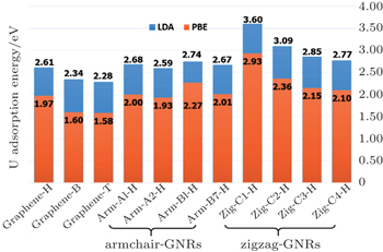
Furthermore, we investigate whether the energy barrier is sensitive to the choice of the functional. The adsorption energies of the U atom on the armchair and zigzag nanoribbons, from the LDA and PBE calculations are shown in Fig.
In comparison to the most stable hollow sites in the systems shown in Fig.
In order to analyse the characteristics of U atoms diffusing on the surfaces of graphene and GNRs, we calculate the energy differences of the stable states and the saddle points along several typical diffusion paths. With the U atom shifting from the centre to the edge of GNRs, the interaction between atom and nanoribbons surface displays the strong edge effect of zigzag-GNRs. For the edge effect, the adsorbate atom has the same probability of migration to both edges. It shows different appearances only if the GNRs have two different edge shapes. Thus, both the width and length of GNR will only influence the number and values of energy barriers, but not the tendency of the edge effect.
It should be noted that we calculate the adsorption energies of different sites by using the rigid model approach. Thus, all the energies of U atom diffusion paths could be obtained at the same level of calculations. The diffusion tendency is elucidated more efficiently by varying the U atom distance to the carbon nanostructure surface until the most stable position is found. Even the stronger adsorption effects at the nanoribbons edges do not deform the carbon hexagonal structure. In a previous study of the characteristic of Li diffusion on graphene, the adsorption energies of Li were tested by using the rigid model approach and fully relaxed approach with LDA and PBE functional.[33] The results with two models achieve the equilibrium distance.
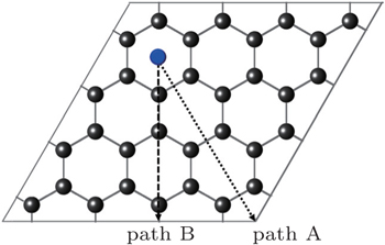
First, we study the diffusion behavior of the U atom on the 2D graphene surface, which is compared afterwards with its behavior on the 1D GNR surface. Owing to the symmetry of the honeycomb lattice, there are two different mechanisms for adatom diffusion on a graphene surface. As shown in Fig.
 | Fig. 4. Schematic representation of the graphene cell used in the calculations and two diffusion paths of A and B on graphene. |
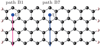
When the monolayer graphene is patterned with gaps or fabricated into ribbons, the symmetry of the honeycomb lattice is broken. GNRs are typical structures like quasi-one-dimensional slices of graphene. The hexagons from the centre of the nanoribbons toward the edge are not equivalent any more. Thus, the properties are sensitive to the edge configurations of GNRs. We first calculate the adsorption energies of U diffusion along different paths in armchair-GNRs. As shown in Figs.
 | Fig. 6. Energy barriers for uranium atom diffusion path A on graphene, path A1 and path A2 on armchair-GNR. |
 | Fig. 8. Energy barriers for uranium atom diffusion path B on graphene, path B1 and path B7 on armchair-GNR. |
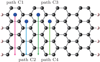
In the case of zigzag-GNRs, it is remarkable that the edge effects are more pronounced than those in the armchair-GNRs. Like the armchair-GNRs case, diffusion paths in C type are first considered, which are parallel to the edge of nanoribbons as shown in Figs.
 | Fig. 9. Schematic representation of the zigzag-GNR cell and four diffusion paths of C1, C2, C3, and C4. |
 | Fig. 10. Energy barriers for uranium atom diffusion path A on graphene, paths C1, C2, C3, and C4 on zigzag-GNR. |
Compared with the cases in armchair-GNRs, it is easier for the U adatom to diffuse and accumulate at the edge in zigzag-GNRs. For other diffusion paths D and E as shown in Fig.
In this work, we study the adsorption behaviours of the main nuclide U on a pristine graphene surface. Using the first-principles density-functional theory, we investigate the stable adsorption sites, the adsorption heights and distortions for U and the graphene system. The most stable position for the U adatom is at the hollow site of a hexagon of bonds, with adsorption energies of −2.61 eV for LDA and −1.97 eV for PBE respectively. However, the U adatom on the top site and bridge site causes much larger distortion of the graphene surface.
Under high temperature and high irradiation circumstances, the graphite materials will exhibit both pristine and defective structures. When the symmetry of the honeycomb lattice is broken, it is necessary to investigate the behaviours of nuclides on the monolayer graphene, whose edge configurations will strongly affect their properties. We identify several distinctive diffusion pathways of graphene surface, armchair-GNRs and zigzag-GNRs. Based on the energy barriers of U atom diffusion characteristics, the edge effects are more pronounced in zigzag-GNRs than in the armchair-GNRs. Thus, U adatoms tend to stay and accumulate at the zigzag edge in the graphene surface. These results illustrate the importance of controlling the initial morphology of nuclear graphite materials for sustainable nuclear fuel materials.
| 1 | |
| 2 | |
| 3 | |
| 4 | |
| 5 | |
| 6 | |
| 7 | |
| 8 | |
| 9 | |
| 10 | |
| 11 | |
| 12 | |
| 13 | |
| 14 | |
| 15 | |
| 16 | |
| 17 | |
| 18 | |
| 19 | |
| 20 | |
| 21 | |
| 22 | |
| 23 | |
| 24 | |
| 25 | |
| 26 | |
| 27 | |
| 28 | |
| 29 | |
| 30 | |
| 31 | |
| 32 | |
| 33 | |
| 34 | |
| 35 | |
| 36 | |
| 37 | |
| 38 | |
| 39 | |
| 40 | |
| 41 | |
| 42 | |
| 43 | |
| 44 | |
| 45 | |
| 46 | |
| 47 | |
| 48 | |
| 49 | |
| 50 | |
| 51 | |
| 52 | |
| 53 | |
| 54 | |
| 55 | |
| 56 | |
| 57 | |
| 58 | |
| 59 | |
| 60 | |
| 61 | |
| 62 | |
| 63 | |
| 64 | |
| 65 | |
| 66 |


