† Corresponding author. E-mail:
‡ Corresponding author. E-mail:
Project supported by the National Magnetic Confinement Fusion Science Program, China (Grant No. 2015GB101001) and the National Natural Science Foundation of China (Grant Nos. 11375236 and 11375235).
A variational principle code which can calculate self-consistently currents on the conductors is used to assess the coupling characteristic of the EAST 4-strap ion cyclotron range of frequency (ICRF) antenna. Taking into account two layers of antenna conductors without lateral frame but with slab geometry, the antenna impedances as a function of frequency and the structure of RF field excited inside the plasma in various phasing cases are discussed in this paper.
Heating in the ion cyclotron range of frequencies (ICRF) is one of the important auxiliary heating methods in the EAST tokamaks. A key issue is the improvement of the coupling between the ICRF antenna and the plasma. Over the past years, a lot of efforts have been made to analyze and design the ICRF antenna.[1–4] In this paper, we will apply a variational theory to evaluate the coupling characteristic of the EAST 4-strap ICRF antenna.
Theihaber and Jacquinot came up with the variational theory to calculate the self-consistent current distribution in the straps of the simple back-to-back ICRF antenna[5] and then improved the coupling code to take into account a more complicated trombone antenna geometry surrounded by an opaque frame[6] in JET. The coupling code was extended by Saigusa et al. so that it can be applied to a toroidal trombone antenna array with solid septa[7] despite its complication. Zhang et al. made some progress on Theihaber and Jacquinot’s coupling code to analyze the ICRF antenna array in HT-7U.[8] In the present paper, the EAST 4-Strap ICRF antenna impedances as a function of frequency and the structure of RF field excited inside the plasma in various phasing cases are presented by using a modification coupling code with the variational theory. For simplicity, the naked ICRF antenna model without lateral structure is employed in spite of the effect produced by the limiter frame while multiple current conductors are taken into account. The rest of this paper is organized as follows. In Section 2 the 4-strap ICRF antenna model is described, and the derivation of the wave equations in vacuum is also re-presented. In Section 3, we investigate the variation of the input impedance at the feeder point relating to antenna parameters and compare the RF field structures in different antenna phasing cases. Conclusions about the 4-strap ICRF antenna model are drawn in Section 4.
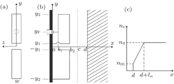
The model of a single antenna is shown in Fig.
 | Fig. 1. Geometry of the coupling model: (a) schematic view, (b) poloidal cross-sectional view for the single ICRF antenna, and (c) plasma density profile. |
| Table 1. Antenna parameters. . |
The back wall of the antenna is located at x = 0, the electrostatic screen at x = c and the plasma edge at x = d. The antenna consists of two main radiating conductors at x = b2 and two return conductors at x = b1. The feeder point connects to the return conductors at y = yF. The upper main radiating conductor short point is placed at y = y1 and the lower main radiating conductor short point is placed at y = −y2. The widths of the conductors in the z direction are both w.
The plasma is assumed to have a linear density profile over a length ln from a low edge density of n01 at x = d to a maximum density of n0 at x = d + ln. The radiation condition is imposed at x = d + ln so that all outgoing waves inside the plasma are absorbed without reflection.
We normalize Maxwell’s equations in the calculations as done in Ref. [5]. The subscript ‘p’ denotes the physical quantity, then:


The current distributions on conductors of the antenna are modeled by


The condition δZA = 0 will lead to the physical current
For simplicity, we assume that the current on the conductor in the z direction is uniform because the conductors are much longer than width, and the width is much shorter than a wavelength at the operating frequency. Then

In order to satisfy continuity conditions at the connections and the short-circuit condition dJy2(y)/dy = 0 at y = y1 and y = −y2, we take advantage of the current distributions corresponding to the transmission line model in the upper and lower conductors, respectively. The upper and the lower antenna loop are balanced (yF = (−y1 + y2)/2), so we can write down the trial functions as follows:


The situation with four identical current straps in the z direction can be treated by rewriting the current distribution and resolving Maxwell’s equations. The current distribution for the N-strap antenna array can be written as


In this section, first we give the frequency scans in the presence of the plasma for a single ICRF antenna. Then, we investigate the antenna behavior dependent on the antenna parameters at 30 MHz around which the EAST ICRF antenna operates frequently. Finally, the field structures corresponding to the single ICRF antenna and the ICRF antenna array are provided.
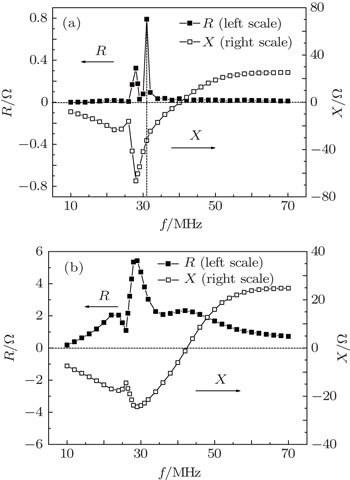
Frequency scans with and without the plasma for a single strap ICRF antenna are shown in Fig.
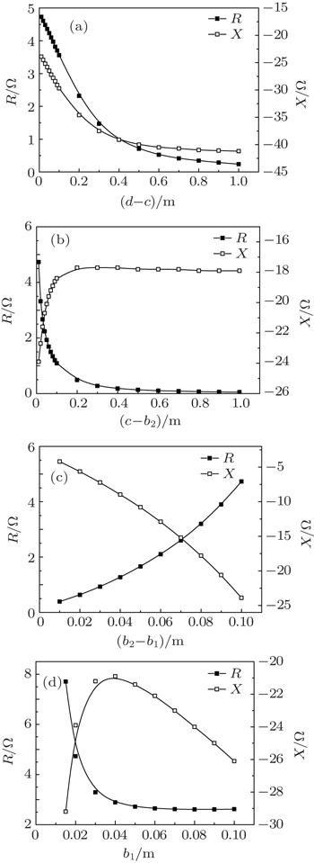
Figure
The three-dimensional (3D) distributions of the electric field |Ey| in the poloidal and toroidal direction at the plasma edge are shown in Fig.
A general variational formalism is used to evaluate the coupling of the ICRF antenna. The antenna resonant frequency is around 30 MHz in vacuum, and the presence of the plasma smooths the peak of the frequency response of the antenna resistance. The antenna resistance in the case of the plasma is much larger than the resistance with the vacuum condition due to the fact that the ICRF waves are absorbed in the plasma. The relationship between the impedance and the antenna parameters can be used to optimize the design of the ICRF antenna by maximizing the resistance R and minimizing the reactance X. The RF electric field distribution of the EAST 4-strap ICRF antenna shows that the antenna array with (0,π,0,π) phasing has lower electric field than with the (0,0,0,0) phasing. The mutual coupling between adjacent straps will be considered in the variational method in the future.
| 1 | |
| 2 | |
| 3 | |
| 4 | |
| 5 | |
| 6 | |
| 7 | |
| 8 |


