Utra-thin anisotropic transmitting metasurface for polarization beam splitter application
Guo Wen-Long, Wang Guang-Ming†, , Ding Shan-Shan, Li Hai-Peng, Cai Tong
Air and Missile Defense College, Air Force Engineering University, Xi’an 710051, China


† Corresponding author. E-mail: wgming01@sina.com

Project supported by the National Natural Science Foundation of China (Grant No. 61372034).

Abstract
Abstract

We report a polarization beam splitter based on phase gradient metasurface for microwave frequency region. The metasurface is constructed by anisotropic cells with independent phase response for differently-polarized waves. Through putting different gradient phases for orthogonally-polarized waves on a focusing metasurface, the anisotropic sample has the ability to enhance gain and split orthogonally-polarized waves. The simulation results indicate that the incident spherical waves are converted into plane waves and split into an x-polarized wave with a refraction angle of −24° and a y-polarized wave with a refraction angle of 37.6° in the y direction. For verification, a metasurface sample with a size of 102.5 mm ×102.5 mm is fabricated and measured. The consistence between numerical and experimental results validates the improved gain of 10.5-dB against the feed source and the splitting effect. Moreover, the thickness of the proposed metasurface is 3 mm which is ultra-thin against the wavelength at 15 GHz. The proposed prescription opens a new route to the applications of anisotropic metasurface in microwave band.

1. Introduction

Metamaterials (MTMs) have a strong ability to manipulate electromagnetic (EM) waves on a subwavelength scale, resulting in fascinating effects such as negative refraction, superimaging/hyperimaging, and anomalous reflection/refraction.[1] A special class of MTM, namely, two-dimensional (2D) metamaterial, also called metasurface, has drawn tremendous attention recently due to extraordinary flexibility to tailor the EM wave and the ease of on-chip fabrication due to its planar profile.[25] Meanwhile, research on metasurfaces explosively expanded from optics to microwave[68] in recent years, especially on gradient metasurface (GM)[911] and planar focusing metasurface (PFM).[1215] For example, by employing V-shaped antennas in a metasurface, the GM and the general reflection/refraction laws were first proposed by Yu et al. in Ref. [1]. Then the PFM was demonstrated and analyzed by adopting I-shaped antennas in Ref. [2]. By employing GM, the mutual high-efficiency conversion between surface-plasmon-like mode and spatial radiated mode was demonstrated in Refs. [3] and [16]. More recently an anisotropic gradient metasurface was perfectly shown in Ref. [17]. Even so, compared with the research on isotropic metasurface, little work on anisotropic metasurface has been published, which still restricts the controlling of the differently-polarized waves.[18,19]

Among the research on anisotropic metasurface, an essential research topic is to manipulate orthogonally-polarized waves independently. For instance, by using a Huygens metasurface the independent controls of orthogonally-polarized transmitted waves are realized in Ref. [20]. By employing anisotropic phase element, the transparent polarization beam splitter is also achieved in Ref. [21]. But note that references [20] and [21] both focused on the polarization beam splitters irradiated by plane waves. Therefore a new way to realize the beam splitter irradiated by spherical waves is still greatly desired. In this paper we first propose an anisotropic refraction metasurface cell, which can manipulate the x/y-polarized refraction waves independently. Then an anisotropic transmitting metasurface is designed and fabricated. Three cases are discussed according to differently-polarized incident waves. The results demonstrate that the spherical waves emitted from the patch antenna have been converted into plane waves and refracted to different directions according to different polarization states.

2. Design of an anisotropic metasurface cell

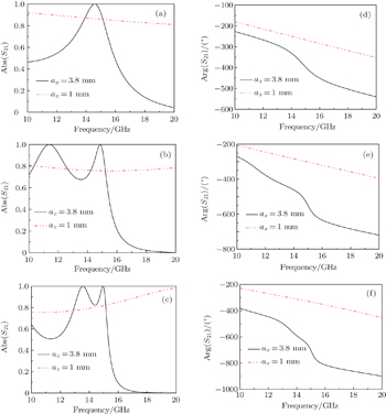
The structure of the metasurface cell is depicted in Fig. 1, in which the rectangular metallic patch structure is employed to control the transmission phases of x/y-polarized EM waves. The dimensions of the structure shown in Fig. 1 are p = 4.1 mm, ax = 3.8 mm, and ay = 3 mm. Meanwhile, the thickness of the dielectric spacer is h = 1 mm while the thickness of the metallic patch structure is h1 = 0.036 mm. The dielectric layer is FR4 with the dielectric constant ɛr = 4.3 and loss tangent 0.01. The frequency-dependent transmission efficiencies and transmission phases of single, double and triple layered element are investigated and the results are shown in Fig. 2. Unanimously, by employing multi-resonance the three dielectric layers and four metallic patch layers are adopted to improve the phase range at a high transmission efficiency level. In order to illustrate the situation that phases of x/y-polarized EM waves are controlled by ax and ay respectively, we fix ay = 3 mm and vary ax from 1 mm to 3.8 mm. Figures 3(a) and 3(b) demonstrate the transmission phases and transmission efficiencies at 15 GHz for x/y-polarized incident waves. It is shown that both the transmission phase and transmission efficiency of the y-polarized wave are almost constant, while the transmission phase of the x-polarized wave varies from −332° to −706° and the transmission efficiency of the x-polarized wave exhibits an oscillatory behavior in a range from 0.75 to 1. Similarly, if ax is fixed at 3 mm and ay is varied from 1 mm to 3.8 mm, the same conclusion can be drawn.
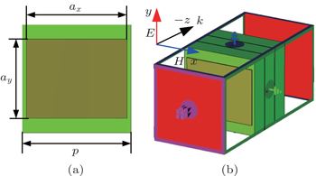
Fig. 1. (a) Top view of the metasurface cell, (b) the perspective view and the simulated setup of the metasurface cell.
Fig. 2. (a)–(c) Frequency-dependent transmitted efficiencies and (d)–(f) frequency-dependent transmission phases of single, double, and triple layered element irradiated by x-polarized wave with ay fixed at 3 mm and ax varying from 1 mm to 3.8 mm.
Fig. 3. (a) Transmission efficiencies and (b) transmission phases at 15 GHz for x/y-polarized incoming waves with ay fixed at 3 mm and ax varying from 1 mm to 3.8 mm.
3. Anisotropic transmission metasurface design and illustrative results

The anisotropic transmitting metasurface is designed based on a focusing metasurface. Here we set the focal length to be 30 mm and first demonstrate the designing principle prior to simulations and experiments. According to the general refraction law as given below

the plane wave impinging on the GM perpendicularly will be refracted to a certain angle with respect to the y direction, which is also called anomalous refraction.

Moreover, considering the fact that the spherical waves can be converted into plane waves by PFM effectively, we can put an extra gradient phase on the PFM lens to obtain the plane waves converted by spherical waves refracted to an anomalous angle. Furthermore, if we put different gradient phases for x/y-polarized waves on the PFM lens, the spherical waves will be split into x/y-polarized plane waves with different refraction angles. According to this point, the phase distributions for x/y-polarized incident waves should meet the phase relationship as described as follows:

where ξ1 and ξ2 represent the phase gradients and, ξx, ξy are the relative phase distributions for x/y-polarized waves respectively. Note that both phase gradients are in the y direction, we will obtain the transmitted beams of x/y-polarized waves refracted in the y direction but with different refraction angles. Meanwhile, the refraction angles of x/y-polarized waves can be calculated by the general refraction law, and they are

According to the above designed principle, we propose a PFM with independently controlling the differently-polarized waves as shown in Fig. 4. The PFM sample and the relative phase distributions of x/y-polarized incident waves are shown in Figs. 4(a)4(c). Moreover, we set the focal length to be 30 mm for x/y-polarized waves and keep ξ1 = π/6p and ξ2 = − π/4p. According to formulas (4) and (5), the x/y-polarized plane waves converted from spherical waves will be refracted to ξtx = −24° and ξty = 37.6° in the y direction. Since the anisotropic metasurface has different responses for different polarization states of the feed source, the cases of x-, y-, and x/y-polarized incident waves are considered below.

Fig. 4. (a) Top view of the proposed PFM, (b) the relative phases of x-polarized waves distributed on the PFM, and (c) the relative phases of y-polarized waves distributed on the PFM.
3.1. Under the irradiation of x-polarized waves

We first simulate a patch antenna with good performance at 15 GHz, which is adopted to act as a feed source. Figures 5(a) and 5(b) show the detailed parameters and return loss of the patch antenna. Meanwhile figure 6 shows the far field pattern of the patch antenna, which shows low directivity. Then the patch antenna is set for the feed source of the PFM, which is polarized along the +x axis. In the course of design, a finite-difference time-domain (FDTD) method based on commercial software CST Microwave Studio 2011 is used to simulate the model of the metasurface sample we have designed. Open boundary conditions are set in all directions, and the three-dimensional (3D) far-field pattern of the anisotropic metasurface is calculated as shown in Fig. 7. In order to illustrate the detailed working procedure, the near-field data in the yoz and xoz planes are shown in Figs. 8(a) and 8(b), respectively. The conclusion can be drawn that the spherical incident wave is converted into plane wave with a refraction angle of −24.6° in the y direction, which is in good accordance with the theoretical results.
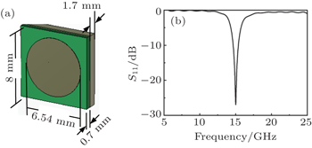
Fig. 5. (a) Patch antenna acting as the feed source of the PFM and (b) the return loss of the patch antenna.
Fig. 6. Far-field pattern of the patch antenna.
Fig. 7. Far-field pattern of the anisotripic metasurface system under the irradiation of x-polarized waves.
Fig. 8. Near-field data of the anisotropic metasurface system in (a) yoz and (b) xoz planes under the irradiation of x-polarized waves.
3.2. Under the irradiation of y-polarized waves

Similarly, we set the polarized direction of the patch antenna to be along the +y axis. With the same simulated setup, the 3D far-field pattern of the anisotropic metasurface is calculated in CST 2011, and the results are shown in Fig. 9. Figures 10(a) and 10(b) show the near-field data in the xoz and yoz planes. Both far- and near-field simulated results demonstrate that the spherical incident wave is not only converted into plane waves but also refracted at an angle of 37° in the y direction, which is in good accordance with the theoretic results.
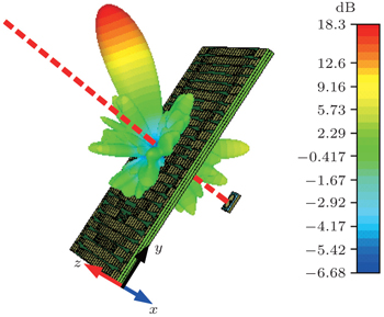
Fig. 9. Far-field pattern of the anisotropic metasurface system under the irradiation of y-polarized waves.
Fig. 10. Near-field data in (a) the yoz and the (b) xoz planes with y-polarized incident waves.
3.3. Under the irradiation of x/y-polarized incident waves

In order to obtain both x/y-polarized incident waves at the same time, the patch antenna is set to be oblique in xoy plane as shown in Fig. 11(b), thereby the polarization state of incident wave can be described as

Here we set φ = 45°, which will keep the amplitudes of x/y-polarized incident waves equal. Then we obtain the sample shown in Fig. 11(a), which is simulated in CST Microwave Studio 2011 where open boundary conditions are set in all directions.

Fig. 11. Anisotropic metasurface system and its feed source. (a) the anisotropic metasurface constructed by the PFM and a patch antenna, and (b) the relative position of the patch antenna in the xoy plane.

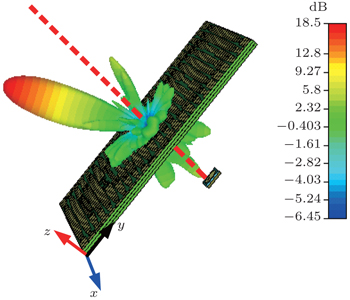
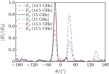
Figure 12 shows the 3D far-field pattern of the anisotropic metasurface in which the great improvements of realized gain against the patch antenna and beam splitting are both obtained. In order to obtain the exact angles that the refracted beams point to, the relative amplitude of E-field in yoz plane is calculated and demonstrated in Fig. 13 where the refraction angles of −24.1° for x-polarized waves and 37.4° for y-polarized waves are obtained at 15 GHz. Moreover the relative amplitude of E-field decreases with frequency offset from 15 GHz. Obviously, the simulation refraction angles are in good accordance with the theoretical ones calculated by the general refraction law. Besides, there is a slight difference in realized gain between the splitting beams, which is due to different effective apertures.

Fig. 12. 3D far-field pattern of the anisotropic metasurface system under the irradiation of x/y-polarized incident waves.
Fig. 13. Relative amplitudes of E-field for x/y-polarized waves at different frequencies in the yoz plane.
3.4. Experimental results under irradiation of x/y-polarized incident waves

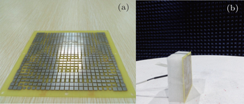
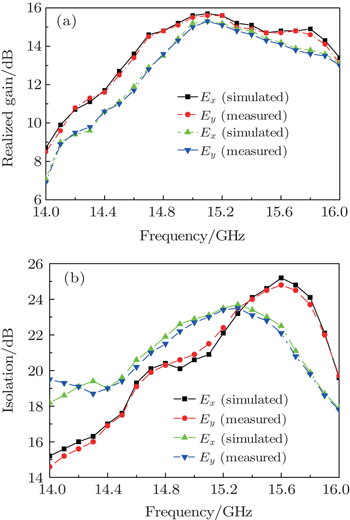
In order to further verify the designing principle, we fabricate a PFM sample with a size of 102.5 mm×102.5 mm by using conventional printed circuit board (PCB) technique. Concrete parameters are consistent with the PFM we have simulated above as shown in Fig. 4(a). The photograph of the sample is shown in Fig. 14 and the measurement is carried out on the antenna test system in a microwave anechoic chamber to reduce the influence of noises. As shown in Fig. 15, the measured results are in good accordance with the simulated ones, indicating that the incident wave from the feed source is split into x-polarized wave with a refraction angle of −24° and y-polarized wave with a refraction angle of 37.6° in the y direction. Moreover, due to different effective apertures, the realized gain of x-polarized refracted wave is 15.6 dB which is 0.4 dB bigger than that of the y-polarized refracted wave. Besides, to analyze the operating bandwidth, double factors will be taken into consideration. One factor is the 1-dB gain bandwidth. We show the 1-dB gain bandwidth for x- and y-polarized waves in Fig. 16(a), from which the x-polarized waves operate from 14.6 GHz to 15.5 GHz while the y-polarized ones work in a frequency range of 14.7 GHz–15.6 GHz. That is to say, the 1-dB gain bandwidth of the splitter ranges from 14.7 GHz to 15.5 GHz. The other factor we consider here is the polarization isolation. As shown in Fig. 16(b) the polarization isolation degrees for x- and y-polarized waves are plotted. With the isolation level above 20 dB, we will obtain that the x-polarized waves operate from 14.7 GHz to 15.9 GHz while the y-polarized ones work in at 14.6 GHz–15.6 GHz. In other words, the bandwidth of isolation level above 20 dB is from 14.7 GHz to 15.6 GHz. In summary, the bandwidth with gain reducing 1 dB and polarization isolation level above 20 dB is from 14.7 GHz to 15.5 GHz.

Fig. 14. (a) Top view and (b) the test view of the fabricated sample.
Fig. 15. Simulated and measured far-field radiation patterns at 15 GHz of the anisotropic metasurface system with x/y-polarized incident waves.
Fig. 16. Simulated and measured (a) realized gain and (b) polarization isolation degree for x- and y-polarized waves.
4. Conclusions and perspectives

In this work, we demonstrate an utra-thin beam splitter through using anisotropic metasurface. By putting different gradient phases of x/y-polarized waves on a PFM, we also show a new designing principle of anisotropic metasurface. Both simulated and measured results demonstrate great improvements of the patch antenna gain and perfect beam splitting effect, which possesses great application values in the anisotropic devices, high gain antennas, lens, etc.

Reference
1Yu N FPatrice GMikhail A KFrancesco AJean-Philippe TFederico CZeno G 2011 Science 334 333
2Li XXiao S YCai B GHe QCui T JZhou L 2012 Opt. Lett. 37 4940
3Qu CMa S JHao J MQiu MLi XXiao S YMiao Z QDai NHe QSun S LZhou L 2015 Phys. Rev. Lett. 115 235503
4Holloway C LKuester E FGordon J AO’Hara JBooth JSmith D R2012IEEE Antenn. Propag. M.5410
5Pu M BChen PWang C TWang Y QZhao Z YHu C GHuang CLuo X G 2013 AIP Adv. 3 052136
6Yang Q LGu J QWang D YZhang X QTian ZOuyang C MRanjan SHan J GZhang W L 2014 Opt. Express 22 25931
7Qu S WWu W WChen B JYi HBai XNg K BChan C H 2015 Sci. Rep. 5 9367
8Li Y FZhang J QQu S BWang J FZheng LZhou HXu ZZhang A X 2015 Chin. Phys. 24 014202
9Zhang KDing X MZhang LWu Q 2014 New J. Phys. 16 103020
10Li Y FZhang J QQu S BWang J FWu XXu ZZhang A X 2015 Acta Phys. Sin. 64 094101 (in Chinese)
11Sun S LYang K YWang C MJuan T KChen T KLiao C YHe QXiao S YKung W TGuo G YZhou LTsai D P 2012 Nano Lett. 12 6223
12Chiya Svan der Daniel W 2015 Appl. Phys. Lett. 106 113110
13Anders PMichael G NRene L ESergey I B 2013 Nano Lett. 13 829
14Kang MFeng T HWang H TLi J S 2012 Opt. Express 20 15882
15Sun Y YHan L SXiao YWang Z NLiu D H 2013 Acta Phys. Sin. 62 104201 (in Chinese)
16Xu J JZhang H CZhang QCui T J 2015 Appl. Phys. Lett. 106 021102
17Ma H FWang G ZKong G SCui T J 2015 Sci. Rep. 5 9605
18Zheng JYe Z CSun N LZhang RSheng Z MZhang J 2014 Sci. Rep. 4 6491
19Wang Y QPu M BHu C GZhao Z YWang C TLuo X G2013Opt. Commun.31914
20Jia S LWan XBao DZhao Y JCui T J 2015 Laser Photon. Rev. 9 545
21Cai TWang G MZhang X FLiang J GZhuang Y QLiu DXu H X 2015 IEEE Trans. Antenn. Propag. 63 5629