Optimization of loss and gain multilayers for reducing the scattering of a perfect conducting cylinder
Yu Zhen-Zhong†, , Zhao Guo-Shu, Sun Gang, Si Hai-Fei, Yang Zhong
School of Intelligence Science and Control Engineering, Jinling Institute of Technology, Nanjing 211169, China


† Corresponding author. E-mail: nanfish@jit.edu.cn

Project supported by the Research Foundation of Jinling Institute of Technology, China (Grant No. JIT-B-201426), the Jiangsu Modern Education and Technology Key Project, China (Grant No. 2014-R-31984), the Jiangsu 333 Project Funded Research Project, China (Grant No. BRA2010004), and the University Science Research Project of Jiangsu Province, China (Grant No. 15KJB520010).

Abstract
Abstract

Reduction of electromagnetic scattering from a conducting cylinder could be achieved by covering it with optimized multilayers of normal dielectric and plasmonic material. The plasmonic material with intrinsic losses could degrade the cloaking effect. Using a genetic algorithm, we present the optimized design of loss and gain multilayers for reduction of the scattering from a perfect conducting cylinder. This multilayered structure is theoretically and numerically analyzed when the plasmonic material with low loss and high loss respectively is considered. We demonstrate by full-wave simulation that the optimized nonmagnetic gain-loss design can greatly compensate the decreased cloaking effect caused by loss material, which facilitates the realization of practical electromagnetic cloaking, especially in the optical range.

1. Introduction

In 2006, transformation optics (TO), first proposed by Pendry et al., was introduced as a technique to manipulate the electromagnetic (EM) wave propagation.[1] TO can be used to design different kinds of novel EM devices, and the most significant device designed by TO is the invisibility cloak which can conceal an object from detection by EM illumination.[2,3] Apart from various theories on the cloak that have been analyzed extensively, some experimental verifications have also been reported from microwave to optical frequencies with assistance of artificial EM materials.[4,5] As the magnetic responses of natural materials, even artificial EM materials, are weak in the optical regime, a reduced set of medium parameters has been proposed to solve the problem of optical cloaking, which is still difficult to fabricate practically.[5]

Another approach to cloaking is to use layers of isotropic plasmonic shells or metamaterials to cover the cloaked object.[68] This approach based on scattering cancellation mechanism can drastically reduce the total scattering cross section of an object, which is only limited to the dimension of the object much smaller than the EM wavelength. Moreover, the optimization procedure used to design layers of non-magnetic moderate-size cloaking shells can achieve satisfactory cloaking performance.[9,10] However, these optimized shells with layers of anisotropic metamaterials for hiding a perfect electric conductor (PEC) cylinder are difficult to fabricate in practice. Afterwards, Yu proposed optimized cylindrical multilayers composed of isotropic dielectric and plasmonic material.[11] Besides, another optimized design made of normal dielectrics was proposed, which further simplifies the fabrication but induces a noticeable scattering when the radius of the cloaked target is compared with the working wavelength.[12]

To achieve good cloaking performance, we continue the optimized studies on designing non-magnetic multi-layers made of gain and loss materials through a genetic algorithm (GA). In our previous work, lossless plasmonic materials have been used with permittivities far less than unity which are always accompanied with losses.[11] As reported in Han’s paper, the gain-assisted method can be used to overcome the loss problem of the invisibility cloak.[13] Therefore, considering introduction gain in the dielectric material to compensate the loss in the plasmonic material, we demonstrate that the optimized gain-loss shells can yield much better performance than cloaking shells designed with only lossy materials.

2. EM scattering analysis of a cylindrical multilayered structure

For simplicity, we consider a two-dimensional cylindrical multilayer constructed alternately by two kinds of non-magnetic materials: one is a lossy plasmonic material, the other is a dielectric gain material. Let us assume that a TM uniform plane wave is traveling in the +x direction upon the multi-layer cylindrical structure with inner radius a and outer radius b, as depicted in Fig. 1.
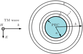
Fig. 1. TM plane wave incident on a PEC cylinder surrounded by multi-layers of alternating material A and material B. The inner and outer radii of the coating are a and b, respectively.

The form of time-harmonic variation is represented by ejωt throughout this paper. The normalized magnetic field polarized along the cylinder axis can be written as , where . As the multi-layer cylindrical structure is considered, it is desirable that the plane wave should be represented by the sum of cylindrical wave functions in the cylindrical coordinates (r,ϕ,z)[14]

where Jn is the Bessel function of the first kind.

The scattered magnetic field from the multilayers can be represented by the sum of Hankel functions of the second kind as

The magnetic field in layer m (m = 1, 2, …, M) of the multilayered structure can be described as

where km represents the wave number in layer m. An, Bmn, and Cmn represent the yet unknown coefficients which can be determined by applying the boundary condition of each layer. The EM scattering by a two-dimensional (2D) target is usually represented by the scattering width (SW)[14]

From Eq. (4), the SW of the multilayers varies as a function of angle ϕ. To achieve the invisibility, we should maximally reduce SW in all directions using global optimization of the genetic algorithm (GA). Therefore, we choose the sum of SW from 0° to 180° as the fitness function that has been discussed in the previous paper. Moreover, this optimization method could be extended to different goals of scattering, for example super-scattering, by choosing different fitness functions.

3. Optimized multilayers made of gain and loss materials

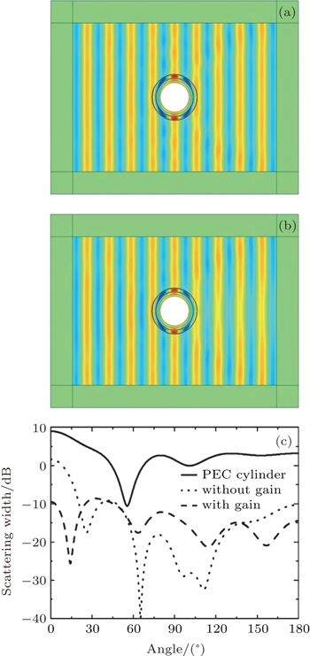
To simplify the multilayered structure, we consider a five-layer structure composed of two layers of dielectric gain material A sandwiched by three layers of lossy plasmonic material B. The complex permittivities of the gain and loss materials can be expressed as and , respectively. To begin with, the electric loss tangent tan with a relatively low value 0.1 is considered. The radius of inner PEC core is fixed to be 2λ/3, and the thickness of each shell is changeable with total five-layer thickness less than 2λ, where λ is the wavelength of the incident EM wave. When applying GA, the fitness function is defined as , where ti (i = 1, …, 5) is the thickness of each layer. The GA searches the optimal parameters by approximating fitness function to lowest value, namely, minimizing the scattering by the five-layer structure. Table 1 lists the optimized parameters with the gain material ɛA = 6.847 + i0.275 and the loss plasmonic material ɛB = 0.0804(1 − 0.1i). We demonstrate by full-wave EM simulation that the performance of the optimized multilayers constructed by gain and loss materials is better than that in the case of using only loss materials, as shown in Figs. 2(a) and 2(b). We can see that the scattering of the optimized multilayers is significantly reduced in the two cases in Figs. 2(a) and 2(b) and only slight shadow in the forward direction of the no-gain structure. The far-field SW normalized to the working wavelength has also been calculated and compared in Fig. 2(c). The SW for the optimized multilayered cover with gain is below −10 dB at most of the angles and for the no-gain cover also exhibits low level except at the forward direction (about 2 dB).

Table 1.

The permittivity and thickness for the optimized low-loss five-layer structure with gain material.

.

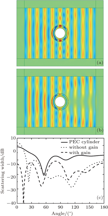
As to the second example, we study the case of high loss with loss tangent 0.5. Through optimization, the complex permittivities of the gain material and the loss plasmonic material are calculated with resulting values ɛA = 5.158 + i1.131 and ɛB = 0.0355(1 − 0.5i), respectively. The field profiles and the far-field SW for the multilayered cover using the optimized parameters from Table 2 are also shown and compared in Fig. 3. As can be clearly seen from the field distribution of no-gain cover in Fig. 3(b), a shadow in the forward direction is evident with SW of 12 dB at angle ϕ = 0 in Fig. 3(c), caused by the serious losses of plasmonic material. From the above two optimized examples, we conclude that the backward scattering from the optimized layers with gain is changed slightly, but the forward scattering is reduced dramatically.

Fig. 2. The total magnetic field distribution for the optimized low-loss gain-assisted multilayers (a) and for the low-loss multilayers without gain (b). The scattering width (c) normalized by wavelength for the PEC cylinder (solid), for the optimized low-loss multilayers with gain (dashed), and for the multilayers without gain (dotted).
Table 2.

The relative permittivity and thickness for the optimized high-loss five-layer structure with gain material.

.
Fig. 3. The total magnetic field distribution for the optimized high-loss gain-assisted multilayers (a) and for the high-loss multilayers without gain (b). The scattering width (c) normalized by wavelength for the PEC cylinder (solid), for the optimized high-loss multilayers with gain (dashed), and for the multilayers without gain (dotted).

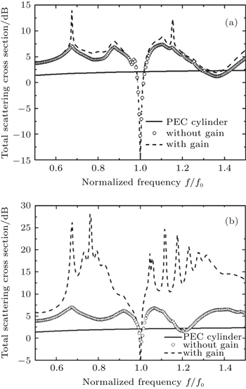
The plasmonic material always disperses heavily as frequency changes. Here, the plasmonic material is supposed to follow the Drude model with , where fp is the plasma frequency and γ represents the material absorption. In the low-loss case, the permittivity of the gain dielectric has been optimized as ɛA = ɛ0 (6.847 + 0.275i), for simplicity, supposed to be a constant in an adjacent frequency domain. In the Drude model, we choose γ = 9.12× 10⁻³fp and the design frequency f0 = 1.04 fp to ensure the low-loss plasmonic material ɛ(f0) = ɛ0 [0.0804(1 + 0.1i)]. In the high-loss case, the optimized gain material is ɛA = ɛ0 (5.158 + 1.131i). We choose γ = 1.87× 10⁻²fp and f0 = 1.018fp. In this way ɛ(f0) = ɛ0 [0.0335(1 + 0.5i)]. Figure 4 shows the frequency dependence of the total scattering cross section normalized by the geometrical cross section of the PEC cylinder, for the uncloaked PEC cylinder (solid line), for the optimized cover with gain (dashed line) and for the no-gain cover (circle dot). It is evident that the optimized cylindrical multilayers allow a drastic reduction of the scattering at the design frequency f0, in Fig. 4(a). The normalized total scattering cross section is reduced by about 17 dB (with gain) and 12 dB (without gain) with respect to the uncloaked scenario. In the high-loss case (Fig. 4(b)), the total scattering cross section is reduced by about 8 dB (with gain) and 3 dB (without gain) at the design frequency.

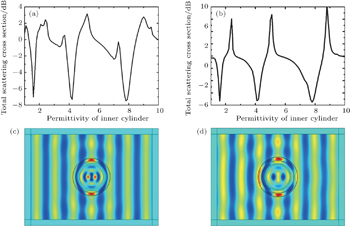
What happens if we exchange the inner PEC cylinder for a dielectric one? We plot the dependency of normalized total scattering cross section on the permittivity of the inner dielectric cylinder. Although the original purpose of the optimized multilayered cover is to conceal the inner PEC cylinder, it is amazing to find that the multilayers are also effective to reduce the scattering of the inner dielectric core with some specific permittivities, shown in Fig. 5(a). We notice that three sharp dips appear at the relative permittivity of 1.6, 4.2, and 7.8, respectively. To demonstrate the above calculated results, full-wave simulations with an inner dielectric ɛ = 7.8 have been carried out to visualize the field distribution, exhibiting acceptable cloaking performance in Fig. 5(c). Moreover, the scattering for the high-loss gain-assisted multilayers is also studied by total scattering cross section (Fig. 5(b)) and full-wave simulation with inner cylinder ɛ = 4.2 (Fig. 5(d)). These full-wave simulations show that EM wave can penetrate into the dielectric core and communicate with the outside world, but does not produce noticeable scattering.[15] It is worth noting that the permittivities of the inner cylinder corresponding to the dips for those two optimized multilayer covers are almost the same, due to the same initial goal of minimizing the scattering from the PEC cylinder of the same size.

Fig. 4. In the low-loss (a) and high-loss (b) cases, the normalized total scattering cross section as a function of normalized frequency for the uncloaked PEC cylinder with radius a = 2λ/3 (solid), for the optimized five-layer low-loss cloak with gain material (dashed), and for the optimized cloak without gain (circle dot).
Fig. 5. The normalized total scattering cross section as a function of permittivity of the inner dielectric cylinder covered by low-loss gain-assisted multilayers (a) and high-loss gain-assisted multilayers (b). The total field distribution for the optimized low-loss gain-assisted multilayers with an inner dielectric ɛ = 7.8 (c) and for the optimized high-loss gain-assisted multilayers with an inner dielectric ɛ = 4.2 (d).

The isotropic plasmonic material with relative permittivity close to zero in this design is available at infrared and visible ranges, for example, the noble metals, polar dielectrics, some semiconductors, and even composite materials realized by embedding metallic nano-particles and nano-wires into dielectrics.[1619] These plasmonic materials, in general, are unavoidably endured with losses at infrared or visible wavelengths, which will affect the cloaking performance of the optimized multilayers. This troublesome problem could be conquered by introducing proper gain in the dielectric material. The gain can be achieved by quantum dots and III–V semiconductors at long wavelengths (about 1500 nm) and by dye at short wavelengths (for example, PMMA with Rhodamine 6G dye at wavelength of 594 nm).[20] Moreover, giant gain coefficients of 6755 cm−1 and 6.8× 104 cm−1 are reported for a CdSe nano-belt and a layer of InAs/GaAs quantum dot, respectively.[21,22] These gain values indicate that the gain materials are expected to achieve the isotropic gain-assisted cloaking device.

4. Conclusion

In conclusion, we have studied the optimization design of alternating layers of isotropic gain and loss materials, which can overcome the loss problem in the invisibility of PEC core. We have demonstrated by full-wave EM simulation that the performance of the optimized isotropic gain-loss cloak is much better than that of the one without adding gain materials, especially in the reduction of the forward EM scattering. Moreover, when in the inner domain we replace the PEC cylinder with a dielectric material of some specific permittivities, the optimized multilayers are also effective to reduce the EM scattering. This optimized design approach by introducing the gain material properly can compensate the plasmonic material’s loss, which can be extended to design other transformation optics devices.

Reference
1Pendry J BSchurig DSmith D R 2006 Science 312 1780
2Kwon D HWerner D H 2008 New J. Phys. 10 115023
3Yu Z ZFeng Y JWang Z BZhao J MJiang T 2013 Chin. Phys. 22 034102
4Schurig DMock J JJustice B JCummer S APendry J BStarr A FSmith D R 2006 Science 314 977
5Cai WChettiar U KKildishev A VShalaev V M 2007 Nat. Photo. 1 224
6Alù AEngheta N 2005 Phys. Rev. 72 016623
7Alù AEngheta N 2007 Opt. Express 15 3318
8Alù AEngheta N 2008 Phys. Rev. Lett. 100 113901
9Popa B ICummer S A 2009 Phys. Rev. 79 023806
10Xi SChen H SZhang BWu B IKong J A 2009 Phys. Rev. 79 155122
11Yu Z ZFeng Y JXu X FZhao J MJiang T 2011 J. Phys. D: Appl. Phys. 44 185102
12Wang XSemouchkina E 2013 Appl. Phys. Lett. 102 113506
13Han T CQiu C WHao J MTang X HZouhdi S 2011 Opt. Express 19 8610
14Balanis C A1989Advanced Engineering ElectromagneticsNew YorkWiley
15Luo X YLiu D YYao L FDong J F2014Acta Phys. Sin.63084101(in Chinese)
16Rivas J GJanke CBolivar PKurz H 2005 Opt. Express 13 847
17Johnson P BChristy R W 1972 Phys. Rev. 6 4370
18Garcia NPonizovskaya E VXiao J Q 2002 Appl. Phys. Lett. 80 1120
19Garcia NPonizowskaya E VZhu HXiao J QPons A 2003 Appl. Phys. Lett. 82 3147
20Dai D XShi Y CHe S LWosinski LThylen L 2011 Opt. Express 19 12925
21Liu NWei HLi JWang Z XTian X RPan A LXu H X 2013 Sci. Rep. 3 1967
22Kirstaedter NSchmidt O GLedentsov N NBimberg DUstinov V MEgorov A YZhukov A EMaximov M VKopev P SAlferov Z I 1996 Appl. Phys. Lett. 69 1226