Electrical control of magnetism in oxides
Song Cheng†,  , Cui Bin, Peng Jingjing, Mao Haijun, Pan Feng
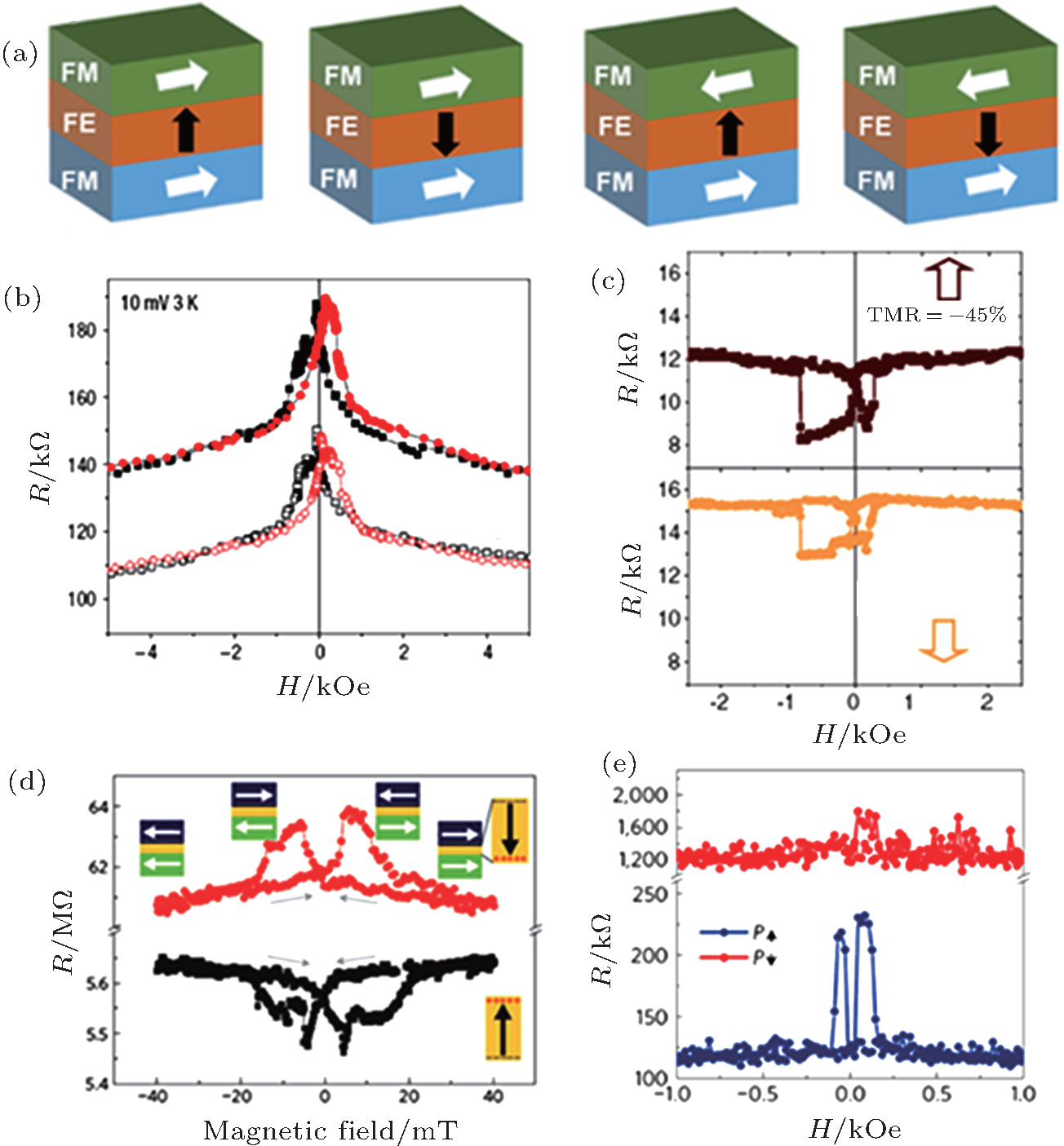
, Cui Bin, Peng Jingjing, Mao Haijun, Pan Feng (a) Schematic diagram of the four resistance states in artificial MFTJS with two FM electrodes sandwiching an FE tunnel barrier. The white and black arrows represent the magnetic configurations and FE polarization, respectively. (b) Tunnel magnetoresistance curves at 4 K with