Control of Hall angle of Skyrmion driven by electric current
Liu Gao-Bin1, 2, †, , Li Da1, P F de Chatel3, Wang Jian1, 2, Liu Wei1, Zhang Zhi-Dong1
Shenyang National Laboratory for Materials Science, Institute of Metal Research, Chinese Academy of Sciences, Shenyang 110016, China
School of Science, University of Science and Technology Liaoning, Anshan 114051, China
MTA-DE Particle Physics Research Group, H-4010 Debrecen P. O. Box 105, Hungary


† Corresponding author. E-mail: gbliu12b@imr.ac.cn

Project supported by the National Natural Science Foundation of China (Grant No. 51331006) and the Fund from the Chinese Academy of Sciences (Grant No. KJZD-EW-M05).

Abstract
Abstract

Skyrmions are very promising for applications in spintronics and magnetic memory. It is desired to manipulate and operate a single skyrmion. Here we report on the thermal effect on the motion of current-driven magnetic Skyrmions in magnetic metal. The results show that the magnon current induced by the thermal gradient acts on Skyrmions via magnonic spin-transfer torque, an effect of the transverse and longitudinal Skyrmions drift velocities, thus leading to the effective manipulation of the Hall angle through the ratio of thermal gradient to electric current density, which can be used as a Skyrmion valve.

PACS: 72.25.–b;73.43.Cd;75.70.Kw;75.40.Gb
1. Introduction

A Skyrmion is a topologically stable spin texture which consists of opposite core spins and peripheral spins swirling up with a unique spin chirality determined by the underlying chiral crystal structure of the hosting material.[1,2] Since they were observed in 2009,[3] magnetic Skyrmion crystals (SkX) have been extensively investigated, and by now they have been discovered in various materials. There are three kinds of materials. (i) The cubic chiral B20-type helimagnets with lattices exhibiting broken or lacking parts. The materials configurations can be crucially stabilized by the strong Dzyaloshinskii–Moriya interaction (DMI) in these materials,[4] such as MnSi,[57] Fe1−xCoxSi,[8,9] FeGe,[1012] β-Mn-type chiral magnet,[13] and Cu2OSeO3.[14,15] (ii) The non-spiral materials where the Skyrmions state can be induced by the competing of exchange interaction with other strong magnetostatic interactions[1618] whether there is DMI or not, i.e. the four-spin interaction, typically the monolayer Fe/Ir (111) where the 3d–5d hybridization between the Fe monolayer and the Ir substrate plays a key role in determining the unusual magnetic properties.[16,17,19] (iii) The artificial material in which an artificial skyrmion is created by embedding a magnetic vortex into an out-of-plane aligned spin environment.[2022] Skyrmions are very promising for applications in spintronics[23,24] due to their topological stabilities, ultimate small sizes and low dissipations, and varieties of methods have been proposed to control the creation, movement and removal of a Skyrmion.[20,25,26] Proposals of manipulations and operations of Skyrmions are highly desired.[27]

A Skyrmion can be manipulated with ultralow energy consumption due to its extremely small threshold current density (∼106 A·m−2) compared with that of a domain wall in ferromagnet (∼ 1011 A·m−2), because the Skyrmion lattices in a chiral magnet are coupled very weakly to the atomic crystal structure and pinned very weakly to disorder, and electric currents couple very efficiently to Skyrmions in addition.[23] When an electric current flows through a ferromagnetic metal, the conduction electron spins are coupled ferromagnetically to, i.e., forced to be parallel to the localized spin at each atomic site by Hund’s-rule coupling, eventually collecting a Berry phase, which arises from an emergent electromagnetic field or fictitious electromagnetic field in real space. At the same time the current becomes spin-polarized, and spin angular momentum is transferred to the magnetization through the mechanism known as spin-transfer torque (STT) due to spin conservation.[28] Consequently the electron current drives the flow of Skyrmions. The motion of the Skyrmions leads to a temporal change of the emergent magnetic field and hence to an emergent electric field due to electromagnetic induction. On the one hand, the induced emergent electric field acts on the electrons like the ordinary magnetic field, and, in particular, gives rise to a Lorentz-type force, which deflects electrons and results in the topological Hall effect.[2932] On the other hand, the velocity of the Skyrmion has its transverse component, that is, the Skyrmion Hall effect arises, albeit with a small constant.[29,33,34] However, Skyrmions can also be manipulated by the magnon current induced by thermal gradient due to the coupling of magnetization to magnonic spin transfer torque even in the absence of charge flows, and move from the cold to the hot region.[35,36] Recently, Troncoso and Núñez have shown that thermal torques can increase the mobility of Skyrmions by several orders of magnitude.[37] The progress in the magnetic skyrmions in chiral magnetic materials has been reviewed in Refs. [38] and [39].

In the present study, we investigate the dynamics of Skyrmions in a thin film of metallic chiral magnet in the presence of a thermal gradient and an electric current. Based on the stochastic Landau–Lifshitz–Gilbert–Slonczewski (LLGS) equation[40] the dynamic equation for Skyrmions is derived. The equation is in the form of a generalized Thiele’s equation that describes the dynamics of a single Skyrmion at finite temperature. The results show that the Hall angle can be manipulated by the spin-transfer torque induced by a magnon current and an electric current. Based on the dependence of the Hall angle on the ratio of the thermal gradient to the electric current density, a Skyrmion valve is proposed.

2. Skyrmiom motion

We consider a thin film of a metallic chiral magnet well below the Curie temperature (Fig. 1), which is described by the magnetic free energy density F(mim) (here i = xy; double indices are summed over)

where m = M/Ms is a unit vector denoting the magnetization direction, M the local magnetization and Ms = |M| a fixed saturation magnetization modulus, Jex the exchange stiffness, Hext the external field, which is perpendicular to the thin film, and Dd the strength of the DMI, which is the lowest-order chiral spin-orbit interaction originating from the relativistic effect that occurs due to the lack of inversion symmetry of the atomic structure. Generally, the strongest energy scale is ferromagnetic, which favors a uniform magnetization configuration. It is followed by the weaker DMI, which favors twisted magnetic structures typically by forming a spiral-like magnetization configuration that varies in size according to the competing DMI and ferromagnetic exchange interaction. The system favors a spiral configuration of magnetic moments (conical state) with a single wave vector due to the competition between the magnetic exchange and the DMI and then gradually becomes a stable Skyrmion lattice with triplet-vector in a range of applied magnetic fields from to ,[4143] eventually is saturated to a ferromagnetic state at a higher field. Skyrmions are observed experimentally to keep stability much more easily in a thin film of helical magnet.[5,10,44] The mechanism to stabilize chiral Skyrmions is considered to originate from the chiral modulation across the thin film radically changing the Skyrmion energetics and providing a thermodynamical stability of a Skyrmion lattice in a wider range of applied magnetic fields.[45] Here we assume that the rigidity of Skyrmions has stability over a broad range of temperatures and magnetic fields in the thin film.

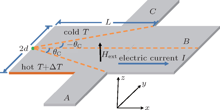
Fig. 1. Schematic of device, where the electric current flows from left to right and the applied magnetic field is perpendicular to the thin film.

The standard Landau–Lifshitz–Gilbert (LLG) equation is phenomenological and widely used to model magnetization dynamics, including the dynamics of the magnetization direction of the skyrmion lattice due to the very smooth magnetic structure in the skyrmion lattice phase and slight changes of its amplitude. Slonczewski has studied the effect of current-driven spin-transfer torque on magnetization.[40] However, when one studies the dynamics of skyrmions in metal magnets it is necessary to introduce another two novel damping terms relevant to non-collinear spin textures, −α′{m·[im × tm]}im originating from Ohmic damping of electrons coupled by Berry phases to the magnetic structure,[24,36] and −β′{m·[im × (υs·)m]}im for the need of Galilean invariance, where vs is an effective spin velocity parallel to the spin current density. These terms might actually be the dominating ones in a good metal[46] except for non-adiabatic spin-transfer torque βm × (υs·)m.[47] So the extended LLGS equation[40] containing hl the random fluctuating of Heff is expressed as

Here, γ = Ms/s is the gyromagnetic ratio, s the saturation spin density, υs = −(pa3/2eMs)j is the spin velocity of the conduction electrons defined as the ratio of the spin current to the size of the local magnetization for smooth magnetic structures with constant amplitude of the magnetization,[46] with p being the spin polarization of the electric current density j, which is over the threshold current density, e (> 0) the elementary charge, and a the lattice constant, while α denotes the Gilbert damping coefficient. The LLGS equation contains the adiabatic spin-transfer torque given by (υs·)m, and the non-adiabatic spin-transfer torque given by β(m × vs·)m, where the strength of the non-adiabatic spin-transfer torque is characterized by the parameter β. The random Langevin field hl, which describes the fluctuating torques, is defined by the uncorrelated Gaussian white noises[48]

which implies a Brownian motion of the Skyrmion. The Brownian motion vanishes on average along the direction perpendicular to the temperature gradient. While the Skyrmion is pushed by the Brownian motion from the hot side towards the cold side, and opposite by the magnon current along the direction parallel to the temperature gradient. However the velocity contributed by the Brownian motion is too small to mention it compared with the contribution of the magnon current.[35,36]

The effective field is derived from the free energy density, Eq. (1), as follows:

Induced by the magnon current, the normalized magnetization m can be decomposed into the slow component ms corresponding to the equilibrium configuration of the Skyrmion, and the fast component mf orthogonal to ms:[36]

Following the procedure in Refs. [49] and [50] and the coarse-graining over mf where linear terms in mf can be discarded by taking the average over time because mf is a fast mode behaving as a function of the sine or cosine form in time,[36] equation (2) becomes

where the tensor J = γJexmf × mf/Ms (Ref. [35]) is the spin current density with polarization along ms carried by magnons[36,49] and the magnon spin transfer torque is given by iJ = Jiims,[49,50] βs is the dissipative correction to the thermomagnonic torque, and Ji is the magnon current density.

3. Application to the dynamics of the Skyrmion

Following the Thiele approach,[51] a modified version of Newton’s equation describing the translational motion of a Skyrmion domain[52] is derived by multiplying both sides of Eq. (6) with ms × (cross product) and then with ms· (dot product), and integrating the resulting equation over the area around the Skyrmion or the Skyrmion domain finally[46] the following equation is obtained:

Here the first term on the left-hand side of the above equation describes the Magnus force. The gyromagnetic coupling vector G = −4πez with ez being the unit vector along the z direction or the direction of the applied field. = tR is the drift velocity of the Skyrmion. The second term represents the friction of the Skyrmion. The components Dij of the tensor D are Dxx = Dyy = D and 0 otherwise. Similarly, the components Dij of the tensor D are Dxx = Dyy = D′ and 0 otherwise. The first and second term on the right-hand side are the forces on Skyrmions arising from electric current (Fc) and magnonic current or temperature gradient (Fm). The third term Fpin is the force acting on the spin texture from the boundaries, impurities, magnetic field, etc. Our attention focuses on the motion driven by the current transverse to the edge. The Skyrmions are affected by a repulsive potential from the boundary only within a range of about a size of a Skyrmion, and cannot reach the boundary because it cannot overcome the repulsive potential if the electric current density is not over 1011 A/cm2.[53] So it is reasonable to neglect the effect of boundary when Skyrmions are far from the boundary. The Fpin can be neglected also when |Gvs| ≫ |Fpin| is satisfied.[54]

4. Control of the Hall angle

For the steady translation motion, the magnetization profile of a rigid Skyrmion domain is represented by ms(r,t) = ms(rR(t)) where R(t) = υdt, υd is the drift velocity of the Skyrmion,[36,37,54] when the electric current is flowing in the x direction while the magnon current is flowing in the y direction as shown in Fig. 1. The present situation can be described by setting vsy = Jy = 0, Fpin = 0, vsx = vs and Jx = J in Eq. (7). The resulting drift velocity components perpendicular and parallel to the flow direction of the electric current read

where η = D/4π is dimensionless, which encodes the information about the strength Dd of the DMI and the applied field Hext is called the form factor (or shape factor) of a Skyrmion.[29] Generally the form factor is close to unity.[36,55]

Inserting the outcome of the previous section into the definition of the Hall angle θH, we have

From Eq. (10), it is evident that tanθH → ∞ or θHπ/2 as , and or θH ≈ −π/2 as J/vs → ∞. In Fig. 2, we show the dependence of the Hall angle on the ratio of magnon current density induced by the thermal gradient to electric current density for typical parameters. So the maximal (minimal) Hall angle approaches π/2 (−π/2). Thus the Hall angle can be controlled in a wide range, which is useful in spintronics.

Fig. 2. Dependence of the Hall angle on J/vs. For estimates we have taken , , βs = 0.032, and η = 1.4.
5. Skyrmion valve

Finally, we propose a Skyrmion valve in confined geometries based on the control of the Hall angle. The setup of the Skyrmion valve is shown in Fig. 1. The Skyrmion can indeed be drained by an additional terminal, like the setup reported by Jiang et al.[56] Then the Skyrmion will be driven by the Magnus force and the dissipative force, and may arrive at any of the edges of the thin film. Subsequently, the repulsive potential of the boundary induces a motion transverse to the boundary because of the Magnus force,[53,54,57] and eventually the Skyrmions would move along the edges from left to right due to the edge effect.

Generally, , so Under these conditions the Hall angle can be reduced into

The Skyrmion would move along the A channel when θC < θH, that is,

where the critical angle θC = tan−1(d/L), and is neglected since is satisfied usually.

Obviously, there is an equilibrium between the transverse force induced by electric current and the longitudinal forces induced by magnon current when

When the equilibrium is reached, the value of βs becomes

This provides a method to measure βs with the Skyrmion valve if the parameters and η are known. Obviously, there are no Skyrmions flowing from left to right when .

Similarly, the Skyrmion would move along the C channel when θH < −θC, that is,

The Skyrmion would move along the B channel when −θC < θH < θC, that is,

6. Conclusions

In this work, the Skyrmion dynamics under an electric current and a thermal gradient in a metallic chiral magnet is studied. Based on the LLGS equation the dynamic equation for Skyrmions is derived. The results show that the Hall angle can be controlled when magnonic current is perpendicular to electric current. Using this property, the proposed design of the Skyrmion valve in confined geometries can be used to move Skyrmions along a desired channel. Besides, a new method of measuring dissipative correction of thermomagnonic torque is provided.

Reference
1Rößler U KBogdanov A NPfleiderer C2006Nature442797
2Bogdanov AHubert A 1994 J. Magn. Magn. Mater. 138 255
3Mühlbauer SBinz BJonietz FPfleiderer CRosch ANeubauer AGeorgii RBöni P 2009 Science 323 915
4Leonov A O2014arXiv: 1406.2177v1
5Tonomura AYu X ZYanagisawa KMatsuda TOnose YKanazawa NSoon Park HTokura Y 2012 Nano Lett. 12 1673
6Yu X ZDeGrave J PHara YHara TJin STokura Y 2013 Nano Lett. 13 3755
7Du H FDeGrave J PXue FLiang DNing WYang J YTian M LZhang Y HJin S 2014 Nano Lett. 14 2026
8Yu X ZOnose YKanazawa NPark J HHan J HMatsui YNagaosa NTokura Y 2010 Nature 465 901
9Münzer WNeubauer AAdams TMühlbauer SFranz CJonietz FGeorgii RBöni PPedersen BSchmidt MRosch APfleiderer C 2010 Phys. Rev. 81 041203
10Yu X ZKanazawa NOnose YKimoto KZhang W ZIshiwata SMatsui YTokura Y 2011 Nat. Mater. 10 106
11Huang S XChien C L 2012 Phys. Rev. Lett. 108 267201
12Jin C MDu H F 2015 Chin. Phys. 24 128501
13Tokunaga YYu X ZWhite J SRønow H MMorikawa DTaguchil YTokura Y 2015 Nat. Commun. 6 7638
14Seki SYu X ZIshiwata STokura Y 2012 Science 336 198
15Janson ORousochatzakis ITsirlin A ABelesi MLeonov A ARölerU Kvan den Brink JRosner H 2014 Nat. Commun. 5 5376
16Heinze Svon Bergmann KMenzel MBrede JKubetzka AWiesendanger RBihlmayer GBlügel S 2011 Nat. Phys. 7 713
17von Bergmann KHeinze SBode MVedmedenko E YBihlmayer GBlügel SWiesendanger R 2006 Phys. Rev. Lett. 96 167203
18Dai Y YWang HTao PYang TRen W JZhang Z D 2013 Phys. Rev. 88 054403
19Schlenhoff ALindner PFriedlein JKrause SWiesendanger RWeinl MSchreck MAlbrecht M 2015 ACS Nano 9 5908
20Sun LCao R XMiao B FFeng ZYou BWu DZhang WHu ADing H F 2013 Phys. Rev. Lett. 110 167201
21Li JTan AMoon K WDoran AMarcus M AYoung A TArenholz EMa SYang R FHwang CQiu Z Q 2014 Nat. Commun. 5 4704
22Sapozhnikov M VErmolaeva O L 2015 Phys. Rev. 91 024418
23Jonietz FMühlbauer SPfleiderer CNeubauer AMünzer WBauer AAdams TGeorgii RBöni PDuine R AEverschor KGarst MRosch A 2010 Science 330 1648
24Fert ACros VSampaio J 2013 Nat. Nanotechnol. 8 152
25Lin S ZReichhardt CSaxena A 2013 Appl. Phys. Lett. 102 222405
26Romming NHanneken CMenzel MBickel J EWolter BBergmann K VKubetzka AWiesendanger R 2013 Science 341 636
27Zhang X CEzawa MZhou Y 2015 Sci. Rep. 5 9400
28Cheng RNiu Q 2013 Phys. Rev. 88 024422
29Zang J DMostovoy MHan J HNagaosa N 2011 Phys. Rev. Lett. 107 136804
30Lee MKang WOnose YTokura YOng N P 2009 Phys. Rev. Lett. 102 186601
31Neubauer APfleiderer CBinz BRosch ARitz RNiklowitz P GBöni P 2009 Phys. Rev. Lett. 102 186602
32Kanazawa NKubota MTsukazaki AKozuka YTakahashi K SKawasaki MIchikawa MKagawa FTokura Y 2015 Phys. Rev. 91 041122
33Nagaosa NTokura Y 2013 Nat. Nanotechnol. 8 899
34Komineas SPapanicolaou N 2015 Phys. Rev. 92 064412
35Lin S ZBatista C DReichhardt CSaxena A 2014 Phys. Rev. Lett. 112 187203
36Kong L YZang J D 2013 Phys. Rev. Lett. 111 067203
37Troncoso R ENúñez A S 2014 Phys. Rev. 89 224403
38Liu Y HLi Y Q 2015 Chin. Phys. 24 017506
39Mochizuki MSeki S 2015 J. Phys.: Condens. Matter 27 503001
40Slonczewski J 1996 J. Magn. Magn. Mater. 159 L1
41Bogdanov AHubert A 1994 J. Magn. Magn. Mater. 138 255
42Han J HZang J DYang Z HPark J HNagaosa N 2010 Phys. Rev. 82 094429
43Bößler U KLeonov A ABogdanov A N 2011 J. Phys.: Conf. Ser. 303 012105
44Huang S XChien C L 2012 Phys. Rev. Lett. 108 267201
45Rybakov F NBorisov A BBogdanov A N 2013 Phys. Rev. 87 094424
46Everschor KGarst MBinz BJonietz FMühlbauer SPfleiderer CRosch A 2012 Phys. Rev. 86 054432
47Tatara GKohno HShibata J 2008 Phys. Rep. 468 213
48Mentink J HTretyakov M VFasolino AKatsnelson1 M IRasing T 2010 J. Phys.: Condens. Matter 22 176001
49Kovalev A ATserkovnyak Y 2012 Europhys. Lett. 97 67002
50Kovalev A A 2014 Phys. Rev. 89 241101
51Thiele A A 1973 Phys. Rev. Lett. 30 230
52Schütte CIwasaki JRosch ANagaosa N 2014 Phys. Rev. 90 174434
53Iwasaki JMochizuki MNagaosa N 2013 Nat. Nanotechnol. 8 742
54Iwasaki JKoshibae WNagaosa N 2014 Nano Lett. 14 4432
55Iwasaki JMochizuki MNagaosa N 2012 Nat. Commun. 4 1463
56Jiang W JUpadhyaya PZhang WYu G QJungfleisch M BFradin F YPearson J ETserkovnyak YWang K LHeinonen Ote Velthuis S G EHoffmann A 2015 Science 349 283
57Martinez J CJalil M B A 2016 New J. Phys. 18 033008