
Microwave interrogation cavity for the rubidium space cold atom clock
[Ren Wei1, Gao Yuan-Ci2, Li Tang1, Lü De-Sheng1, †,  , Liu Liang1, ‡, ]
, Liu Liang1, ‡, ]
|
|


† Corresponding author. E-mail:
‡ Corresponding author. E-mail:
Project supported by the National Natural Science Foundation of China (Grant No. 11034008), the Fund from the Ministry of Science and Technology of China (Grant No. 2013YQ09094304), and the Youth Innovation Promotion Association, Chinese Academy of Sciences.
The performance of space cold atom clocks (SCACs) should be improved thanks to the microgravity environment in space. The microwave interrogation cavity is a key element in a SCAC. In this paper, we develop a microwave interrogation cavity especially for the rubidium SCAC. The interrogation cavity has two microwave interaction zones with a single feed-in source, which is located at the center of the cavity for symmetric coupling excitation and to ensure that the two interaction zones are in phase. The interrogation cavity has a measured resonance frequency of 6.835056471 GHz with a loaded quality factor of nearly 4200, which shows good agreement with simulation results. We measure the Rabi frequency of the clock transition of the rubidium atom in each microwave interaction zone, and subsequently demonstrate that the distributions of the magnetic field in the two interaction zones are the same and meet all requirements of the rubidium SCAC.
Space cold atom clocks (SCACs) operate in space using laser cooling technique. Benefiting from the space microgravity environment, the cold atoms can be launched more slowly than on-earth and travel at a constant speed through the microwave cavity. Therefore, the interaction time between cold atoms and microwave in space can be largely increased, which leads to improvement in the performance improvement of the atom clock beyond that achieved on-earth. There have been several proposals related to the SCAC project, for example, the ACES (Atomic Clock Ensemble in Space) mission will be launched in 2017.[1–5] During the SCAC operation, cold atoms interact with microwave twice during the flight through a microwave interrogation cavity.[6,7] The population of the cold atoms on the atomic ground state hyperfine levels is then detected by laser-induced fluorescence.[8,9] If the phase and the quality factor or resonance frequency of the interrogation cavity are not appropriate, the apparent resonance frequency of the clock will be shifted from the frequency of the ground state hyperfine transition, and then an inaccurate frequency or time will be obtained.[10–13] Therefore, the microwave interrogation cavity is a critical element for the SCAC. However, the microwave interrogation cavity of the SCAC is different from that of atomic fountain clocks, since the cold atoms can only fly forward in space. Consequently, the twice interactions between cold atoms and the microwave pulse can only be realized by two microwave interaction zones.[14] As a result, it is necessary to design a new type microwave interrogation cavity especially for the SCAC. There are several choices for the SCAC interrogation cavity, such as U-type cavity,[15] ring cavity,[16] and two separated cylindrical cavities.[17]
In our proposal,[4] the rubidium atom is chosen because of its lower cold collision frequency shift compared with that of the cesium atom.[18] The clock transition for rubidium is the ground state hyperfine transition (87Rb, 52S1/2 F = 1 → 52S1/2 F = 2). The following design and measurements focus on the rubidium cold atoms interrogation, and the requirements listed below should be fulfilled in the microwave interrogation cavity of the rubidium SCAC.
This paper presents the design and simulation of a microwave interrogation cavity for the rubidium SCAC. Some measurements are also performed, including the measurement of the Rabi oscillation curve of the rubidium cold atoms in each interaction zone. We proved that this microwave interrogation cavity is appropriate for the rubidium SCAC.
Considering the requirements of the rubidium SCAC, we designed a microwave interrogation cavity and simulated it with a finite element analysis software.
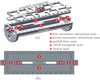
The microwave interrogation cavity is designed based on the rectangular waveguide cavity, according to the U-type interrogation cavity[15] and the ring cavity.[16] The cavity structure is displayed in Fig.
 | Fig. 1. The structure of our microwave interrogation cavity for the rubidium SCAC. (a) Tee isometric side view. The cover and the bracket are moved apart for a clear view of the inner structure. (b) The xy-plane cross-sectional view. |
To determine the dimension of the two interaction zones and the two guided wave zones, we model the interrogation cavity as four rectangular waveguide cavities connected end-to-end as described above and apply the principle of rectangular waveguide cavity in our calculations.[22,23] For single-mode oscillation, each rectangular waveguide cavity must work in transverse electric (TE) mode. We choose the guided wave zones working in TE107 mode and the interaction zones working in TE201 mode according to the SCAC’s overall architecture and its operating characteristics. To ensure that only the TE10p mode propagates in the interrogation cavity, the width a and the height b of the rectangular waveguide should fulfill the following conditions[22,23]


In this work, the dimension of the interaction zones is determined by the rectangular waveguides and the cutoff waveguides. The rubidium cold atoms fly along the y-axis and, thus, the dimension of the atom cloud limits the width of the cutoff waveguide ac. Consequently, we set ac to be 10 mm in our rubidium SCAC, while the thickness of the cutoff waveguide is at = 2.5 mm which is the mechanical strength limit. We then derive the width of each microwave interaction zone working in TE201 mode as a201 = 2a + ac + 2at. Accordingly, we determine the length of each microwave interaction zone to be l201 = 26.684 mm from the following equation
To efficiently suppress the microwave leakage, the attenuation of each cutoff waveguide should be as large as possible to near 77 dB. We calculate the attenuation coefficient for the TE10 mode in the rectangular cutoff waveguide as


With the above calculations, we determined the dimension of each part in the microwave interrogation cavity’s main structure and summarized them in Table
| Table 1. Dimension of each part in the microwave cavity’s main structure. . |
According to Table
| Table 2. The results of eigenmode solving in the microwave interrogation cavity model with finite element analysis software. . |
The microwave interrogation cavity works in the eigenmode named mode 1 while other eigenmodes are suppressed effectively. We then set a port with power of 1 W at the feed-in hole and simulated the electromagnetic field distribution in this cavity. From the modal solution date report, we get the electromagnetic filed distribution as shown in Fig.
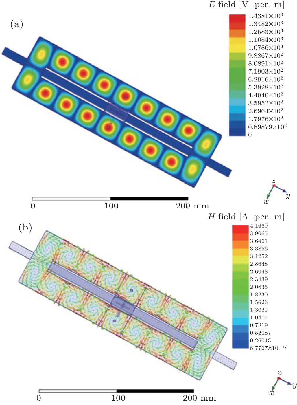 | Fig. 2. The distribution of the electromagnetic field in xy-plane of the new type microwave interrogation cavity. Different colors represent different amplitudes of |
As shown in Fig.


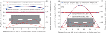
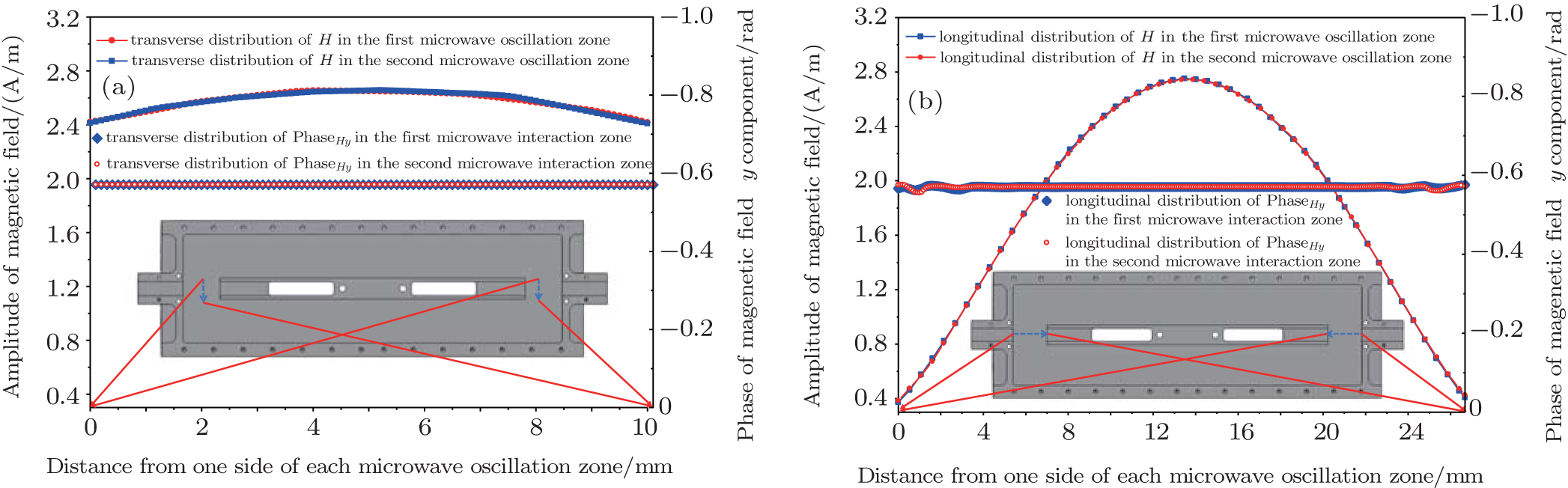 | Fig. 3. The transverse distribution (a) and the longitudinal distribution (b) of H and PhaseHy in each microwave interaction zone. |
In the transverse distribution, as shown in Fig.
In the longitudinal distributions, as shown in Fig.
The simulation results indicate that the interrogation cavity only works in the eigenmode named mode 1, in which the resonance frequency of the cavity is near ν0 and the intrinsic quality factor is large enough for the rubidium SCAC. The electromagnetic field distribution is consistent with our design. What’s more, the differences of the average PhaseHy between different microwave interaction zones are small enough and meet the need of our rubidium SCAC.
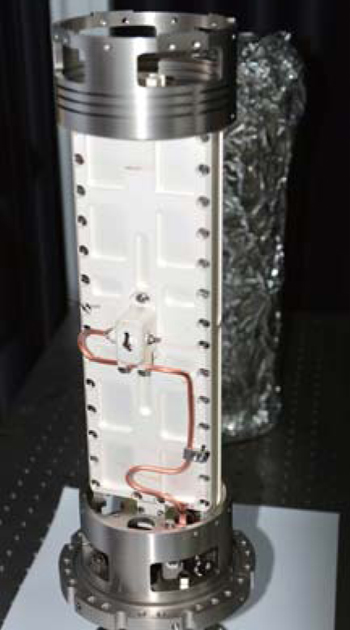
In this work, we have manufactured an interrogation cavity with machining tolerance ±5 μm. A photograph of the cavity is displayed in Fig.
 | Fig. 4. Photograph of the microwave interrogation cavity before being assembled in our rubidium SCAC. |
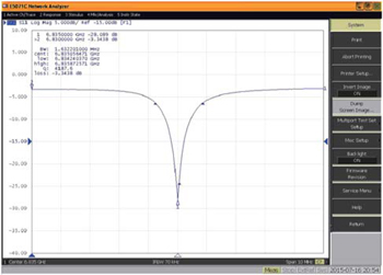
In our SCAC, the interrogation cavity has been integrated in the ultra-high vacuum tube whose vacuum is better than 1.0×10⁻⁸ Pa.[24] We have measured the S parameter and the resonance frequency with a vector network analyzer from 17 °C to 22 °C on-earth. The temperature coefficient of the resonance frequency of the cavity is −0.051 MHz/°C which is consistent with the design basically. The results of the measurement at 22 °C are shown in Fig.
 | Fig. 5. The S parameter of the microwave interrogation cavity measured in the vacuum tube of our rubidium SCAC at 22 °C. |
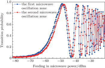
As Rabi et al. mentioned, in addition to the influence of the C-field, the Rabi frequency Ω of the cold atoms’ ground state hyperfine transition in a microwave cavity at the resonance frequency is defined as Ω = μBμ HMW0/ħ, where HMW0 is the intensity of the magnetic field in the microwave field, μB is the Bohr magneton, and μ is the dielectric permeability.[25] Additionally, the Rabi resonance magnetic field intensity HMW0 corresponds to a specific value of the microwave feeding in power PΩ, which is proportional to the square of the magnetic field intensity of the microwave field. Hence, the Rabi frequency Ω is proportional to the square root of PΩ. In order to obtain the information of the magnetic field in each microwave interaction zone, we have measured PΩ of the rubidium cold atoms in each interaction zone with our rubidium SCAC on-earth, in which the C-field has always been set to be 120 nT.
In this experiment, we treated each microwave interaction zone as a single microwave cavity and have measured them respectively. The rubidium cold atoms were launched down from the cooling zone[26] of our rubidium SCAC with a same velocity, 4 m/s, and microwave power was feed in the interrogation cavity with a specific sequence. Finally, the transition probability of the rubidium cold atoms was derived from time-of-flight (TOF) signals[8,9] during the rubidium cold atoms passing through the detection zone. The microwave frequency was fixed at ν0, but its power was changed step by step by 0.25 dBm. When the first interaction zone was being measured, the microwave power was shut down during the flight of the rubidium cold atoms over the second interaction zone, and vice versa.
 | Fig. 6. The result of the Rabi frequency measurements. The vertical axis indicates the transition probability of cold atoms and the horizontal axis indicates the microwave feeding power. |
As results, we obtained the Rabi oscillation curves of each microwave interaction zone in which the transition probability of the rubidium cold atoms changes with the feed-in power as shown in Fig.


In this paper, we have presented a microwave interrogation cavity which was designed for the rubidium SCAC. This cavity can be considered as four small cavities connected end-to-end, with two of them as guided wave zones and the other two as microwave interaction zones. The guided wave zones work in TE107 mode and the microwave interaction zones work in TE201 mode, ensuring that the electromagnetic field distribution is suitable for the interrogation of the rubidium cold atoms. There are four cutoff waveguides which guarantee the microwave oscillations are terminated effectively during the rubidium atoms’ free evolution. Accordingly, in this interrogation cavity, forward flying rubidium cold atoms can successively interact with the two microwave pulses separated by a zero electromagnetic field area.
Furthermore, we have simulated this interrogation cavity with finite element analysis software and presented its characteristics. The magnetic fields in the two microwave interaction zones distribute in a highly consistent manner along the trajectory of the cold atoms. The longitudinal average phase differences of the y component of the magnetic field is 8.6×10⁻⁶ rad, which is small enough for the rubidium SCAC.
Finally, we have manufactured a microwave interrogation cavity and measured its S parameter. The loaded quality factor is about 4200 and the resonance frequency is 6.835056471 GHz which is near the rubidium cold atom’s resonance frequency 6.834682610 GHz in our SCAC. Moreover, we have measured the Rabi frequency in each microwave interaction zone and derived that Ω10 = Ω20 when the rubidium SCAC works in space, which indicates that the magnetic field is distributed in the same manner in the two microwave interaction zones.
In all, this interrogation cavity is designed based on the rectangular waveguide cavity principle with a compromise of 
| 1 | |
| 2 | |
| 3 | |
| 4 | |
| 5 | |
| 6 | |
| 7 | |
| 8 | |
| 9 | |
| 10 | |
| 11 | |
| 12 | |
| 13 | |
| 14 | |
| 15 | |
| 16 | |
| 17 | |
| 18 | |
| 19 | |
| 20 | |
| 21 | |
| 22 | |
| 23 | |
| 24 | |
| 25 | |
| 26 | |
| 27 |