Effects of Mg doping in the quantum barriers on the efficiency droop of GaN based light emitting diodes
Liu Yang1, Yang Yongchun1, 2, †,
School of Resource and Environmental Science, Lanzhou University, Lanzhou 730000, China
Key Laboratory of West China's Enviromental Science, Lanzhou 730000, China


† Corresponding author. E-mail: yangych@lzu.edu.cn

Project supported by the National Natural Science Foundation of China (Grant No. 41171143).

Abstract
Abstract

The effects of Mg doping in the quantum barriers (QBs) on the efficiency droop of GaN based light emitting diodes (LEDs) were investigated through a duel wavelength method. Barrier Mg doping would lead to the enhanced hole transportation and reduced polarization field in the quantum wells (QWs), both may reduce the efficiency droop. However, heavy Mg doping in the QBs would strongly deteriorate the crystal quality of the QWs grown after the doped QB. When increasing the injection current, the carriers would escape from the QWs between n-GaN and the doped QB and recombine non-radiatively in the QWs grown after the doped QB, leading to a serious efficiency droop.

1. Introduction

The commercialization of GaN base light emitting diodes (LEDs) has attracted much attention in recent years.[13] As LEDs are energy saving and have long life time, they have been considered as an ideal candidate for the next generation lighting source.[4,5] What is more, LEDs also open gates for many new applications, such as agriculture,[6] visible light communication,[7,8] and intelligent lighting.[9,10] One of the most challenging obstacles for the further development of the LED industry is the decreased LED performance under high injection currents, namely, efficiency droop.[11] The asymmetry of carrier transport is considered as an important factor of this issue.[12,13] For III-nitride materials, the hole concentration in the p-type layer is much lower than the electron concentration in the n-type layer, what is more, the hole mobility is much lower than the electron mobility. The low transportation ability of holes makes most of the carriers accumulated in the quantum wells (QWs) close to the p-GaN layer. The accumulation of carriers in the QWs close to p-GaN would induce not only the strong carrier leakage and Auger recombination, but also the low recombination efficiency in the QWs close to the n-GaN layer, both would lead to the efficiency droop.

Mg doping in the active layers has been proved to be useful for promoting hole transportation towards the n-GaN side, thus leading to the reduced efficiency droop.[1417] However, even it is well known that the heavy Mg doping would induce non-radiative recombination centers in QWs and then deteriorate the peak efficiency of LED chips, few works have focused on its effect on the efficiency droop. Further investigation on the effect of Mg doping in the QBs on the efficiency droop of LEDs would give us deep insight into the phenomenon of efficiency droop.

In this paper, the effects of Mg doping in the QBs on the efficiency droop of LEDs are investigate through a dual wavelength method. It is found that only mediate Mg doping in the QB could lead to the reduced efficiency droop. Mg doping in the QB could enhance the hole transportation and reduce the quantum confined Stark effect (QCSE), both would modify the efficiency droop phenomenon. However, heavy Mg doping would seriously deteriorate the crystal quality of QWs grown after the doped QB. Under high injection currents, the carriers would flow over the doped QB and recombine non-radiatively in the following QW, leading to a serious efficiency droop.

2. Experimental procedures

In the experiment, three samples were prepared. All samples were grown on c-plane sapphire substrates by metal organic chemical vapor deposition (MOCVD). Thrimethylgallium (TMGa), thrimethylindum (TMIn), ammonia (NH3), biscyclopentadienylmagnesium (CP2Mg), and silane (SiH4) were used as gallium, indium, nitrogen, p-type and n-type dopant sources, respectively. After the deposition of the low temperature nucleation layer, the temperature was increased to 1050 °C to grow the 4-μm undoped and 2-μm Si doped GaN layers. The active region consisted of five periods of InGaN/GaN QWs. Four QWs close to the n-GaN side were designed to generate blue light, with the growth temperature of 730 °C. The QW close to the p-GaN side was designed to generate green light, with the growth temperature of 700 °C. All QBs were grown at the temperature of 830 °C. Then the 200 nm p-GaN layer was grown at 950 °C. All LED chips were fabricated with the standard lateral structure and the size of 250 μm × 500 μm. Cr/Pt/Au of the thicknesses of 70 nm/40 nm/1440 nm were evaporated as both the p-type and n-type electrodes. Then the metal contacts were annealed in N2 at 250 °C for 15 min under the atmosphere pressure. Photoluminescence (PL) measurement was carried out using the 325 nm line of a He–Cd laser. The electroluminescence (EL) of the packaged LEDs was measured in an integrating sphere at 300 K in a cw current mode.

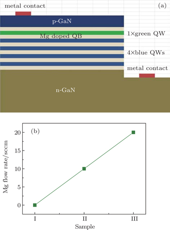
The schematic LED structure is shown in Fig. 1(a). Three samples are identical except for the Mg doping concentration in the QB between blue QWs and green QW. The Mg doping profiles of the three samples are shown in Fig. 1(b). For sample I, no Mg source was used. While for samples II and III, the Mg flow rate was 10 sccm and 20 sccm, respectively, when growing the QB between blue QWs and green QW. According to our previous results, the Mg incorporation of sample II is about 1 × 1019 cm−3.

Fig. 1. (a) Schematic LED structure used in the experiment. (b) The Mg doping profiles of the three samples.
3. Results and discussion

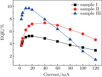
Figure 2 presents the external quantum efficiency (EQE) as a function of the injection current for the three samples. With Mg doping, sample II shows an enhanced peak efficiency and a reduced efficiency droop compared with sample I. For sample III, with increasing Mg doping concentration, the peak efficiency continues to increase. However, it shows a more serious efficiency droop compared with samples I and II. In order to gain deeper insights into the effects of the Mg doping on the efficiency of LED devices, the EL and PL experiments were conducted, and the results are discussed in the following.

Fig. 2. EQE as a function of the injection current for LED samples I, II, and III.

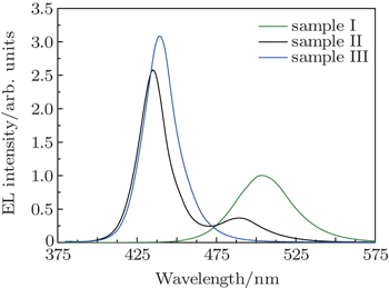
The EL spectra of the samples at the injection current of 30 mA are shown in Fig. 3. From sample I to sample III, the luminescence spectra gradually shift from green to blue, indicating the enhanced recombination efficiency in the QWs close to the n-GaN side. The previous research proposed that heavy Mg doping in the QBs would strongly enhance the hole injection into the QWs close to the n-GaN side, thus suppress the emission in the QWs close to the p-GaN side.[14] From simulation results by APSYS, it was found that the carriers accumulate more in the QWs close to the n-GaN side rather than in the QWs close to the p-GaN side with increasing Mg doping concentration. However, due to the high mobility of electrons, it is very hard to block all electrons in the QWs close to the n-GaN side through barrier Mg doping, which was also seen in the APSYS results. Thus we believe that other mechanisms may also have effects on this phenomenon.

Fig. 3. EL spectra of samples I, II, and III at the injection current of 30 mA.

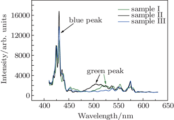
Unlike the EL measurements, the PL measurements excite the electron–hole pairs optically, thus excluding the effects of carrier electrical transportation on light emission. The PL spectra of the samples are shown in Fig. 4. All samples show the narrow and high intensity blue emission band. The growth temperature is higher for the blue QWs, which leads to the better crystal quality, thus the blue peaks are higher and narrower than the green ones. The lattice mismatch between blue QWs and QBs is smaller than the green one, therefore, the QCSE is smaller for the blue QWs, which would also lead to the higher recombination efficiency. What is more, there are more blue QWs than the green ones in our experiments. All of these factors would lead to the high PL intensity of the blue band. From Fig. 4, it is clear that the blue band consists of several peaks. This phenomenon has several explanations, for example, the indium fluctuation in the QWs, the phonon satellite peaks, and the Fabry–Perot interference. We believe that these peaks are related with the Fabry–Perot interference because the peak wavelength variations between all neighboring peaks are almost identical, which is a feature of the Fabry–Perot interference.[18] By using the method given by Hums et al.,[18] the cavity thickness of the Fabry–Perot interference for samples I, II, and III is calculated to be about 6.32 μm, 6.56 μm, and 5.89 μm, respectively. They are in agreement with the total thicknesses of the epilayers designed in the experiment, indicating that these peaks are caused by the Fabry–Perot interference between the epilayer/substrate and the epilayer/air interface.

Fig. 4. PL spectra of samples I, II, and III.

From Fig. 4, it can be seen that further increasing the Mg flow rate to 20 sccm would lead to the disappearance of the green peaks. It was reported that mediate Mg doping could promote the lateral growth of GaN layers and thus increase the crystal quality, as Mg could act as a surfactant.[19] However, heavy Mg doping could lead to the surface segregation of Mg atoms and deteriorate the crystal quality.[20] It is also well known that the Mg atoms in the QWs would induce non-radiative recombination centers. Thus the strong diffusion and transient effects of Mg atoms under heavy doping conditions may be other reasons for the disappearance of the green peaks.[21,22] It is reported that the Mg atoms would diffuse at a temperature higher than 925 °C.[22] Considering that the growth of Mg doped QB and green QW was followed by the growth of the p-GaN layer at 950 °C for 20 min in our experiment, and no undoped spacer layer was added between the Mg doped QB and the green QW, we believe that the Mg diffusion may have a strong effect on the luminescence efficiency in the green QW. The transient effect of Mg atoms is that the Mg atoms may adsorb onto the internal reactor walls and subsequently desorb, which may cause unintentional Mg doping in the layers grown after the Mg doped layer,[22] for example, the green QW in our experiment. Further experiments with the secondary-ion mass spectrometry (SIMS) are being conducted to clarify the Mg profiles in the samples and would be reported later. Together with the EL spectra, we think that the reduction of the green peak intensity with Mg doping is mainly due to the enhanced carrier injection into the blue QWs. While with increasing Mg doping, the crystal quality of the green QW is deteriorated, resulting in the disappearance of the green emission.

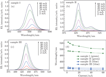
There is another feature in the PL spectrum. When the Mg flow rate is increased from 0 to 10 sccm, the green peak shows a large blue shift. As the green QW is grown next to the doped barrier, this phenomenon may be explained by the reduction of the polarization field in the QWs by Mg doping. To confirm the explanation, the EL spectra of the samples with different injection currents are shown in Fig. 5. The dependences of wavelength of the green peak in sample I, the green and blue peaks in sample II, and the blue peak in sample III on the injection current are shown in Fig. 5(d). Compared with that in sample I, the wavelength of the green peak in sample II is shorter and the wavelength shift of the green peak with increasing injection current is smaller. Both indicate the reduction of the polarization field and the QCSE in the QWs. The reduction of the polarization field in the QWs may result from the free carrier screening. Doping in the barriers could increase the hole concentration in the QWs. These holes would accumulate into the wells with the lowest potential, i.e., the interface of QBs and QWs, thus screen the interface negative charge and reduce the polarization field. The screening of the polarization field by Si doping in the barriers is well accepted as Si doping can offer enough free carriers.[23,24] Our works together with the previous one[25] show that Mg doping in the QBs also has strong effects on the polarization field. The reduction of the QCSE caused by Mg doping may also lead to the reduced efficiency droop. Thus the reduced efficiency droop of sample II compared with sample I may result from the enhanced hole transportation and the reduced polarization field. While the enhanced peak efficiency of sample II is due to the transformation from green emission to blue emission as the crystal quality is improved and the QCSE is smaller for the blue QWs.

Fig. 5. EL spectra of (a) sample I, (b) sample II, and (c) sample III with different injection currents. (d) The dependences of wavelength of the green peak in sample I, the green and blue peaks in sample II, and the blue peak in sample III on the injection current.

The wavelength shifts of the blue peaks in both samples II and III are almost the same, indicating that the QCSE in both samples are almost identical. The wavelength of the blue peaks of sample III is a bit longer than that of sample II, which is the result of the run to run variations considering the similar QCSE in both samples. As the blue QWs with better crystal quality contribute more to the luminescence of sample III, the peak efficiency of sample III is the highest. As we discussed above, the crystal quality of the green QW is deteriorated and the radiative recombination efficiency of the green QW is quite low in sample III. For the blue QWs only, the carrier distribution condition is not modified in sample III. When increasing the injection current, the carriers would escape from the blue QWs and recombine non-radiatively in the green QW, leading to the serious efficiency droop. As the blue QWs with better crystal quality and smaller QCSE contribute more in sample III, the peak efficiency of sample III is the highest. Thus it should be noted that the Mg doping concentration in the barriers must be carefully modified to realize the uniform light emission from all QWs and then the reduced efficiency droop.

4. Conclusion

We investigated the effects of barrier Mg doping on the efficiency droop of LEDs. The efficiency droop is only reduced for mediate Mg doping samples. Mediate Mg doping could enhance the hole transportation and reduce the QCSE, thus lead to the reduced efficiency droop. Heavy Mg doping would seriously deteriorate the crystal quality of the QWs grown after the doped QB. As a result, the carriers would flow over the doped QB and recombine non-radiatively in the following QW, leading to the serious efficiency droop under high injection currents.

Reference
1Ozgur ULiu HLi XNi XMorko H 2010 Proc. IEEE 98 1180
2Nakamura S 1998 Science 281 956
3Schubert E FHunt N E JMicovic MMalik R JSivco D LCho A YZydzik G J 1994 Science 265 943
4Pimputkar SSpeck J SDenBaars S PNakamura S 2009 Nat. Photon. 3 180
5Rogach A LGaponik NLupton J MBertoni CGallardo D EDunn SPira N LPaderi MRepetto PRomanov S GDwyer C OTorres C M SEychmüller A 2008 Angew. Chem. Int. Edit. 47 6538
6Olvera-Gonzalez EAlaniz-Lumbreras DIvanov-Tsonchev RVilla-Hernandez JOlvera-Olvera CGonzalez-Ramirez EAraiza-Esquivela MTorres-Argüellesd VCastañoc V l 2013 Comput. Electron. Agr. 92 48
7Komine TNakagawa M 2004 IEEE Trans. Consum. Electron. 50 100
8Vucic JKottke CNerreter SLanger K DWalewski J W2010J. Lightw. Technol.283512
9Guo LEloholma MHalonen L2007Int. Rev. Electron. Eng. I214
10Byun JHong ILee BPark S. 2013 IEEE T. Consum. Electron. 59 70
11Zhao Y KLi Y FHuang Y PWang HSu X LDing WYun F 2015 Chin. Phys. 24 056806
12Meyaard D SLin G-BShan QCho JSchubert E FShim HKim M HSone C 2011 Appl. Phys. Lett. 99 251115
13Meyaard D SLin G BCho JSchubert E FShim HHan S HKim M HSone CKim Y S 2013 Appl. Phys. Lett. 102 251114
14Si ZWei T BMa JYan J CWei X CLu H XFu B LZhu S XLiu ZWang J XLi J M 2013 ECS Solid. State Lett. 2 R37
15Ji YZhang Z HTan S TJu Z GKyaw ZHasanov NLiu WSun X WDemir H V 2013 Opt. Lett. 38 202
16Huang C YYan QZhao YFujito KFeezell DVan de Walle C GSpeck J SDenBaars S PNakamura S 2011 Appl. Phys. Lett. 99 141114
17Han S HCho C YLee S JPark T YKim T HPark S HKang S WKim J WKim Y CPark S J 2010 Appl. Phys. Lett. 96 051113
18Hums CFinger THempel TChristen JDadgar AHoffmann AKrost A 2007 J. Appl. Phys. 101 033103
19Beaumont BHaffouz SGibart P. 1998 Appl. Phys. Lett. 72 921
20Namkoong GTrybus ELee K KMoseley MDoolittle W ALook D C. 2008 Appl. Phys. Lett. 93 172112
21Köhler KStephan TPerona AWiegert JMaier MKunzer MWagner J 2005 J. Appl. Phys. 97 104914
22Köhler KGutt RWiegert JKirste L 2013 J. Appl. Phys. 113 073514
23Wu XLiu JXiong CZhang JQuan ZMao QJiang F 2013 J. Appl. Phys. 114 103102
24Zhiting LRui HGuoqiang LShuguang Z 2015 Jpn. J. Appl. Phys. 54 022102
25Zhang NLiu ZSi ZRen PWang X DFeng X XDong PDu C XZhu S XFu B LLu H XLi J MWang J X 2013 Chin. Phys. Lett. 30 087101