


Pressure induced magnetic and semiconductor–metal phase transitions in Cr2MoO6
[Guo San-Dong†,  ]
]
]
|
|


† Corresponding author. E-mail:
Project supported by the Fundamental Research Funds for the Central Universities, China (Grant No. 2015XKMS073).
We investigate magnetic ordering and electronic structures of Cr2MoO6 under hydrostatic pressure. To overcome the band gap problem, the modified Becke and Johnson exchange potential is used to investigate the electronic structures of Cr2MoO6. The insulating nature at the experimental crystal structure is produced, with a band gap of 1.04 eV, and the magnetic moment of the Cr atom is 2.50 μB, compared to an experimental value of about 2.47 μB. The calculated results show that an antiferromagnetic inter-bilayer coupling–ferromagnetic intra-bilayer coupling to a ferromagnetic inter-bilayer coupling–antiferromagnetic intra-bilayer coupling phase transition is produced with the pressure increasing. The magnetic phase transition is simultaneously accompanied by a semiconductor–metal phase transition. The magnetic phase transition can be explained by the Mo–O hybridization strength, and ferromagnetic coupling between two Cr atoms can be understood by empty Mo-d bands perturbing the nearest O-p orbital.
Many interesting phenomena can be produced by using the pressure, such as semiconductor to metal,[1] conventional insulator to topological insulator,[2–4] and ferromagnetic semiconductor to spin gapless semiconductor[5] transitions. Exploring the magnetic coupling mechanism in magnetic materials has always been a fundamental topic.[6–10] The exchange coupling in transition-metal oxides can be understood by the superexchange interaction,[6] and the double-exchange mechanism[7] which can explain the metallicity and ferromagnetic coupling in the mixed-valence Mn compounds.
The inverse-trirutile compounds Cr2XO6 (X = W, Te, Mo) with space group P42/mnm are antiferromagnetic insulators, in which the antiferromagnetic superexchange interaction cannot give an outright explanation about the magnetic coupling of Cr atoms.[11–13] Their magnetic structures, namely the Cr–O–Cr magnetic coupling, depend on the X atom. In Cr2XO6 (X = W, Mo), the inter-layer Cr atoms are antiferromagnetically coupled, while the neighboring intra-bilayer Cr atoms are ferromagnetically aligned. However, the neighboring intra-bilayer Cr atoms are antiferromagnetically aligned in Cr2TeO6. The novel intra-bilayer ferromagnetic coupling can be explained by assuming a virtual transfer between O and W (Mo) atoms which tunes the orbital hybridization between Cr-d and O-p orbitals.[12,13]
Here, we investigate magnetic ordering change of inter-bilayer and intra-bilayer Cr atoms of Cr2MoO6 under hydrostatic pressure. The electronic structures are calculated by using Tran and Blaha’s modified Becke and Johnson (mBJ) exchange potential, which describes properly the gaps and positions of d electrons of Cr2MoO6. The calculated results show that the inter-bilayer magnetic coupling changes from antiferromagnetic coupling to ferromagnetic, and the intra-bilayer coupling changes from ferromagnetic ordering to antiferromagnetic. When the magnetic phase transition happens, a semiconductor–metal phase transition also occurs. The magnetic phase transition can be understood by the intra-bilayer ferromagnetic coupling mechanism proposed by Zhu et al. in Refs. [12] and [13].
The rest of the paper is organized as follows. In the next section, we shall give our computational details. In Section 3, we shall present our main calculated results and analysis. Finally, we shall give our conclusion in Section 4.
We use the full-potential linearized augmented-plane-waves method within the density functional theory (DFT)[14,15] as implemented in the package WIEN2k.[16] We use the mBJ exchange potential plus local density approximation (LDA) correlation potential for the exchange–correlation potential[17] to do our main electronic structure calculations, and use the popular generalized gradient approximation of Perdew, Burke, and Ernzerhof (GGA-PBE)[18] to optimize the internal position parameters with a force standard of 2 mRy/a.u. The full relativistic effects are calculated with the Dirac equations for the core states, and the scalar relativistic approximation is used for the valence states.[19–21] The atomic sphere radii of Cr, Mo, and O are chosen to be 1.82 a.u., 1.78 a.u., and 1.61 a.u., respectively. We use a 11 × 11 × 6 Monkhorst–Pack k-points grid for the self-consistent calculation and make harmonic expansion up to lmax = 10 in each of the atomic spheres, and set Rmtkmax = 7. The self-consistent calculations are considered to be converged when the integration of the absolute charge-density difference between the input and the output electron densities is less than 0.0001|e| per formula unit, where e is the electron charge.
The Cr2MoO6 has an inverse-trirutile structure with the lattice parameters a = b = 4.58717 Å and c = 8.81138 Å at T = 4 K, which undergoes a paramagnetic–antiferromagnetic transition at T = 93 K with inter-bilayer antiferromagnetic coupling and intra-bilayer ferromagnetic coupling.[13] The sketch map of Cr2MoO6 crystal structure is shown in Fig.
 | Fig. 1. The sketch map of Cr2MoO6 crystal structure. The black balls, blue balls, and red balls represent Cr atoms, Mo atoms, and O atoms, respectively. The Cr bilayers are separated by a Mo layer. The O atoms connecting inter-bilayer Cr atoms are marked as O1, and the O atoms connecting intra-bilayer Cr atoms are marked as O2. The labeled Mo1 and Mo2 atoms are equivalent. |
 | Fig. 2. The magnetic energy differences as a function of V/Vexp (AF–F magnetic configuration is used as a reference). The points represent calculated values, and the lines are obtained by linear or curve fitting. The inset shows the energy band gap as a function of V/Vexp. |
As is well known, GGA generally does not accurately describe the position of transition-metal d electrons, and underestimates the gaps of magnetic insulators. The improved mBJ exchange potential has been proved to be very effective to describe electronic structures and gaps of magnetic insulators.[5,22–25] The projected spin-dependent densities of states of Cr2MoO6 calculated by using mBJ and GGA are shown in Fig.
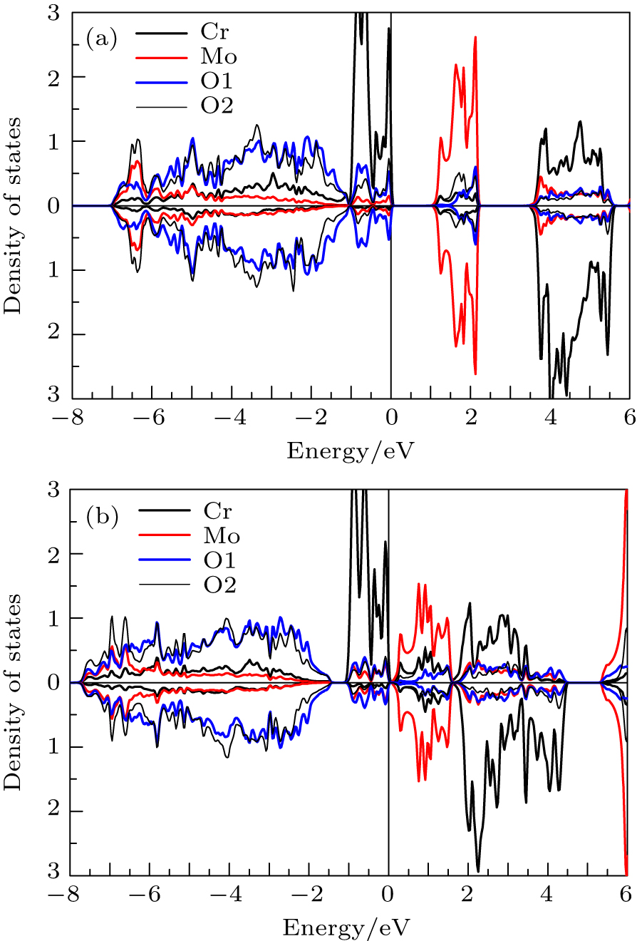 | Fig. 3. The partial spin-dependent densities of states of Cr2MoO6 projected in Cr, Mo, O1, and O2 atom spheres by using (a) mBJ and (b) GGA, respectively. |
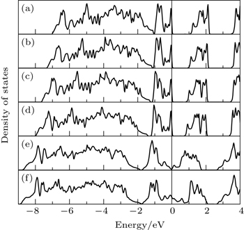
 | Fig. 4. The total densities of states of Cr2MoO6 with (a)–(d) AF–F and (e)–(f) F–AF magnetic configurations by using mBJ. Panels (a)–(f) correspond to points A–F, respectively. |
In Refs. [12] and [13], the mechanism of the intra-bilayer ferromagnetic coupling was explained as follows. The virtual hopping of an O2-p electron to the empty Mo2-d states makes the O2-p state partially occupied, which creates a virtual hole in the O-p band and leads to ferromagnetic coupling between intra-bilayer Cr atoms. The hybridization strength between O1 (O2) and Mo1 (Mo2) is a key factor that determines the inter-bilayer (intra-bilayer) magnetic coupling. Since the distance between O1 and Mo1 and that between O2 and Mo2 control the hybridization strength, we plot the bond lengths of O1–Mo1 and O2–Mo2 (and their average values) as a function of V/Vexp with AF–F and F–AF magnetic configurations in Fig.
 | Fig. 5. The bond lengths of O1–Mo1 (d1) and O2–Mo2 (d2) as a function of V/Vexp with (a) AF–F and (b) F–AF magnetic configurations, and (c) their average values. |
To see clearly the magnetic ordering, we show the magnetization density distributions of Cr2MoO6 at points A (AF–F) and F (F–AF) with energy ranging from −8 eV to the Fermi level in Fig.
 | Fig. 6. The magnetization density distributions of Cr2MoO6 at (a) A (AF–F) and (b) F (F–AF) points. The plane is defined by a Cr1–Cr2–Cr3 triangle. The actual magnetization density is −0.01–0.01 |e|/Bohr3 and the density increment is 0.00067 |e|/Bohr3. The blue, black, and red lines stand for positive, negative, and zero values, respectively. |
The improved mBJ exchange potential is used to investigate the electronic structures of Cr2MoO6 under pressure. The x-ray emission spectra of delafossite type oxide CuFeO2 (magnetic insulator) calculated by using mBJ are quite compatible with the experimental data.[22] The mBJ gives an appropriate description for HgCr2Se4, CdCr2S4, and CdCr2Se4 (magnetic insulator), and the mBJ gaps agree well with the experimental values.[5] So, the mBJ may be suitable to study the electronic structures of Cr2MoO6 under pressure.
We investigate the change of magnetic ordering and gaps of Cr2MoO6 under pressure. The calculated results show that magnetic and semiconductor–metal phase transitions in Cr2MoO6 are caused by the pressure. With the increasing pressure, the AF–F magnetic configuration transforms into the F–AF one, followed by a semiconductor–metal phase transition. The proposed mechanism of intra-bilayer ferromagnetic coupling in Cr2MoO6[12,13] can be used to understand the magnetic phase transition, and the Mo–O hybridization strength plays a key role in determining the inter-bilayer and intra-bilayer magnetic ordering. We use the trend of bond lengths of Mo1–O1 and Mo2–O2 under pressure to explain the magnetic phase transition. The idea that empty Mo-d states by perturbing the O-p states can give rise to ferromagnetic coupling between two Cr atoms is further confirmed.
| 1 | |
| 2 | |
| 3 | |
| 4 | |
| 5 | |
| 6 | |
| 7 | |
| 8 | |
| 9 | |
| 10 | |
| 11 | |
| 12 | |
| 13 | |
| 14 | |
| 15 | |
| 16 | |
| 17 | |
| 18 | |
| 19 | |
| 20 | |
| 21 | |
| 22 | |
| 23 | |
| 24 | |
| 25 |