† Corresponding author. E-mail:
Project supported by the Creative Plan Project of Nanjing Forest Police College, China (Grant Nos. 201512213045xy and 201512213007x).
Motivated by recent experimental observations of metallic conduction in the quasi-two-dimensional SrFeO2, we study the epitaxial strain effect on the formation and electronic structures of oxygen vacancy (Vo) by first-principles calculations. The bulk SrFeO2 is found to have the G-type antiferromagnetic ordering (G-AFM) at zero strain, which agrees with the experiment. Under compressive strain the bulk SrFeO2 keeps the G-AFM and has the trend of Mott insulator-metal transition. Different from most of the previous similar work about the strain effect on Vo, both the tensile strain and the compressive strain enhance the Vo formation. It is found that the competitions between the band energies and the electrostatic interactions are the dominant mechanisms in determining the Vo formation. We confirm that the Vo in SrFeO2 would induce the n-type conductivity where the donor levels are occupied by the delocalized dx2−y2 electrons. It is suggested that the vanishing of n-type conductivity observed by the Hall measurement on the strained films are caused by the shift of donor levels into the conduction band. These results would provide insightful information for the realization of metallic conduction in SrFeO2.
Transition-metal oxides (TMOs) have been widely studied because of the peculiar physics and the novel functions found in these materials. Among these TMOs, the Fe related oxides are one of the most extensively studied systems. Here, we focus on the newly synthesized compound SrFeO2, which is the first ternary earth alkaline oxoferrate.[1,2] Unlike the conventional ABO3 perovskite structure, the lack of apical oxygen made SrFeO2 have the infinite-layer structure with a square-planar coordination (Fig. 


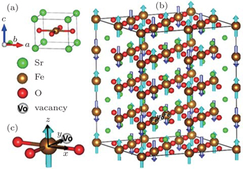 | Fig. 1. (a) The four-atom primitive cell of tetragonal SrFeO2. (b) The  |
On the other hand, the functional behavior of TMOs can be improved when they are prepared as thin films. The enhanced behavior is usually attributed to the strain introduced by the substrate with different lattice constants. The epitaxial strain would affect the bond lengths and/or the bond angles, which finally changes the electronic structures, the magnetic properties and so on. Importantly, as SrFeO2 was isotypic with SrCuO2 where the high-Tc could be induced by carrier doping,[14] the researchers concentrated on the realization of metallic conduction inSrFeO2 by chemical substitution.[15–18] However, the obtained compounds were still insulators. Recently, the single-crystalline epitaxial SrFeO2 thin films were grown on the perovskite substrates with various lattice constants.[19] Metallic conduction was found on the lattice-matched KTaO3 (001) substrate, and Hall measurements showed that the conduction carriers are n-type. Katayama et al. confirmed that the metallic conduction was an intrinsic property of SrFeO2 film and speculated the carriers were supplied by Vo as there were Vo’s in their films. However, they did not observe n-type conductivity on the lattice-mismatched substrates. Thus, it is worth examining whether the Vo of SrFeO2 can induce the n-type conductivity and how the behavior of Vo is affected by the epitaxial strain. In this work, we provide a first-principles survey of the following questions. (i) Do the bulk SrFeO2 have a magnetic transition under strain? (ii) How difficult is it to form a Vo in SrFeO2? (iii) Does Vo act as electron donors to mobile conducting states at the Fermi level in SrFeO2? (iv) If the Vo in SrFeO2 induces the n-type conductivity, how does the strain affect the performance of the n-type conductivity?
The remainder of this paper is organized as follows. In Section 2 we describe the calculation method used throughout this work. In Section 3 we first study the properties of bulk SrFeO2 under strain, then discuss the strain induced changes of formation energy of Vo. After that we present our results for the electronic structures of Vo under strain. Finally, the conclusion is given in Section 4.
First-principles calculations are performed using the projector augmented wave (PAW) method,[20] as implemented in the Vienna ab initio simulation package (VASP).[21,22] The exchange–correlation functional is treated by the generalized gradient approximation (GGA).[23] The Hubbard U correction[24] is applied to Fe 3d electrons. We use Ueff = 4 eV[5] to reproduce the experimentally determined electronic and magnetic properties of bulk SrFeO2. The valence electron configurations are Sr (4s24p65s2), Fe (3p63d63s2), and O (2s2p4). To model the Vo, we construct a 
The formation energy (Eform) of Vo is calculated according to the following formula: Eform(ɛ, Vo) = Etot,Vo − Etot,bulk+μo, where μo is the chemical potential of oxygen. The Etot,bulk and Etot,Vo denote the total energy of the bulk simulation cell and that containing Vo, respectively.
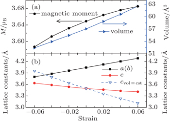
We first reproduce the experimentally determined properties of bulk SrFeO2. As shown in Tables 1 and 2, the calculated lattice constants, band gap, and magnetic moment overall agree with the experiment and previous theoretical work.[5] Then we study the strain effect on the bulk SrFeO2. The SrFeO2 thin film may be grown on various substrates. Except for the lattice-matched KTaO3 substrate,[1,2,19] the practical substrate lattice constants are smaller than 3.99 Å, such as 3.91 Å (SrTiO3),[19,28] 3.79 Å (LaAlO3),[29] 3.94 Å (DyScO3),[19,30] etc. Therefore, the compressive strains are introduced up to −0.06. The tensile strains are also introduced for comparison. To determine the magnetic orderings under strain, we consider the A-AFM, C-AFM, G-AFM, and FM. As shown in Fig. 

| Table 1. The calculated properties of bulk SrFeO2 without strain. For comparison, the experimental values and previous theoretical values are also provided. The units of a(b) and c are Å. The units of MFe and Egap are μB and eV, respectively. . |
| Table 2. The calculated total energies (meV/f.u.) of bulk SrFeO2 at different strains. EG, EA, EC, and EF denote the total energies of G-AFM, A-AFM, C-AFM, and FM, respectively. . |
 | Fig. 2. Schematic view of different magnetic orderings. For clarity the  |
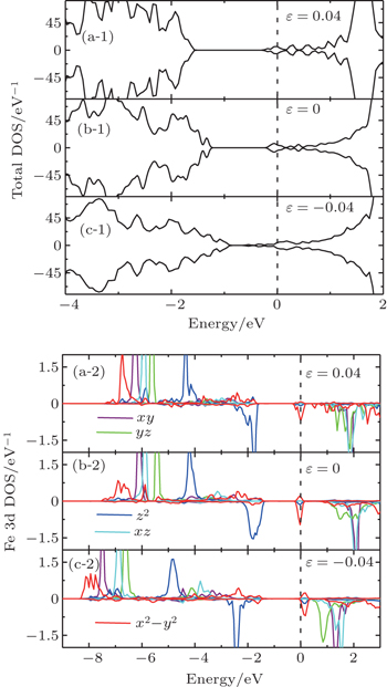
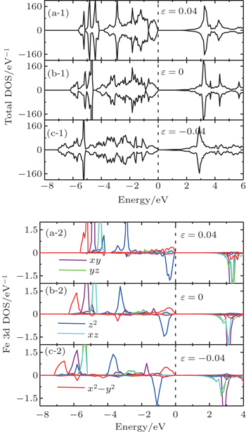 | Fig. 4. (a-1), (b-1), (c-1), and (d-1) Total DOS and (a-2), (b-2), (c-2), and (d-2) orbital-resolved DOS of bulk SrFeO2. |
On the contrary, the compressive strain makes the dyzdxz states in the CB come nearer with respect to the valence band maximum (VBM), thus the band gap decreases with increasing compressive strain. At the same time, the separation between the dx2−y2 states and the down dz2 states becomes larger around the Fermi level. When the compressive strain increases up to −0.06, the band gap nearly comes to zero (not shown), the dx2−y2 states also come nearer with respect to the Fermi level. A Mott-type insulator–metal transition (IMT), where the dx2−y2 orbital would cross the Fermi level, is expected if we continue to increase the compressive strain, which is similar to the case of IMT at hydrostatic pressure.[6,31] Note that tests are performed at −0.08 and −0.1 strain, and we find the occupations of dx2−y2 states at the Fermi level, but the large strain values which may not be very practical are beyond the scope of the present work. Figure
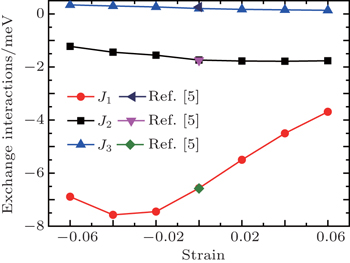 | Fig. 5. Exchange interactions with respect to the strain. The data (zero strain) of Ref. [5] are provided for comparison. |
We consider the intralayer NN exchange interactions J1, the interlayer NN exchange interactions J2, and the interlayer next nearest neighbor (NNN) exchange interactions J3. The calculated values at zero strain agree well with previous work.[5] The exchange interactions show the anisotropic behavior where J1 is about three times larger than J2, indicating the dominant role of intralayer superexchange interactions. It is interesting to note that the strength (absolute value) of J1 shows a decrease trend at −0.06 strain. This may imply the instability of G-AFM at very large strain as the AFM–FM transition has been found at high pressure.[6,31]
In the tetragonal SrFeO2 structure (see Fig.
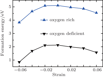
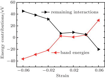
Generally speaking, the increase in bond lengths and volumes associated with the tensile strain is likely to decrease the formation energies of Vo due to the decreased Coulomb interactions between ions.[37] It is also believed that the remaining electrons caused by Vo would strengthen the pressure of the electron gas and thus induce an intrinsic compressive stress in the unrelaxed lattice.[38] Therefore, the formation energy is expected to increase in the compressive strain range, and the tensile strain would relieve the intrinsic compressive stress and promote to create the Vo, which has been widely reported in previous similar work.[39,40] As expected, the Vo formation energy decreases with increasing tensile strain, as shown in Fig.
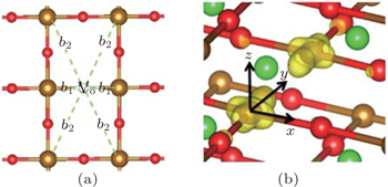 | Fig. 7. (a) Local structure around Vo. b1 and b2 are the bond lengths (Å). (b) Partial charge density of the defect levels shown in Fig. |
| Table 3. Structural relaxations around Vo. Δ denotes the changes of b1(b2) before and after relaxations. The units of b1(b2) are Å. . |
As shown in Fig.
In summary, we study the epitaxial strain effect on the formation and electronic structures of Vo in SrFeO2 by first-principles calculations. It is found that the bulk SrFeO2 has the G-AFM at zero strain, which agrees with the experiment. Under compressive strain the bulk SrFeO2 keeps the G-AFM and has the trend of Mott insulator–metal transition. We find both the tensile strain and the compressive strain enhance the Vo formation which is different from most of the previous similar work about the strain effect on Vo. The competition between the band energies and the electrostatic interactions is found to be the dominant mechanism in determining the formation of Vo. The Vo in SrFeO2 is confirmed to induce the n-type conductivity where the donor levels are occupied by the delocalized dx2−y2 electrons. Our results suggest that the vanishing of n-type conductivity observed by the Hall measurement on the strained films is caused by the shift of donor levels into the conduction band. The calculations would provide insightful information for the realization of metallic conduction in SrFeO2.
| 1 | |
| 2 | |
| 3 | |
| 4 | |
| 5 | |
| 6 | |
| 7 | |
| 8 | |
| 9 | |
| 10 | |
| 11 | |
| 12 | |
| 13 | |
| 14 | |
| 15 | |
| 16 | |
| 17 | |
| 18 | |
| 19 | |
| 20 | |
| 21 | |
| 22 | |
| 23 | |
| 24 | |
| 25 | |
| 26 | |
| 27 | |
| 28 | |
| 29 | |
| 30 | |
| 31 | |
| 32 | |
| 33 | |
| 34 | |
| 35 | |
| 36 | |
| 37 | |
| 38 | |
| 39 | |
| 40 |


