Analysis of melt ejection during long pulsed laser drilling
Zhang Ting-Zhong1, Jia Zhi-Chao1, Cui Hai-Chao2, Zhu De-Hua3, Ni Xiao-Wu1, Lu Jian1, †,
School of Science, Nanjing University of Science & Technology, Nanjing 210094, China
Key Laboratory of Materials Laser Processing and Modification, School of Materials Science and Engineering, Shanghai Jiao Tong University, Shanghai 200240, China
College of Mechanical and Electrical Engineering, Wenzhou University, Wenzhou 325035, China


† Corresponding author. E-mail: lujian@njust.edu.cn

Project supported by the Natural Science Foundation of Jiangsu Province, China (Grant No. KYLX_0341) and the National Natural Science Foundation of China (Grant No. 61405147).

Abstract
Abstract

In pulsed laser drilling, melt ejection greatly influences the keyhole shape and its quality as well, but its mechanism has not been well understood. In this paper, numerical simulation and experimental investigations based on 304 stainless steel and aluminum targets are performed to study the effects of material parameters on melt ejection. The numerical method is employed to predict the temperatures, velocity fields in the solid, liquid, and vapour front, and melt pool dynamics of targets as well. The experimental methods include the shadow-graphic technique, weight method, and optical microscope imaging, which are applied to real-time observations of melt ejection phenomena, measurements of collected melt and changes of target mass, observations of surface morphology and the cross-section of the keyhole, respectively. Numerical and experimental results show that the metallic material with high thermal diffusivity like aluminum is prone to have a thick liquid zone and a large quantity of melt ejection. Additionally, to the best of our knowledge, the liquid zone is used to illustrate the relations between melt ejection and material thermal diffusivity for the first time. The research result in this paper is useful for manufacturing optimization and quality control in laser-material interaction.

1. Introduction

The laser becomes an important tool in modern material processing and manufacturing since it has high energy density and small divergence.[15] Laser drilling, as one of the main laser processing techniques, is broadly used in mechanics and electronics.[6,7] However, recent industry demands improvements in manufacturing quality calling for a better understanding of the drilling process for manufacturing optimization and quality control. In laser drilling, when power density ranges from 5 MW/cm2 to 50 MW/cm2, different physical processes such as heating, melting, vaporization, as well as melt ejection, function together to generate the keyhole.[8] Among these processes, melt ejection has the greatest influence on keyhole shape and its quality. Therefore, studies on the melt ejection mechanism can provide a useful reference for keyhole quality control and improvement in laser drilling.

Experimental research is a direct way to observe the phenomena of melt ejection. Even early in the 1980s, dynamics of melt ejection during irradiation with CO2 laser was studied.[9] In these years, higher-performance devices have been widely used to investigate the dynamical process of melt ejection with higher spatial and time resolution. Low et al.[1012] observed the melt ejection in laser drilling on both dielectrics and metals. It was concluded that melt ejection is mostly dependent on the parameters of laser pulses. Based on these studies, more detailed researches have been conducted recently. Voisey et al.[13] considered more characteristics of melt ejection, and proved that melt ejection is mainly induced by the molten material flows along the keyhole wall. Duan et al.[7] carefully analyzed the influences of pulse width, pulse energy, pulse repetition rate, trepanning velocity, trepanning diameter, beam rotation number, and assist gas pressure on melt ejection. Besides, more papers focused on the melt ejections of different targets: Trippe et al.,[14] Chen et al.,[15] and Zhang et al.[16] observed the melt ejection dynamics in keyholes generated during laser drilling on steel, molybdenum and glass, respectively. Though with direct observation and accurate measurement, the phenomena of melt ejection can be truly described, the melt ejection mechanism is still poorly understood.

Compared with experimental observation, modeling approaches propose a route to exploring the physical process of melt ejection in laser drilling. Usually the keyhole model of laser drilling is established by analytical and/or numerical method.[1726] Low et al.[17] investigated the influence of laser pulses on melt ejection, which is complementary to the experimental results.[11,12] Song et al.[18] presented the temperature distributions and mushy zone size near the keyhole wall, which is useful to study the formation of the vapour jet and melt ejection. Muhammad et al.[19] studied the melt ejection in pulsed laser dry and wet micromachining processes. Solana et al.[20] explained that the melt ejection occurs in both initial and steady states in the whole process of laser drilling.

Though these results are helpful to understand melt ejection in laser manufacturing, few reported results focus on the influence of targets on ejection. Bandyopadhyay et al.[27] and Hugger et al.[28] have compared the different melt ejection results with different alloys, however, the influencing factors of material properties on melt ejection are still not discussed in detail.

In laser manufacturing, a large number of metal materials have been used for processing. However, in industry, the influence of material property on the final drilling quality is still empirical. Understanding the influence of target parameters on melt ejection is rather important. Here, in this paper, a great effort is made to profoundly and comprehensively investigate the effects of material properties on melt ejection, with a novel two-dimensional (2D) transient multiphase model based on modified hydrodynamic equations and improved level-set technique, and multi-aspect experimental methods including the shadowgraphic technique, weight method, and optical microscope imaging. Two kinds of typical metal materials: 304 stainless steel and aluminum are chosen as our targets. The simulation results accord well with the experimental data. The research results demonstrate that the metal with high thermal diffusivity such as aluminum is prone to have a thick molten layer and a large quantity of melt ejection in the drilling process. The research result in this paper can serve as a useful guidance for manufacturing optimization and quality control in laser surface treatment,[29] cladding,[30,31] cutting,[32] welding,[33,34] and drilling.

2. Mathematical modeling

In order to study the mechanism of melt ejection in laser drilling, an improved transient model based on the finite element method, level set technique,[3540] and hydrodynamic equations is used for detailed analysis. The original mathematical model of laser drilling can be described by the following continuity equation, Navier–Stokes equation, level set equation, and energy conservation equation, respectively,

where u, ρ, t, p, μ, g, βl, T, Tr, K, Cp, and λ are velocity, mixture density, time, pressure, dynamic viscosity, gravitational acceleration, expansion coefficient, temperature, reference temperature, isotropic permeability, equivalent heat capacity, and thermal conductivity, respectively; φ is the level set function; γls and ɛls are two level-set parameters; I is the unit matrix.

In traditional models, the continuity equation shown in Eq. (1) is solved only in solid phase and liquid phase, but not in the gas phase. Here, the gas phase as an extra source term is introduced into the modified continuity equation shown as[40]

where ρl is the liquid density, m0 is the mass flux, and δ is the delta function. The source term creates an evaporation phenomenon and depends on the mass flux m0, which is inferred from the local temperature and the saturated vapour pressure psat(T).[41] Here, m0 and psat(T) are

where m is the atomic weight of metal; kb is the Boltzmann constant; βr is the retro-diffusion coefficient assumed to be 0 at the beginning of evaporation, and 1 at steady state; p0 is the ambient pressure; Tv is the boiling temperature; and Hv is the latent heat of evaporation.

The original Navier–Stokes equation shown in Eq. (2) is also solved only in the solid phase, liquid phase but not in the gas phase. Thus, the forces on the gas–liquid interface are not included in the model, so the dynamic process of molten pool and material removal phenomena cannot be accurately simulated. Here, the gas phase is incorporated into the improved model and the interface forces as a source term are incorporated into the modified Navier–Stokes equation as

Here, F refers to the interface forces including surface tension, recoil pressure, and Marangoni force, and is shown as follows:

where σ is the surface tension coefficient, k is the curvature radius, precoil is the recoil pressure and equal to 0.54 psat(T),[42] n and t are normal and tangential unit vectors, respectively.

It is worth noting that in our improved model, the level-set transport equation is also modified by adding a source term. The resulting equation is

The third term on the left-hand side in Eq. (10) is a new added term, which incorporates the mass loss (due to evaporation) into the model, so the free surface of the keyhole can be more precisely captured. Here, ρv is the vapour density. The laser energy deposition and heat loss due to evaporation at the surface of the metal are also treated through the source term in the following heat equation:

Here, Qlaser is the laser irradiation thermal flux and m0Hv is the evaporation heat flow rate. Based on those modified mathematical equations, the boundary conditions need to be discussed. For the pressure boundary, at the outlet p = p0, the top side is wetted wall, and the other side is zero slip. For the thermal boundary condition, at the gas–solid interface (initial interface), with considering convection and radiation heat flux, the Norman boundary condition is satisfied as follows:

Here, ξ is the surface emissivity and h is the convection heat transfer coefficient. The other three sides of the solid target are considered to be adiabatic boundaries due to the absence of heat flow across them. A detailed description is shown in Fig. 1.

Schematic of laser drilling and corresponding boundary conditions.

With the modified mathematical equation group composed of Eqs. (7), (8), (10), and (11) and their corresponding boundary conditions, three phases (solid, liquid, and gas phases) are all considered in the improved model, and compared with traditional models, the newly designed one can truly describe the details in the laser drilling process.

Moreover, in the simulation of laser drilling, the laser beam is in the TEM00 mode with a wavelength of 1064 nm and pulse duration of 1 ms. The laser pulse can be written as

where η is the absorption coefficient of material, I0 is the peak value of laser power density, r0 is the focus radius, x is the position, and g(t) is the temporal distribution described as

with τ being the pulse width.

In order to deal with latent heat due to phase transitions, equivalent specific heat capacity method commonly used in fixed grids techniques for phase changes is applied to this proposed simulation model. The equivalent specific heat capacity equation is given as[43]

where Cs is the specific heat of the solid phase, Tm is the melting point, Hm is the latent heat of melting, δm and δv are given as

With the modified continuity equation (Eq. (5)), Navier–Stokes equation (Eq. (8)), level set equation (Eq. (10)) and energy conservation equation (Eq. (11)), equivalent specific heat capacity equation (Eq. (15)), and corresponding boundary conditions, the whole process of laser drilling can be well described via the simulation model with high accuracy.

To enhance the accuracy of calculations, grids of variable spacing were employed consisting of around 51613 elements for the total computational domain of 2.0 mm× 2.0 mm. The grid spacing was finer near the location of the heat source and coarser away from it. The maximum grid spaces were 20 μm. To increase the convergence of the fluid field analysis, time step was about 10−6 s and the setting time was 10−3 s. Calculations were executed on a personal computer with Intel Core i3-3240 CPU 3.40 GHz and 8.00 GB RAM. The total computational time was about 76 h.

3. Numerical results and quantitative analysis

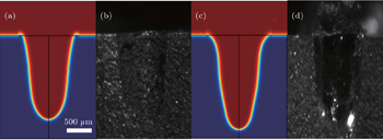
With the above proposed mathematical model, the laser drilling process can be reflected by numerical simulations. Firstly, cross-sections of keyhole for 304 stainless steel (304 SS) and aluminum, measured and calculated via both experiments and simulations, are shown in Fig. 2. In the experiments, The incident laser is a Nd:YAG long pulsed laser (Meyer-50, Beam-tech Optronics Co., Canada) with a wavelength of 1064 nm. The pulse width is set to be 1 ms. The focused radius is measured to be ∼ 260 μm via chlorine silver bromide paper. While in the simulation, the parameters are all based on the experimental conditions, such as the power density of laser pulse is 5.71 MW/cm2, the laser pulse width is 1 ms, and the focus radius is 260 μm. While the parameters of 304 SS and aluminum are listed in Table 1.

Fig. 2. Cross-sections of keyhole for simulation and experiment results on 304 SS and aluminum targets in laser drilling. (a) Simulation result of laser drilling on 304 SS; (b) experimental result of laser drilling on 304 SS; (c) simulation result of laser drilling on aluminum; (d) experimental result of laser drilling on aluminum. Laser pulse power density is 5.71 MW/cm2 and pulse width is 1 ms.
Table 1.

Physical properties of 304 SS and aluminum used in the simulation.[25,4446]

.

Figure 2 obviously shows the simulated keyhole structures fit well to the experimental results. The depth of the 304 SS keyhole is around 1.37 mm, which is close to 1.34 mm in simulation, besides, the equivalent diameter of the 304 SS keyhole is 0.75 mm, in simulation, while in experiment its value is 0.76 mm. In the case of aluminum, the depth and equivalent diameter are 1.48 mm and 0.68 mm in experiment, while 1.45 mm and 0.70 mm in simulation. The coincidences of keyhole shape and dimension between experiment and simulation indicate that the improved laser drilling model can well describe the real laser-material interaction.

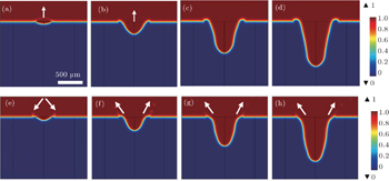
Then, applying the verified simulation model, the melt ejection can be well studied in rather high spatial and temporal resolution. Figure 3 shows the phenomena of melt ejection in both 304 SS and aluminum generated by a single laser pulse with a power density of 5.71 MW/cm2 and pulse width of 1 ms. In the case of 304 SS, melt ejection occurs only at an early stage (see Figs. 3(a) and 3(b)) of the drilling process and is perpendicular to the target; however, in subsequent stages, no obvious melt ejection happens as shown in Figs. 3(c) and 3(d). While in aluminum, an acute jet exists in the whole process (see Figs. 3(e) and 3(f)) and is inclining to the target. It means that there is a small quantity of molten material removed from the 304 SS keyhole, while for aluminum, there is a larger quantity of molten material in the keyhole to remove and it is easier for spatter to accumulate at the periphery of the keyhole in the ejection process.

Fig. 3. Phenomena of melt ejection at moments of: 235 μs ((a), (e)), 470 μs ((b), (f)), 704 μs ((c), (g)), and 939 μs ((d), (h)); for 304 SS ((a)–(d)) and aluminum ((e)–(h)) under 5.71 MW/cm2 laser power density irradiation and 1 ms pulse duration.

Figure 4 shows velocity field distributions of molten pools obtained from calculations. In the case of the aluminum, the whirlpool shaped flow in Fig. 4(e) illustrates that the fluid flow in the molten pool is intense and the ejection speed of material (metallic vapour and molten liquid) is much larger than that of the 304 SS target. The fluid in Fig. 4(e) also directly reveals that for aluminum, a certain quantity of molten material overflows out of the melt pool at the initial stage. Then, the fluid flows in Figs. 4(f)4(h) also reveal that at a later stage of the drilling process, a larger quantity of molten material flows up along the “green channel” by the effects of the temperature gradient of surface tension (Marangoni force) and recoil pressure.[47] When the recoil pressure of metallic vapour overcomes the surface tension of the molten liquid, the molten liquid is prone to break, detach and be ejected as can be seen in Figs. 3(f)3(h).[48]

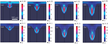
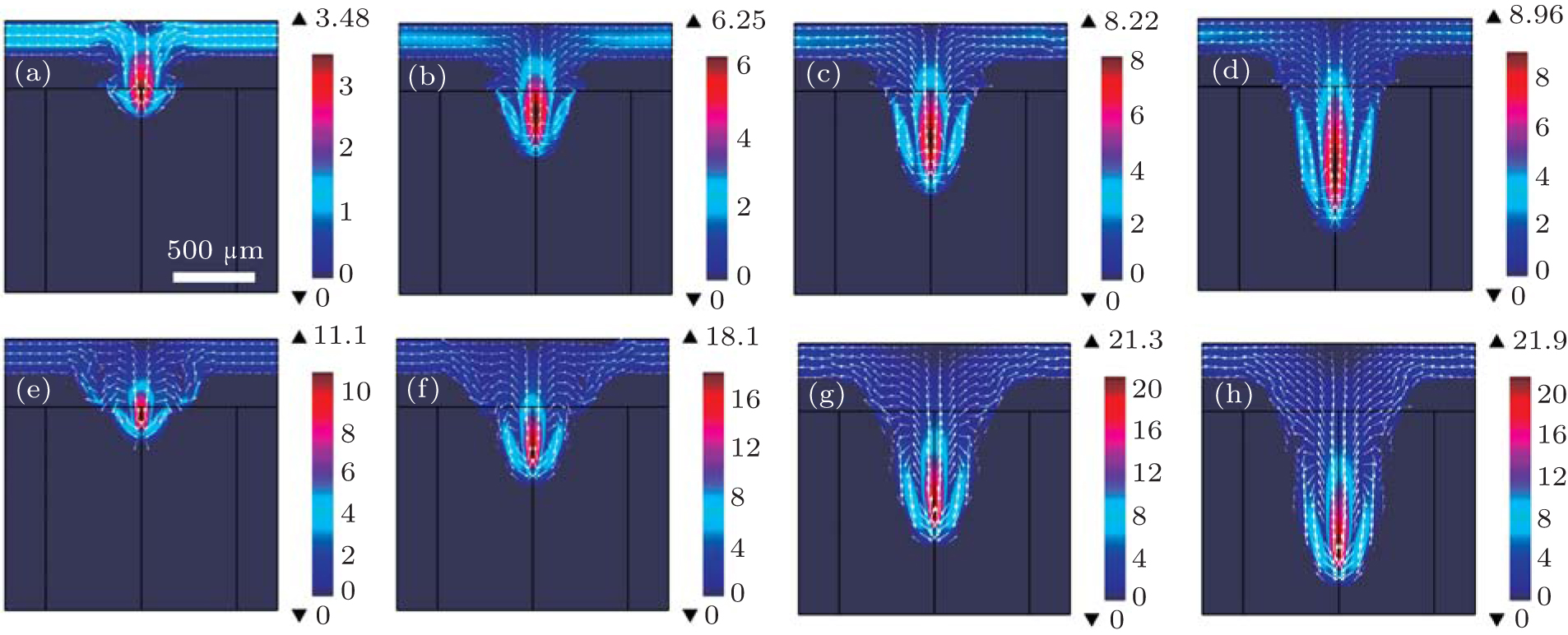
Fig. 4. Velocity field distributions of molten pool at moments of: 235 μs ((a), (e)), 470 μs ((b), (f)), 704 μs ((c), (g)), 939 μs ((d), (h)) for 304 SS ((a)–(d)) and aluminum ((e)–(h)) under 5.71 MW/cm2 laser power density irradiation and 1 ms pulse duration. The white arrows indicate the material flowing directions. The unit of the color bar is m/s.

It is worth noting that the ejection speed is not the decisive factor for the quantity of ejected liquid but the thickness of the liquid zone (molten layer) around the keyhole wall is. In order to quantitatively analyze this key point, temperature distributions of 304 SS and aluminum in the drilling process are also obtained in Fig. 5. As can be seen in Fig. 5, the heat affected zone increases with the evolution of laser-matter interaction for both materials, however, the temperature gradient across the keyhole wall for 304 SS is obviously large; these could mean that the liquid zone of 304 SS is smaller than that of aluminum. In order to have an insight into the temperature distribution, the temperature plots of both 304 SS and aluminum at free surface are shown in Fig. 6. According to melting temperatures and keyhole structures of metals, the thickness values of liquid zones are obtained, and show that the liquid zone thickness of aluminum is much larger than that of 304 SS, which are in agreement with the experimental results in Figs. 2(b) and 2(d); this is the reason why a large quantity of molten material is generated in the keyhole and a huge spatter is observed in aluminum targets (Figs. 3(e)3(h)).

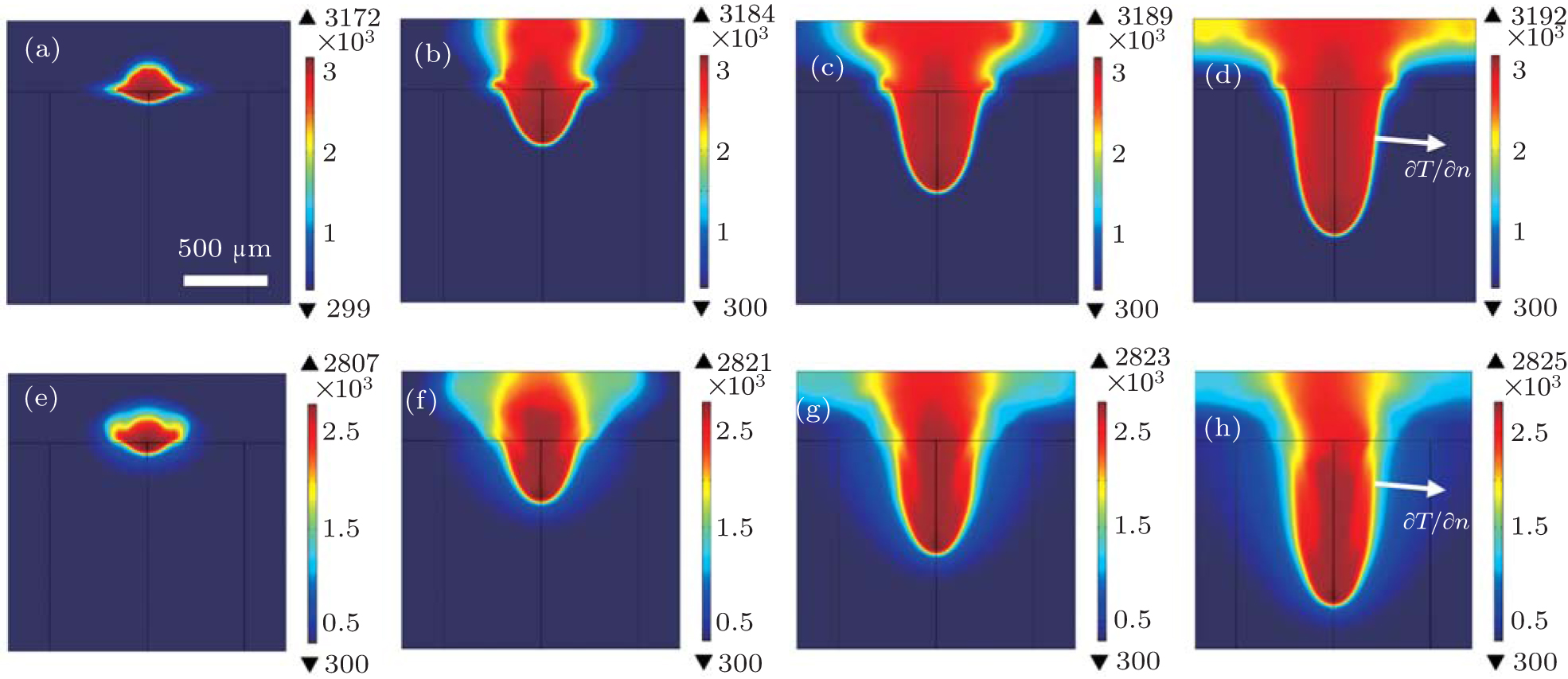
Fig. 5. Temperature field distributions of molten pool at moments of: 235 μs ((a), (e)), 470 μs ((b), (f)), 704 μs ((c), (g)), 939 μs ((d), (h)) for 304 SS ((a)–(d)) and aluminum ((e)–(h)) under 5.71 MW/cm2 laser power density irradiation and 1-ms pulse duration. The unit of the color bar is K.

The analysis indicates that the difference in liquid zone thickness is mainly caused by thermal diffusivity α which depends on density ρ, specific heat Cp, and thermal conductivity λ, and is given as follows:

According to Eq. (18), the thermal diffusivity values of 304 SS and aluminum are 4.46 × 10⁻⁶ m2/s and 1.09 × 10−4 m2/s, respectively. The thermal diffusivity of aluminum is 24 times higher than that of 304 SS, which indicates thermal dissipation in aluminum is much faster than that in 304 SS. Much more heat dissipates from the laser focal spot to the keyhole periphery and matrix at the same time, and a thicker liquid zone (because of the smaller temperature gradient) is generated across the keyhole wall for aluminum. Especially as shown in Fig. 6, the thickness of the liquid zone is nearly 320 μm and these molten materials mainly contribute to melt ejection in the laser drilling process. However, for 304 SS, it is only 50 μm, that is why there is so little melt ejection in the laser material interaction process as seen in Fig. 3.

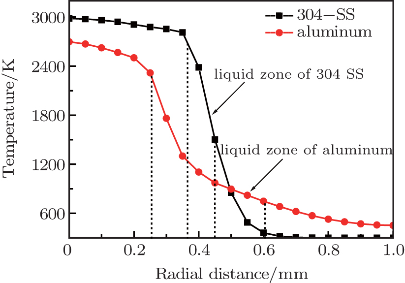
Fig. 6. Temperature plots of 304 SS (black solid squares) and aluminum (red solid circles) along the radical direction, with the original point corresponding to the center of the laser focal spot in simulation.

In this section, by using the improved mathematical model, the laser drilling process, especially the melt ejection phenomenon, is studied via numerical simulations. Utilizing the calculated flow and temperature field of the keyhole, the relation between the quantity of liquid ejection and material thermal diffusivity is deduced and the conclusions are obtained. Metal material with high thermal diffusivity such as aluminum has a small temperature gradient and thick liquid zone across the keyhole wall, and it is more prone to having a bigger quantity of melt ejection in the laser drilling process. In the following section, experimental observations and measurements are used to verify the conclusions obtained in numerical simulations and analysis.

4. Experiments

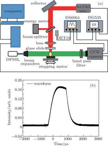
To verify the numerical simulation and the relation between melt ejection and thermal diffusivity, experiments are conducted for direct observation and measurements. The quasi-real time observations of laser drilling are realized by the shadowgraphic technique. The experimental setup is shown in Fig. 7(a): a Nd:YAG long pulsed laser (Meyer-50, Beam-tech Optronics Co., Canada) is used as a heat source for laser drilling. Its wavelength is 1064 nm and the output laser owns a beam divergence angle of less than 3 mrad. The laser pulse width can be set to be in a range between 0.5 ms and 2.5 ms, besides, the maximal output laser energy is 50 J. In the experiment, laser pulse width is selected to be 1 ms (Fig. 7(b)), which meets the requirement of numerical simulations. In addition, the output laser energy is 12.1 J, with a focusing lens (focal length 18.5 mm) set to be above the metal targets, and the power density can reach 5.71 MW/cm2. Moreover, the TEM00 mode is used in laser drilling. Another continuous semiconductor laser (DPSSL) with 50 mW power and 532 nm wavelength coupling with beam expanders with an expansion factor of 8 is used for illumination. A high speed charge-coupled-device CCD camera (Gigaview, Southern Vision Systems Inc., USA) is used to capture the “shadow” images of spatter during laser drilling. In the experiment, the capturing frame rate is 4261 fps at a pixel resolution of 1280 × 128. Besides, a band-pass filter (λ = 532 nm, and full width half maximum (FWHM) = 10 nm) is used. The metal targets are fixed on the three-dimensional (3D) precision translation stage (Beijing Optical Century Instrument Co., Ltd. China) for spatial adjustment. A combination of beam-splitter and energy meter (Beijing Institute of Opto–Electronic Technology, China) is used in the system to measure the laser energy. A four-channel digital delay system (DG535, Stanford Research Systems, USA) is used to trigger the long pulsed laser for laser drilling, a digital oscilloscope ((DS6064, RIGOL Technologies Inc., China,) is used to show the signal delay between the laser pulse and CCD, and high speed CCD camera, which is connected to the PC directly through the USB interface for control and information storage, is used for capturing the images to record the phenomena of material ejection in real time. Besides, a glass slide is placed perpendicularly to the light path about 10 mm away from the target front surface for collecting molten material and shift after each drilling, each energy density is tested 20 times and many an energy density is conducted. Finally, an electronic scale (AL2024, Mettler Toledo Co. Ltd., Shanghai) with an accuracy of 0.0001 g is adopted to measure the mass of the collected molten material and variation of target mass.

Fig. 7. (a) Schematic of real time laser drilling observation via the shadowgraphic technique, and (b) the laser pulse waveform with an FWHM of τ being 1 000 μs.

The shadowgraphs of melt ejection for both 304 SS and aluminum, captured by the real time laser drilling observation system, are shown in Figs. 8(a)8(d) and Figs. 8(e)8(h), respectively. As indicated by the red arrows in Fig. 8, the melt ejection in aluminum is much more obvious than that in 304 SS, the results in experiment fit well to the conclusions in simulation. Moreover, the melt ejection fractions (collected melt mass versus measured mass change of substrate) of about 37% for 304 SS and 65% for aluminum coincide with the data in the literature,[49] which means that melt ejection is a primary drilling mechanism for material removal for aluminum. Finally, the keyhole surface morphologies for both materials after laser drilling in the same condition are shown in Fig. 9. It is clear that the periphery of the keyhole surface of aluminum has a larger quantity of depositions than that of 304 SS as the accumulated depositions are mostly generated by molten ejection during laser drilling. Therefore, it also certifies that melt ejection often occurs in high thermal diffusivity materials like aluminum rather than in low thermal diffusivity materials such as 304 SS, which accords well with the conclusions obtained in the above mentioned numerical simulations and analysis.

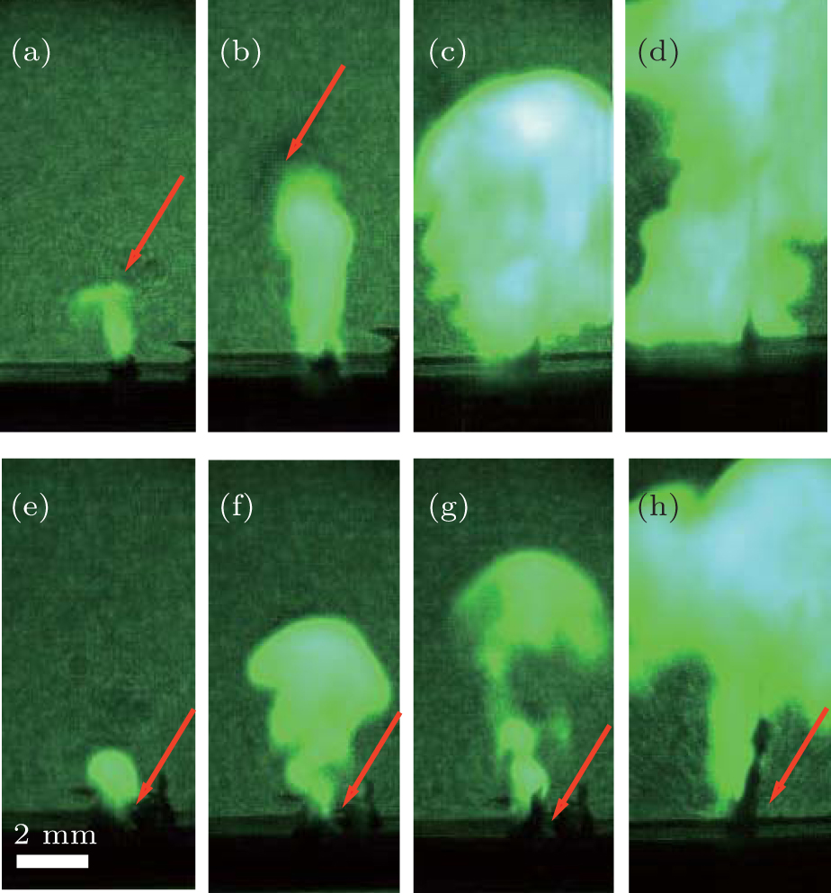
Fig. 8. Shadowgraphs and emitted light images for material removal (vapour jet and melt ejection) at moments of 235 μs ((a), (e)), 470 μs ((b), (f)), 704 μs ((c), (g)) and 939 μs ((d), (h)) for 304 SS ((a)–(d)) and aluminum ((e)–(f)) under a laser power density of 5.71 MW/cm2 irradiation and laser pulse width of 1 ms. The red arrows indicate the melt ejection.
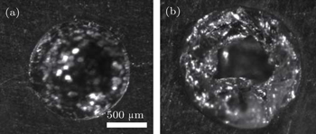
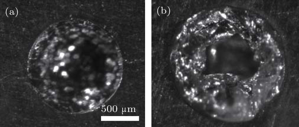
Fig. 9. Optical microscope images of a drilled hole showing material removal from the hole in the melt phase for (a) 304 SS and (b) aluminum. Drilling conditions are the same as those in Fig. 8.

From this experimental observation and analysis it follows that the melt ejection control is of great importance in keyhole manufacturing (for different materials with widely different thermal properties): it is a significant process in keyhole formation during laser drilling, besides, the spatter is also an important factor for burr, dross and hump formation along the keyhole periphery. Since the surface quality is as important as the formed keyhole structure, understanding the melt ejection in laser drilling is useful for keyhole fabrication and surface quality control.

5. Conclusions

In order to understand the mechanisms of melt ejection in laser drilling in detail, in this paper, both simulations and experiments are carried out to study the influences of material parameters on melt ejection in laser drilling on 304 SS and aluminum targets. With an improved mathematical model, the result shows that melt ejection is influenced not only by the forces acting on the free surface and fluid flow in the melt pool, but also by the liquid zone (molten layer) across the keyhole wall. According to heat transfer theory, the thickness of the liquid zone is mainly determined by the thermal diffusivity of material. For high thermal diffusivity material like aluminum, a small temperature gradient occurs in the solid target, and a thick liquid zone will be generated across the keyhole wall. These molten metals mainly contribute to melt ejection. Finally, experimental measurements for both 304 SS and aluminum verify the accuracy of the mathematical model and the quantitative analysis for melt ejection. Additionally, the conclusions presented in this paper can be applied to other metals such as copper, nickel based alloys and titanium, etc.

With both proposed numerical simulations and experimental observations, the quasi-quantitative relation between melt ejection and thermal diffusivity is established: materials with high thermal diffusivity, such as aluminum, small temperature gradient and thick liquid zone across the keyhole wall, easily generate a large quantity of melt ejection in a long pulsed laser drilling process. The research in this paper will serve as a guidance for manufacturing optimization and quality control in laser drilling.

Reference
1Yang X DXu Z ZLeng Y XLu H HLin L HZhang Z QLi R XZhang W QYin D JTang B 2002 Opt. Lett. 27 1135
2An RLi YDou Y PFang YYang HGong Q H 2004 Chin. Phys. Lett. 21 2465
3Wang JWang H PLu F GCarlson B ESigler D R 2015 Int. J. Heat Mass Transfer 89 1061
4Liu YZhu H NPei Z DKong Y FXu J J 2015 Chin. Phys. 24 056802
5Pan DHuang Z CHuang J KWang X XHuang Y 2015 Acta Phys. Sin. 64 108102 (in Chinese)
6Voisey K TClyne T W 2004 Surf. Coat. Technol. 176 296
7Duan W QWang K DDong XMei X SWang W JFan Z J 2015 Int. J. Adv. Manu. Technol. 76 1529
8Allmen M V 1976 J. Appl. Phys. 47 5460
9Berrie P GBirkett F N 1980 Opt. Laser. Eng. 1 107
10Low D K YLi LByrd P J 2003 J. Mater. Process. Technol. 139 71
11Low D K YLi L 2001 Opt. Laser Technol. 33 515
12Low D K YLi LByrd P J 2000 Opt. Laser Technol. 32 347
13Voisey K TKudesia S SRodden W S OHand D PJones J D CClyne T W 2003 Mat. Sci. Eng. 356 414
14Trippe LWillach JKreutz E WSchulz WPetereit JKaierle SPoprawe R2004Fifth International Symposium on Laser Precision MicrofabricationMay 11–14, 2004Nara, Japan609615609–15
15Chen MWang YYu GLan DZheng Z Y 2013 Appl. Phys. Lett. 103 194102
16Zhang YLi S CChen G YMazumder J 2013 Opt. Laser Technol. 48 405
17Low D K YLi LByrd P J 2002 J. Manuf. Sci. E-T ASME 124 852
18Song L SShi G QLi Z G2006Acta Armamentarii27879
19Muhammad NRogers B DLi L 2013 J. Phys. D: Appl. Phys. 46 095101
20Solana PKapadia PDowden JRodden W S OKudesia S SHand D PJones J D C 2001 Opt. Commun. 191 97
21Shen Z HZhang S YLu JNi X W 2001 Opt. Laser Technol. 33 533
22Yang L XPeng X FWang B X 2001 Int. J. Heat Mass Transfer 44 4465
23Xu B QShen Z HLu JNi X WZhang S Y 2003 Int. J. Heat Mass Transfer. 46 4963
24Zang Y NNi X WHan B 2014 J. Appl. Phys. 116 013104
25Zhang Y MShen Z HNi X W 2014 Int. J. Heat Mass Transfer 73 429
26Zhang T ZNi X WLu J 2015 Chin. Opt. Lett. 13 081403
27Bandyopadhyay SSundar J K SSundararajan GJoshi S V 2002 J. Mater. Process. Technol. 127 83
28Hugger FHofmann KKohl SDobler MSchmidt M 2015 Weld Word 59 165
29Samant A NDui B SPaital S RKumar SDahotre N B 2009 J. Mater. Process. Technol. 209 5060
30He X LSong L JYu GMazumder J 2011 Appl. Surf. Sci. 258 898
31Hao M ZSun Y W 2013 Int. J. Heat Mass Transfer 64 352
32Quintero FVaras FPou JLusquinos FBoutinguiza MSoto RAmor M P 2005 J. Phys. D: Appl. Phys. 38 655
33Wang X JWang H PLu F GCarlson B EWu Y X 2014 Int. J. Adv. Manuf. Technol. 73 73
34Pang S YChen XZhou J XShao X YWang C M 2015 Opt. Laser. Eng. 74 47
35Sussman MSmereka POsher S 1994 J. Comput. Phys. 114 146
36Ki HMohanty P SMazumder J 2001 J. Phys. D: Appl. Phys. 34 364
37Pang S YChen L LZhou J XYin Y JChen T 2011 J. Phys. D: Appl. Phys. 44 025301
38Li T QWu C SFeng Y HZheng L C 2012 Int. J. Heat Fluid Fl. 34 117
39Tan WBailey N SShin Y C 2013 J. Phys. D: Appl. Phys. 46 055501
40Courtois MCarin MMasson P LGaied SBalabane M 2014 J. Laser Appl. 26 042001
41Hirano KFabbro RMuller M 2011 J. Phys. D: Appl. Phys. 44 435402
42Allmen M V1987Laser-beam Interactions with MaterialsBerlinSpringer163165163–5
43Vora H DSanthanakrishnan SHarimkar S PBoetcher S K SDahotre N B 2012 J. Eur. Ceram. Soc. 32 4205
44Rai RElmer J WPalmer T ADebRoy T 2007 J. Phys. D: Appl. Phys. 40 5753
45Wang R PLei Y PShi Y W 2011 Opt. Laser Technol. 43 870
46Tunna LONeill WKhan ASutcliffe C 2005 Opt. Laser. Eng. 43 937
47Ng G K LCrouse P LLi L 2006 Int. J. Heat Mass Transfer 49 1358
48Riveiro AQuintero FLusquinos FComesana RPou J 2011 J. Phys. D: Appl. Phys. 44 135501
49Voisey K TCheng C FClyne T W2000Mat. Res. Soc. Symp. Proc.CambridgeCambridge University PressJ56J5–6