Graphene/polyaniline composite sponge of three-dimensional porous network structure as supercapacitor electrode
Jiang Jiu-Xing, Zhang Xu-Zhi, Wang Zhen-Hua†, , Xu Jian-Jun
School of Applied Science, Harbin University of Science and Technology, Harbin 150080, China


† Corresponding author. E-mail: wzhua@hrbust.edu.cn

Project supported by the Natural Science Foundation from Harbin University of Science and Technology and Harbin Institute of Technology.

Abstract
Abstract

As a supercapacitor electrode, the graphene/polyaniline (PANI) composite sponge with a three-dimensional (3D) porous network structure is synthesized by a simple three-step method. The three steps include an in situ polymerization, freeze-drying and reduction by hydrazine vapor. The prepared sponge has a large specific surface area and porous network structure, so it is in favor of spreading the electrolyte ion and increasing the charge transfer efficiency of the system. The process of preparation is simple, easy to operate and low cost. The composite sponge shows better electrochemical performance than the pure individual graphene sponge while PANI cannot keep the shape of a sponge. Such a composite sponge exhibits specific capacitances of 487 F·g−1 at 2 mV/s compared to pristine PANI of 397 F·g−1.

1. Introduction

As a single layer of carbon atoms, graphene which was discovered in 2004 by Novoselov et al.[1,2] exhibits extraordinary electrical, thermal and mechanical properties.[3] Graphene sponge which has a three-dimensional (3D) porous network structure has a large specific surface area and a fast electron transportation, so it can be used as a supercapacitor electrode. Because of the compressibility of sponge, it can also be used for other purposes, such as the compressible supercapacitor and sensor, etc. However, the pure individual graphene sponge has unsatisfactory capacitance.[4] Nowadays, graphene/polyaniline (PANI) has been successfully considered to be one of the most promising electrode materials due to its easy synthesis and relatively high conductivity and lower cost than many other conducting polymers.[5,6] However, swelling and shrinkage of PANI will occur in the process of doping/de-doping. Such a behavior may result in mechanical degradation of the electrode and fading of the electrochemical performance, so PANI reveals the disadvantage of a low cycle life.[7,8] The combination of PANI with various porous carbon materials will not only reinforce the stability of PANI, but also maximize the capacitance value.[6] Moreover, due to the large specific surface area, graphene has been proved to be an attractive substrate material when compounded with polymers and inorganic particles for lithium ion batteries, electrochemical capacitors or in other fields.[911] Graphene can create a local electrically conducting network to improve the specific capacitance and electrochemical cyclic stability of the electrode.[12,13] Therefore, the incorporation of graphene is highly favorable to synthesize nanoscale PANI. However, there is still a great challenge to the full use of the large surface area of graphene layers. The problem is that graphene may easily form irreversible agglomerates through van der Waals interactions.[14] By contrast, the oxygen-containing functional groups of GO facilitates stable dispersion in aqueous medium, in this case, it is easy to form a multilayer nanostructure of GO in solution.[12,15] Most researches show that the solution of graphene/PANI material was dried by a vacuum drying method, which only obtains powder or flake of the material.[6,9,14]

Herein, we report a simple three-step method to form the graphene/PANI composite sponge of 3D porous network structure. The composite sponge of graphene/PANI can macroscopically be seen as bulk, which is different from powder or flake, and microscopically, the composite sponge is of a 3D porous network structure. The 3D porous network structure is in favor of spreading the electrolyte ion and increasing the charge transfer efficiency of the system. Well dispersed deposition of PANI nanosheets on GO sheet could effectively increase the electrochemical utilization of PANI, and reduce the ion diffusion path during, that is, charge–discharge.[12] As a result, such a composite sponge exhibits better specific capacitance and cycling stability than pure graphene or PANI.

2. Experiment
2.1. Material preparation
2.1.1. Preparation of graphene oxide (GO)

GO was synthesized from natural graphite by a modified Hummers method.[16] Firstly, graphite was turned into the expanded graphite by the method of acidification, drying and heating of a furnace tube. Then the expanded graphite was added into a 50-°C solution of concentrated H2SO4, concentrated H3PO4 and KMnO4, and the mixture was allowed to react for 6 h. After that, the reaction mixture was added into an ice water mixture and then stirred. In the final procedure, the mixture was treated with 30%-H2O2 until the color of the mixture became bright yellow to obtain a graphite oxide suspension. Finally the graphite oxide suspension was washed with 1:10 HCL solution and distilled water and centrifuged to obtain graphene oxide having a density of 8 mg/ml. The GO dispersion was centrifuged and the precipitate was directly dispersed in the solvent for the experimental step.

2.1.2. Preparation of the composite sponge of GO/PANI

Exfoliation and dispersion of GO (200 mg) in 200 mL of distilled water were achieved by ultrasonication in an ultrasonic bath for 1 h. After that, aniline monomers (solvent: 1-M HCL) were added into the above suspension and sonicated for a moment. Afterwards, ammonium persulfate (APS, solvent: 1-M HCL) were rapidly added into the above mixture and stirred for 6 h in ice water mixture; the yellow–brown suspension gradually changed into a deep green color. Then the reactant was placed in a beaker and freeze-dried to obtain the composite sponge of GO/PANI. In this process, the molar ratio of aniline monomers to APS was 1:2 while the mass ratio of GO to aniline monomers was 1:0.4,1:1,1:3,1:5, etc. The composite sponge of GO/PANI was expressed as GOP, so the as-prepared products were named GOP1:0.4, GOP1:1, GOP1:3, GOP1:5. For comparison, the pure PANI and GO were also synthesized using a similar procedure to the above. The concentration of GO of all the composite GO/PANI material was 3 mg/ml.

2.1.3. Preparation of the composite sponge of Graphene/PANI

The composite sponge of Graphene/PANI was obtained by reducing the prepared composite sponge of GO/PANI (from 2.1.2) in the steam environment of hydrazine at about 90 °C for 1 h. The composite sponge of graphene/PANI was expressed as RGP.

2.2. Characterization

Scanning electron microscope (SEM) and infrared spectrum (FT-IR) equipment were used to characterize the textures, morphologies and chemical structures of GO, PANI, GOP and RGP. The SEM sample was prepared by using conductive adhesive pasting the sample onto a conductive copper plate. FT-IR spectra of films of GO, PANI, GOP, and RGP were recorded by a BRUKER TENSOR 27 FT-IR spectrometer with a smart OMNI sampler with potassium bromide crystal. X-ray photoelectron spectrum (XPS) measurement was performed using monochromator Al Kα irradiation. As suggested in the literature,[17] the electrochemical properties of the composite sponge of Graphene/PANI were characterized using a PARSTAT 4000 electrochemical working station with a three-electrode system in 2-M H2SO4 electrolyte at room temperature. The composite sponge of graphene/PANI served as the working electrode, while a platinum wire and an Ag/AgCl electrode were used as the counter electrode and the reference, respectively. The potential range for cyclic voltammetry (CV) measurements was from 0 V to 0.8 V at a scan rate of 2 mV·s−1.

3. Results and discussion
3.1. Morphology and structure

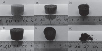
The macroscopic appearance of all the samples except PANI (in Fig. 1) prepared by freeze-drying are sponge-like. The color deepens until it becomes dark green from brown with the increase of the content of PANI. However, PANI becomes loose powder and bulk, and overall is shapeless. After the addition of GO, the composite material can be shaped and GO forms the frame while PANI is adsorbed on the surface of GO.

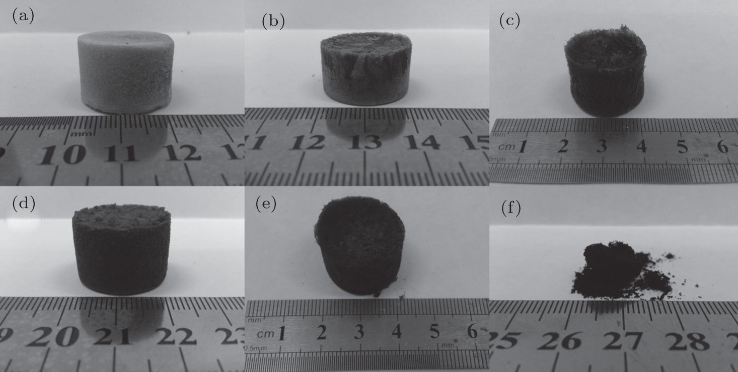
Fig. 1. Optical images of (a) sponge of GO, composite sponge of (b) GOP1:0.4, (c) GOP1:1, (d) GOP1:3, (e) GOP1:5, and (f) PANI power prepared by the process of freeze drying.
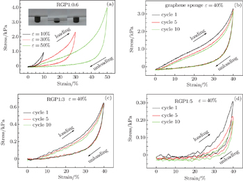
As shown in Fig. 2(a), the compressive stress–strain curve of RGP1:0.6 shows strains of 10%, 30%, and 50% of three different stages respectively. It can be seen that the stress increases linearly at ɛ < 10%, gently at 10% < ɛ < 40%, and rapidly at ɛ > 40%. Cyclic tests are also conducted in Figs. 2(b)2(d). With the increase of the number of cycles of compression, the compressive curve shifts to the right, indicating that the plastic deformation increases but gradually becomes stabilized. Experiments show that the plastic deformation of the 10th compressive curve of graphene sponge or RGP1:0.6 is almost zero at ɛ = 40% compared with that of the first one, indicating that the sponge can restore elasticity completely. However, the plastic deformations of RGP1:3 and RGP1:5 are respectively 1.7% and 5.5%. In summary, the composite sponge prepared by freeze-drying has a certain compressibility, and the compressible performance decreases with the content of PANI increasing.

Fig. 2. Compressive stress–strain curves of RGP1:0.6 (a), the stress–strain curves of graphene sponge (b), RGP1:3 (c), and RGP1:5 (d) at a maximum strain of 40% for 10 cycles.
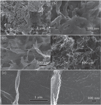
As shown in Figs. 3(a) and 3(b), pure PANI forms a porous structure but seriously aggregates. Most of PANIs are disorderly entangled and gather together. As shown in Fig. 3(c), the sponge of GO obtained by the freeze-drying process supplies a porous network structure. GO/PANI sponge (Fig. 3(d)) also shows a porous network structure, but the sizes of pores are reduced compared with those of the GO sponge. This is because PANI adhered to the surface of GO after the reaction between GO and PANI, resulting in the decrease of the pore diameter of composite sponge. However, the decreasing of the micron-size is more conducive to the increasing of the specific surface area.[18] The porous network structure will not only help to improve the specific surface area of the composite material, but also be conducive to the further spreading of the electrolyte ions. As can be seen in Figs. 3(e) and 3(f), PANI is coated evenly on the surface of graphene in the graphene/PANI sponge without obvious agglomeration, so the reunion extent is weaker than in the pure PANI. Good dispersion of PANI electrode material is beneficial to the increase of the specific surface area, facilitates the ion moving to the inner part, thus improving the utilization of pseudocapacitance of PANI.[12,19]

Fig. 3. SEM images of ((a) and (b)) pure PANI at different magnifications. Both of them show the aggregations of nanofibers and nanoparticles mixture; SEM images of (c) GO, (d) GO/PANI. Each of them shows a 3D porous network structure; SEM images of ((e) and (f)) graphene/PANI at different magnifications. Each of them shows that graphene is evenly coated by PANI.

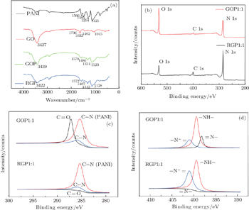
In the FT-IR spectrum of GO (Fig. 4(a)), the peaks around 3427, 1736, and 1402 cm−1–1045 cm−1 are attributed to the O–H, C=O in COOH, and C–O in C–OH/C–O–C functional groups, respectively.[20] As for PANI based hybrid materials, the new peaks at 1566, 1485, 1294, and 1121 cm−1 are attributed to the vibration of C=C stretching of the quinoid rings, C=C stretching of benzene rings, C–N stretching mode, and N=Q=N (Q denotes quinoid ring).[21,22] Notably, the reduced peak of O–H and disappeared peak of C=O for PANI based hybrid material are clearly observed, indicating that those groups act as the nucleation sites that link with the nitrogen of PANI backbone for producing PANI nanosheets.[23] Figure 4(b) shows the XPS results of GOP and RGP. The O/C ratio decreases from 0.954 in GOP to 0.368 in RGP after the treatment by hydrazine vapor. The reduced oxygen content increases the sp2 carbons on the graphene sheets, leading to the increase of the ππ interaction between graphene and PANI chain.[9] This may facilitate the electron transfer and bring a synergistic effect on the electrochemical properties of the composite sponge. Notably, a peak located at 287.20 eV[24,25] in Fig. 4(c) is exhibited, which is attributed to the C=O bond. After GOP is reduced by hydrazine vapor, the peak density is significantly weakened. This further indicates that the oxygen-containing functional groups of RGP are less than GOP, so RGP is more conducive to electron transfer. The peak located at 285.35[25] corresponding to the C–N bond describes the existence of PANI and the formation of part of amide bonds is confirmed by the C–N bond around 285.8.[2527] Figure 4(d) exhibits the peaks of 398.2 and 399.4,[28] which represent the quinone-amine (=N–) and benzene-amine (–NH–). It can be seen that hydrazine vapor has some influence on the structure of PANI by contrasting RGP with GOP. And the increasing of nitrogen cation radical (–N + =) at around 401 eV in RGP indicates that the doping case of RGP is better than GOP.[24] In summary, the oxygen-containing functional groups of RGP do become less after GOP has been reduced and the decreasing of oxygen-containing functional groups may facilitate the electron transfer and improve specific capacitance.

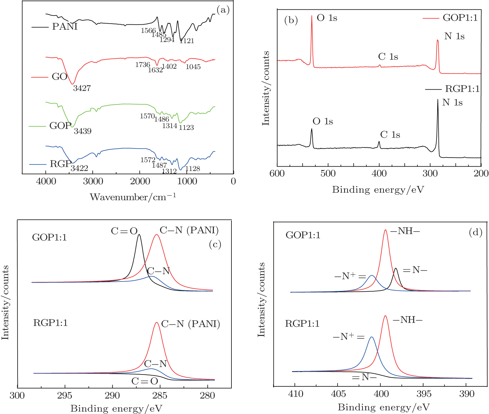
Fig. 4. FT-IR (a) and XPS spectrum of GOP and RGP. (b) Elements in the spectrum. (c) C 1s core level spectrum of GOP and RGP. (d) N 1s core level spectrum of GOP and RGP.
3.2. Supercapacitor characterizations

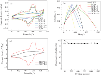
As is well known, the PANI deposited on carbon nanomaterials is found to be particularly advantageous to the supercapacitor because carbon material can provide a high surface area and excellent conductivity. This results in the deposition of nanostructured material with high specific capacitance.[29] The electrochemical performances of graphene/PANI materials as supercapacitor electrodes are investigated by using cyclic voltammetry (CV) and galvanostatic charge–discharge (GCD). Figure 5(a) shows the CV curves of the pristine PANI, RGP1:5, RGP1:3, RGP1:1, RGP1:0.6, RGP1:0.4, and RGO at a scan rate of 2 mV·s−1 in 2-M H2SO4 electrolyte in a potential range from 0 V to 0.8 V.[30] Their specific capacitances are 397 F·g−1, 487 F·g−1, 448 F·g−1, 228 F·g−1, 205 F·g−1, 189 F·g−1, and 162 F·g−1. The CV curves of RGP1:5 and RGP1:3 show a larger rectangular area than that of RGO, which indicates that the capacitance performances of RGP1:5 and RGP1:3 are better than that of RGO as shown in Fig. 5(a). The specific capacitances of RGP1:5 and RGP1:3 are 3 times and 2.8 times larger than that of RGO, respectively. However, the areas of the CV curve of RGP1:1, RGP1:0.6, and RGP1:0.4 are slightly larger than that of RGO, revealing their lower capacitance property than those of RGP1:5 and RGP1:3. Meanwhile it could be attributed to the poor conductivity of a high amount of graphene which is incompletely extirpated.[17] The specific capacitances of RGP1:1, RGP1:0.6 and RGP1:0.4 are 1.4, 1.3, and 1.2 times larger than that of RGO, respectively. The same situation can also be seen in Fig. 5(b). Therefore, combining the visible shape and strength of composite sponge mentioned above, graphene plays a decisive role in the structure of sponge but not in the capacitor. By contrast, PANI plays a leading role in the capacitor in the composite sponge of graphene and PANI, namely pseudo-capacitive promotes the upgrading of the overall capacitance. The porous network structure of composite sponge from the polymerization of graphene and PANI exhibits a high capacitance property and synergistic effect.[26,28] The porous network structure increases the specific surface area and is favorable for the diffusion of ion, thus accelerating the transport rate of ion and improving the specific capacitance.[18,31,32] The synergistic effect can be explained as follows. The staggered aggregation between graphene and PANI effectively hinders the agglomeration of PANI which is conducive to the transport of ions and electrons in the processes of charge and discharge, thereby increasing the specific capacitance of the composite material. The porous network structure of composite sponge formed by adding the graphene not only is beneficial to the inflow and infiltration of electrolyte ions, but also can alleviate the expansion and contraction of PANI in the repeated charge-discharge process and improve the stability of a cycle.[33,34] Both and infiltration of electrolyte ions, but also can alleviate the expansion and contraction of PANI in the repeated charge-discharge process and improve the stability of cycle.[33,34] Both graphene and PANI effectively play their respective strength and synergist effect, and this method increases the electrochemical properties of composite materials. As shown in Fig. 5(a), both PANI and the composite electrodes show a pair of redox peaks. The specific capacitance of PANI based hybrid material mainly originates from pseudo-capacitance, unlike the electric double layer capacitance of carbon-based materials.[35] This is attributed to the fact that the composite undergoes a redox reaction between the reduction and oxidation state of PANI, which means that PANI is doped and de-doped in an acidic electrolyte.

Fig. 5. Electrochemical performances: (a) CV curves of PANI, RGP1:5, RGP1:3, RGP1:1, RGP1:0.6, RGP1:0.4, RGO, with the scan rate being 2 mV/s; (b) charge/discharge curves at a current density of 0.5 A/g; (c) CV curves of GOP1:5 and RGP1:5, with the scan rate is 2 mV/s; (d) cycling tests of 1000 charging and discharging cycles at 100 mV·s.

Notably, as shown in Fig. 5(c), the area enclosed by the CV curve of RGP1:5 is larger than that of GOP1:5, which indicates that the RGP1:5 exhibits better specific capacitance performance and that the reduction of GOP1:5 is effective in improving the specific capacitance. However, the area enclosed by the CV curve of GOP1:5 is much smaller than that of PANI, revealing a lower specific capacitance, and it may be attributed to the high amount of GO with poor conductivity.[16] Finally, figure 5(d) shows the tested CV cycling stability of the electrode 1000 cycles at a scanning rate of 200 mV·s−1. It is found that the capacitance of the electrode maintains 89.4% after 1000 charging and discharging cycles, which suggests a good cycling stability of this grapheme/polyaniline composite sponge.

4. Conclusions

The 3D porous structure of the grapheme/polyaniline composite sponge is conducive to the diffusion of ion, and the surface of grapheme evenly coated with PANI exhibits short ion diffusion lengths, and good electrochemical utilization of PANI. Because of the compressibility of the sponge, it can also be used for other purposes, such as the compressible supercapacitor and sensors, etc. Of course, this also requires us to carry out further research. The electrochemical studies and SEM of composite sponge prove that graphene/PANI hybrid materials each possess a synergistic effect of PANI nanosheets and graphene. The composite sponge shows higher electrochemical capacitance, rate performance and cycling stability than each individual component. Therefore, the intriguing graphene/PANI composite sponge is quite a suitable and promising electrode material for supercapacitors.

Reference
1Luo W GWang H FCai K MHan W PTan P HHu P AWang K Y 2014 Chin. Phys. Lett. 31 67202
2Novoselov K SGeim A KMorozov S VJiang DZhang YDubonos S VGrigorieva I VFirsov A A 2004 Science 306 666
3Bunch J SVan der Zande A MVerbridge S SFrank I WTanenbaum D MParpia J MCraighead H GMcEuen P L 2007 Science 315 490
4Liu YDeng R JWang ZLiu H T 2012 J. Mater. Chem. 22 13619
5Wang Y GLi H QXia Y Y 2006 Adv. Mater. 18 2619
6Yan JWei TFan Z JQian W ZZhang M LShen X DWei F 2010 J. Power Sources 195 3041
7Fan L ZHu Y SMaier JAdelhelm PSmarsly BAntonietti M 2007 Adv. Funct. Mater. 17 3083
8Li L XSong H HZhang Q CYao J YChen X H 2009 J. Power Sources 187 268
9Wang H LHao Q LYang X JLu L DWang X 2010 Nanoscale 2 2164
10Yao JShen X PWang BLiu H KWang G X 2009 Electrochem. Commun. 11 1849
11Xu YWang YLiang JHuang YMa YWan XChen Y 2009 Nano Res. 2 343
12Ning G QLi T YYan JXu C G 2013 Carbon 54 241
13Wang H LHao Q LYang X JLu L DWang X 2010 ACS Appl. Mater. Inter. 2 821
14Yan X BChen J TYang JXue Q JMiele P 2010 ACS Appl. Mater. Inter. 2 521
15Compton O CDikin D APutz K WBrinson L CNguyen S T 2010 Adv. Mater. 22 892
16Daniela C MDmitry V KJacob M B 2010 ACS Nano. 8 4806
17Dong X CWang J XWang J 2012 Mater. Chem. Phys. 134 576
18Zhai Y PDou Y QZhao D YFulvio P F 2011 Adv. Mater. 23 4828
19Fei J BCui YYan X HYang YWang K WLi J B 2009 ACS Nano 3 3714
20Wang H LHao Q LYang X JLu L D 2009 Electrochem. Commun. 11 1158
21Acevedo D FRivarola C RMiras M CBarbero C A 2011 Electrochim. Acta 56 3468
22Rozlívková ZTrchová MExnerová M 2011 Synth. Met. 161 1122
23Laslau CZujovic ZTravas-Sejdic J 2010 Prog. Polym. Sci. 35 1403
24An J WLiu J HZhou Y CZhao H F2012J. Phys. Chem.11619699
25Ramanathan TFisher F TRuoff R SBrinson L C 2005 Chem. Mater. 17 1290
26Wu QXu Y XYao Z YLiu A RShi G Q 2010 ACS Nano 4 1963
27Lee Y MKim J HKang J SHa S Y 2000 Macromolecules 33 7431
28Zhang KZhang L LZhao X SWu J S 2010 Chem. Mater. 22 1392
29Wu TLin YLiao C 2005 Carbon 43 734
30Liu YMa YGuang S YXu H YSu X Y 2014 J. Mater. Chem. 2 813
31Arico A SBruce PScrosati BTarascon J MSchalkwijk W V 2005 Nat. Mater. 4 366
32Li CShi G Q 2012 Nanoscale 4 5549
33Li LSong HZhang QYao JChen X 2009 J. Power Sources 187 268
34Khomenko VFrackowiak EBéguin F 2005 Electrochim. Acta 50 2499
35Zhang L LZhao X S 2009 Chem. Soc. Rev. 38 2520