Channeling of fast ions through the bent carbon nanotubes: The extended two-fluid hydrodynamic model
Karbunar Lazar1, †, , Borka Duško2, ‡, , Radović Ivan2, §, , Mišković Zoran L3, ¶,
School of Electrical Engineering, University of Belgrade, Bulevar Kralja Aleksandra 73, 11120 Belgrade, Serbia
Vinča Institute of Nuclear Sciences, University of Belgrade, P. O. Box 522, 11001 Belgrade, Serbia
Department of Applied Mathematics and Waterloo Institute for Nanotechnology, University of Waterloo, Waterloo, Ontario, Canada N2L 3G1


† E-mail: ziloot@verat.net

‡ Corresponding author. E-mail: dusborka@vin.bg.ac.rs

§ E-mail: iradovic@vin.bg.ac.rs

¶ E-mail: zmiskovi@uwaterloo.ca

Project supported by the Funds from the Ministry of Education, Science and Technological Development of the Republic of Serbia (Grant No. 45005). Z. L. Mišković thanks the Natural Sciences and Engineering Research Council of Canada for Finacial Support.

Abstract
Abstract

We investigate the interactions of charged particles with straight and bent single-walled carbon nanotubes (SWNTs) under channeling conditions in the presence of dynamic polarization of the valence electrons in carbon. This polarization is described by a cylindrical, two-fluid hydrodynamic model with the parameters taken from the recent modelling of several independent experiments on electron energy loss spectroscopy of carbon nano-structures. We use the hydrodynamic model to calculate the image potential for protons moving through four types of SWNTs at a speed of 3 atomic units. The image potential is then combined with the Doyle–Turner atomic potential to obtain the total potential in the bent carbon nanotubes. Using that potential, we also compute the spatial and angular distributions of protons channeled through the bent carbon nanotubes, and compare the results with the distributions obtained without taking into account the image potential.

1. Introduction

Soon after the discovery of carbon nanotubes, several groups started investigating interactions of charged particles with nanotubes. A number of theoretical papers have focused on ion channeling with the main aim to explore the possibility of guiding ion beams with carbon nanotubes.[114] However, the experimental studying of ion channeling through carbon nanotubes is still in its beginning.[15,16] Zhu et al.[15] obtained the first experimental data on ion channeling through nanotubes with He+ ions of the kinetic energy of 2 MeV and an array of the well-ordered multi-wall carbon nanotubes grown in a porous anodic aluminum oxide (Al2O3) membrane. The authors measured and compared the yields of ions transmitted through the bare Al2O3 sample and those through the Al2O3 sample including the nanotubes. Chai et al. obtained the first experimental data with electrons and nanotubes.[16] They used the 300-keV electrons and studied their transport through the multi-wall carbon nanotubes of the length in a range of 0.7 μm–3.0 μm, embedded in a carbon fiber coating. Nevertheless, this field of research still remains attractive.[17,18]

An ion in the MeV energy range will induce a strong dynamic polarization of the valence electrons in carbon atoms. This will give rise to a sizeable image force on the ion, as well as a considerable energy loss due to the collective, or plasma, excitations of those electrons.[1517] Calculations of the image force in Refs. [19]–[21] were based on a two-dimensional (2D), one-fluid hydrodynamic model, which treats all four valence electrons in carbon atoms as a single fluid of quasi-free charges that occupy the surface of a cylinder. It was shown that the dynamic polarization effect exerts a large influence in the angular distributions of protons channeled through a short and straight (11, 9) SWNT.[1921]

However, in the ion channeling experiments, there is always a question about the curvature of carbon nanotubes, because in reality carbon nanotubes are seldom perfectly straight. There are some studies of channeling through the bent carbon nanotubes, but without taking into account the image force.[2224] So, it is important to study the influence of dynamic polarization of carbon nanotubes when the nanotubes are curved. Therefore, in this paper, we extend our investigation of the spatial and angular distributions of the channeled ions[1921] to the cases in which the carbon nanotubes are not straight. We evaluate the dynamic image potential for ions by means of an extended two-fluid hydrodynamic model. Unlike our previous work, where valence electrons in carbon were treated as a quasi-free charged fluid with zero damping,[1921] in the present work we use an extended version of the hydrodynamic model, where π and σ electrons in the nanotube wall are treated as two charged fluids, each with its own restoring frequency and damping factor.[25] Such an extension of the hydrodynamic model with suitably chosen parameters showed great success and versatility in the recent modelling of several independent experiments involving electron energy loss spectra (EELS) of different carbon nanostructures. Specifically, the extended two-fluid hydrodynamic model was used to explain the experimental spectra in high-energy EELS of single- and multi-layer graphene,[26] single-walled carbon nanotubes,[27] and individual C60 molecules,[28] as well as the low-energy reflection EELS of single-layer graphene supported by a metal substrate.[29] While the trajectories of charged particles in those studies were either traversing or obliquely incident on carbon nanostructures, the present work presents our first application of the extended hydrodynamic model under channeling conditions. We use the dynamic image potential from the extended hydrodynamic model in a Monte Carlo (MC) type of computation to obtain the spatial and angular distributions of protons moving at a speed of v = 3 a.u. through the bent (6, 4), (8, 6), (11, 9), and (15, 10) SWNTs. By comparing those results with the distributions obtained without the image potential, we are able to give a preliminary assessment of the influence of the image potential on the distribution of ions channeled through the bent carbon nanotubes.

We first present the basic theory used in our modeling of proton channeling, then we discuss the results for spatial and angular distributions, and we finally give our concluding remarks. Atomic units are used throughout unless otherwise explicitly stated.

2. Basic theory

We model an SWNT as an infinitesimally thin cylindrical shell with radius R and length L, and assume that the valence electrons in the ground state may be considered as an electron gas distributed uniformly over a cylindrical surface, with a number density per unit area where and are the unperturbed number densities corresponding to one π and three σ electrons per carbon atom, respectively.[17] We use cylindrical coordinates r = (ρ, φ, z) and assume that a charged particle with the charge Q moves within the nanotube, with its trajectory parallel to the nanotube axis z, such that the instantaneous position of particle is given by r0(t) = (ρ0, φ0, vt), where v is the particle’s speed.

Following Ref. [30], one may express the self-energy, or the image potential Uim, experienced by a point-charge ion Q on the trajectory r = r0 (t) as

where Im and Km are cylindrical Bessel functions of integer order m. We have set φ0 = 0 and used the symmetry properties of the real and imaginary parts of the density response function of a carbon nanotube, which is given by[30]

where the two-fluid non-interacting response function is given by with[25]

Here, si, ωir, and γi are the acoustic speed, restoring frequency, and the damping rate in the i-th fluid (where the index i takes values σ and π), respectively. In the Thomas–Fermi–Dirac approximation for the 2D hydrodynamic model, we use the acoustic speed which is given in Ref. [27]. As regards the adjustable parameters in Eq. (3), we use the same set of values for those parameters as those used in our previous publications devoted to the modeling of the experimental electron energy loss (EEL) spectra of single-layer (SL) and multilayer graphene in a transmission electron microscope,[31] and the high-resolution reflection EEL spectra of an SL graphene supported by a metal substrate,[29] namely, ωσr = 0.48, ωπr = 0.15, γσ = 0.1, and γπ = 0.09.

In the present paper we also compute spatial and angular distributions of protons channeled through a bent SWNT with and without including the image force. The initial proton velocity is chosen to be 3 a.u. (corresponds to the energy 0.223 MeV) and it is taken to be parallel to the z axis. Numerical calculation is performed in a Cartesian coordinate system with the z axis that coincides with the nanotube axis and with the origin that lies in its entrance transverse plane. We assume that the nanotube is sufficiently short, for the proton energy loss is neglected, but is long enough so that we can omit the effect of nanotube ends on the image potential. The nanotube length of L = 0.2 μm is considered to satisfy both these requirements.[19]

For the short-ranged proton interaction with carbon atoms in the nanotube wall, we use the repulsive Doyle–Turner potential (averaged axially and azimuthally over the nanotube wall),[3,32,33] which gives

where Z1 = 1 and Z2 = 6 are the atomic numbers of the proton and carbon, respectively, R is the nanotube radius, l = 0.144 nm is the nanotube atomic bond length,[34] ρ0 is the distance between the proton and nanotube axis, I0 designates the modified Bessel function of the first kind of the 0-th order, and aj = (0.115,0.188,0.072,0.020) and bj = (0.547,0.989,1.982,5.656) are the fitting parameters.[33]

We assume that the nanotube is bent along the positive direction of the y axis. Its bending angle is α = 4 mrad. The channeling mechanism in bent carbon nanotubes may be considered in a frame of reference that rotates around a center with the bending radius Rb of a nanotube. This means that the new reference frame rotates in the yz plane along the circle of radius Rb = L/α that is the radius of curvature of the nanotube.[23,24] This is a non-inertial reference frame in which one need to treat the nanotube as if it were straight and use the effective proton-nanotube interaction potential

instead of the potential U(ρ) in a straght nanotube.[4] Here, ρ = (x2 + y2)1/2 is the insrtantaneous distance of the proton from the nanotube axis in the new frame and v0 is its initial tangential velocity. As a consequance of the rotation of the moving frame, a centrifugal force arises that affects the particle energy, which may be described through the effective potential (5) in the direction of the bending radius.[23,24]

The dynamic polarization of the nanotube by the proton is treated using the 2D extended two-fluid[25,27] hydrodynamic model of the carbon valence electrons, which is based on a jellium-like description of the nanotube ion cores. Therefore, our model for the attractive image potential given by Eq. (1) is consistent with the procedure of axial and azimuthal averaging used to obtain the repulsive potential in Eq. (4). The total interaction potential between the proton and the nanotube is

The angular and spatial distributions of the channeled protons in the exit transverse plane are generated using a Monte Carlo computer simulation method.[19] The initial proton position, x0 and y0, is chosen randomly from a 2D uniform distribution with the condition , where asc = [9π2/(128Z2)]1/3 a0 is the nanotube atom screening radius and a0 is the Bohr radius. The initial number of protons is approximately 106. The current proton position (x,y) during its motion through nanotube is obtained by the numerical solution of the proton equations of motion in the transverse plane.[19] The proton motion is non-relativistic, and is treated classically. The continuum approximation for the atomic potential in Eq. (4) was explained theoretically by Lindhard as the ion repulsion from atomic strings defining the channel, which is the result of a series of its correlated collisions with the atoms in the strings.[32] Lindhard also neglected the transverse correlations between the positions of the atomic strings, and he made the assumption of statistical equilibrium of ion trajectories in the transverse position plane.

In the case of a straight nanotube the critical angle for channeling is , where Usc is the total interaction potential at the distance from the nanotube wall, equal to the screening radius asc.[3,6] In the case of a bent nanotube this formula for critical angle has a small correction.[24] For the nanotube types and the proton energy that are chosen in this paper the critical angle for channeling is around 10 mrad. Our choice for the bending angle of 4 mrad is on the same order of magnitude as the critical angle for channeling.

In addition, in the case of proton channeling through a nanotube it is important to stress two facts, which justify our use of the continuum approximation in Eq. (4).[6]

In order to justify the zero-thickness approximation for the σ and π electrons, one should consider the following facts. Compared with the π electrons, the σ electrons are more localized within the hexagonal lattice of the nanotube wall, whereas the π electron orbitals are localized within a range of about 0.1 nm on that wall. On the other hand, typical distances of turning points from the nanotube wall in the trajectories of channeled protons are expected to be larger than the size of the π electron orbital. For example, in Fig. 6 of Ref. [19], some proton trajectories occurred within nanotubes. One can see in that figure that the trajectories usually did not enter into the region near the nanotube wall, i.e., we may omit the collisions of the channeled protons with the nanotube electrons. Moreover, when the proton trajectory enters into the region occupied by the π electrons, the image force is expected to turn weaker, whereas the interaction of the proton with the nanotube wall near the turning point of its trajectory is dominated by a strong, short-ranged repulsive force. Therefore, the difference between the widths of the σ and π electron orbitals becomes irrelevant and they both may be described as having zero thickness for channeled protons. That is why our 2D hydrodynamic model of the σ and π electrons described as two superimposed, continuous fluids of zero thickness[31] represents a good approximation for the dynamic polarization force on proton trajectories within the nanotube.

3. Results and discussion

In this section we first analyze the total potentials in four different nanotube types[36,37] in the presence of the image potential calculated from both the one-fluid and the extended two-fluid hydrodynamic models.[25,31] We then present and discuss the effects of the image potential from the extended two-fluid model on the spatial and angular distributions of the protons channeled through both the straight and bent nanotubes. In our analysis we assign the fixed values to several important parameters: proton speed v = 3 a.u., nanotube length L = 0.2 μm and, in the case of bent nanotubes, bending angle α = 4 mrad.

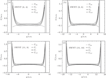
Fig. 1. Dependences of the image potential Uim calculated from the extended two-fluid model (dotted curve), repulsive potential Ur (dashed curve), and the resulting total potential Ut (solid curve) on proton position y from the center of a straight nanotube in the cases of (a) (6,4) SWNT, (b) (8,6) SWNT, (c) (11,9) SWNT, and (d) (15,10) SWNT. Also shown are the results for the total potential Ut1f calculated with Uim from the one-fluid model with zero damping (dash-dotted curve). The proton velocity is v = 3 a.u. Vertical solid bars represent the positions of nanotube walls. The values of nanotube radius R are 0.346, 0.483, 0.689, and 0.865 nm for the (6,4), (8,6), (11,9), and (15,10) SWNTs, respectively. Vertical dotted bars refer to the value Rasc for each nanotube, where asc is the nanotube atom screening radius.

Figure 1 shows how the image potential Uim from the extended two-fluid model, the repulsive potential Ur and the resulting total potential Ut depend on the proton position y in the yz plane from the center of a straight nanotube. Also shown are the results for the total potential Ut1f calculated with the image potential from the one-fluid model with zero damping. Vertical solid bars represent the nanotube walls. There are four types of nanotubes with the values of radius R of 0.346, 0.483, 0.689, and 0.865 nm for (6,4), (8,6), (11,9), and (15,10) SWNTs, respectively. Vertical dotted bars show the value Rasc for each nanotube. If the proton position reaches the outside of the region, ρ < Rasc during its motion through the nanotube, we treat that proton as dechanneled one and we do not follow its trajectory any more. In all cases in Fig. 1 the potential is cylindrically symmetric, i.e., Ui(y) = Ui(−y), (i = im,r,t). This figure also shows the influence of the image potential Uim on the total potential Ut. The total potential Ut is effectively lower if the image potential Uim is taken into consideration and becomes attractive towards the nanotube wall. When comparing the total potential calculated with the one-fluid model (Ut1f) and that obtained from the extended two-fluid models (Ut), one notices that in the former case the potential well is generally deeper throughout the nanotube, especially in the narrower nanotubes, and its attractive part is steeper towards the nanotube walls, especially in the broader nanotubes.

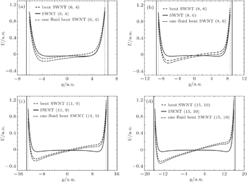
Figure 2 shows how the total potential Ut, calculated with the image potential Uim from the extended two-fluid model, depends on the proton position y from the center for each of the four types of bent and straight nanotubes. Also shown are the results for the total potential Ut1f calculated with the image potential from the one-fluid model with zero damping for the bent nanotubes. In the cases of bent nanotubes the total potential is no longer cylindrically symmetric and we cannot take Ut(y) = Ut(−y). This behavior of the potential function is a result of the centrifugal force that acts on the incoming proton. As the proton distance from the bent nanotube center increases, the differences in the potential are great compared with the case of the straight nanotubes. This may be rationalized by inspecting the expression for Ut(ρ) in Eq. (6), where we have an extra term that linearly depends on y. As a result, Ut(y) is attractive in a relatively large region of each nanotube, and the image potential Uim makes the attractive region increasingly deeper as the nanotube diameter increases. This effect of the image potential in the bent nanotubes is more pronounced in the case of the image potential from the one-fluid model with zero damping, but differences in comparison with the case of the image potential from the extended two-fluid model diminish as the nanotube diameter increases.

Fig. 2. Dependences of the total potential Ut calculated with the image potential Uim from the extended two-fluid model for straight (solid curve) and bent nanotube (dashed curve) on proton position y from the center of nanotubes in the cases of (a) (6,4) SWNT, (b) (8,6) SWNT, (c) (11,9) SWNT, and (d) (15,10) SWNT. Also shown are the results for the total potential Ut1f calculated with Uim from the one-fluid model with zero damping for the bent nanotubes (dash-dotted curve). The proton velocity is v = 3 a.u. The nanotube curvature angle is α = 4 mrad in the case of bent nanotubes. Vertical solid bars show the positions of nanotube walls. Vertical dotted bars represent the value Rasc for each nanotube, where R is the nanotube radius and asc is the nanotube atom screening radius.

From Figs. 1 and 2 one may conclude that while there are clearly some quantitative differences the total potential in the straight nanotube and that in the bent nanotube, which arise from using the image potential from the two versions of the hydrodynamic model, we do not expect to see any significant qualitative difference in our results for proton distributions between the one-fluid and the extended two-fluid models. Since the latter version of the hydrodynamic model has been recently scrutinized via direct comparison with several EELS experiments on different carbon nanostructures, we believe that, quantitatively speaking, the extended two-fluid model gives more reliable results than the previously used one-fluid model with zero damping.[1921] Hence, we adopt the extended two-fluid model to obtain the effects of image potential in our MC simulations of proton distributions in the bent nanotubes as shown in Figs. 36.

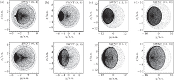
Fig. 3. Spatial distributions of protons channeled in bent nanotubes when the nanotube curvature angle is α = 4 mrad in the cases of: (a) (6, 4) SWNT, (b) (8, 6) SWNT, (c) (11, 9) SWNT, and (d) (15, 10) SWNT. The proton velocity is v = 3 a.u. and nanotube length L = 0.2 μm. In each of the upper panels the distribution is calculated without the image potential while in each of the lower panels the image potential is taken into account using the extended two-fluid model.
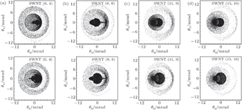
Fig. 4. Angular distributions of protons channeled in bent nanotubes when the nanotube curvature angle is α = 4 mrad in the cases of (a) (6, 4) SWNT, (b) (8, 6) SWNT, (c) (11, 9) SWNT, and (d) (15, 10) SWNT. The proton velocity is v = 3 a.u. and nanotube length L = 0.2 μm. In each of the upper panels, the distribution is calculated without the image potential while in each of the lower panel the image potential is taken into account using the extended two-fluid model.

Figure 3 presents spatial distributions of the protons channeled in the bent nanotubes with the curvature angle α = 4 mrad in the cases of (a) (6, 4) SWNT, (b) (8, 6) SWNT, (c) (11, 9) SWNT, and (d) (15, 10) SWNT. In the upper panels the distributions are calculated from proton trajectories obtained using the solid curves from Fig. 2 without the image potential, while in the lower panels the image potential is taken into account using the dashed curves from Fig. 2 based on the extended two-fluid model. By examining the areas with higher proton yield (darker shading) we may conclude that the presence of the image potential gives rise to seemingly broader proton beams, both in the direction of the y axis (lying in the nanotube bending plane) and in the direction of the x axis (perpendicular to the bending plane). The broadening effect appears to increase with increasing nanotube diameter. It is interesting that, inside wider nanotubes, the broadening in the perpendicular direction occurs over a relatively narrow, crescent-shaped region along the outer wall of the nanotube, which lies farther away from the center of curvature.

Figure 4 presents angular distributions of the protons channeled in the bent nanotubes with the curvature angle α = 4 mrad in the cases of (a) (6, 4) SWNT, (b) (8, 6) SWNT, (c) (11, 9) SWNT, and (d) (15, 10) SWNT. In the upper panels the distributions are calculated for proton trajectories using the solid curves from Fig. 2 without the image potential, while in the lower panels the image potential is taken into account using the dashed curves from Fig. 2 based on the extended two-fluid model. By examining the areas with higher proton yield (darker shading) we may conclude that the image potential gives rise to a significant redistribution of the proton flux, especially around the zero scattering angles (in the exit cross sections). Like the spatial distributions in Fig. 3, the presence of the image potential also seems to broaden the angular distributions in Fig. 4, albeit to a lesser degree than in Fig. 3. It is interesting that for the two broader nanotubes in Fig. 4, there is always some accumulation of the flux at the scattering angle θy ≈ −4 mrad, corresponding to undeflected protons, which is accentuated by the presence of the image potential.

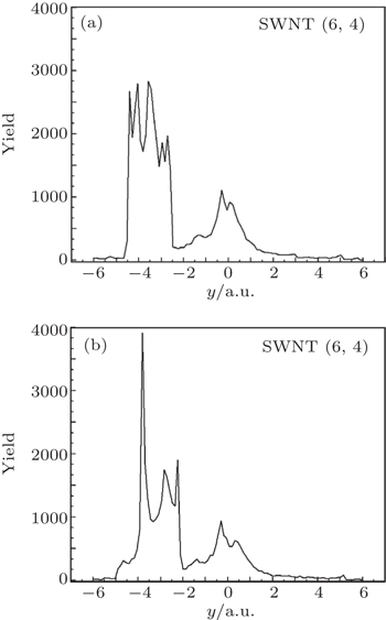
Fig. 5. Spatial distributions along the y axis for protons channeled in a bent (6, 4) SWNT when the nanotube curvature angle is α = 4 mrad, the proton velocity is v = 3 a.u. and nanotube length L = 0.2 μm, in the case where (a) image potential is not included and in the case where (b) image potential is included using the extended two-fluid model, respectively.

Figure 5 shows the spatial distributions of protons along the y axis, corresponding to the cross section with x = 0 in Fig. 3(a) for proton channeling in an SWNT(6,4) bent nanotube. We calculate the spatial distribution in the case where the image potential is not included (Fig. 5(a)) and in the case where the image potential is included (Fig. 5(b)). One may see in Figs. 5(a) and 5(b) that there are two main peak structures: one is in the central region of the nanotube, and the other is in the peripheral region towards the nanotube wall that is positioned farther away from the nanotube center of curvature. A close comparison of the two curves shows that while the presence of the image potential does not affect much the central peak, it gives rise to a slight broadening and a redistribution of the proton yield in the peripheral peak.

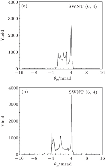
Fig. 6. Angular distributions along the θy axis for protons channeled in a bent (6, 4) SWNT when the nanotube curvature angle is α = 4 mrad, the proton velocity is v = 3 a.u. and nanotube length L = 0.2 μm, in case where (a) image potential is not included and in the case where (b) image potential is included using the extended two-fluid model.

Figure 6 shows the angular distributions of protons along the θy axis, corresponding to the cross section with θx = 0 in Fig. 4(a) for proton channeling in an SWNT(6,4) bent nanotube. We calculate the angular distribution in the case where the image potential is not included (Fig. 6(a)) and in the case where the image potential is included (Fig. 6(b)). We see that the image potential contributes to a generally broader distribution of angles, accompanied with a significant redistribution of the proton flux. In particular, while figures 6(a) and 6(b) both show a peak at θy ≈ 4 mrad, corresponding to a deflection that doubles the bending angle α = 4 mrad due to single hard collision with the nanotube wall, and the nanotube with the image potential also shows peaks at θy ≈ 0 and even θy ≈ −4 mrad. It is surprising that in the case of latter peak, such a narrow nanotube still favors the direction almost with no bending in the presence of the image potential.

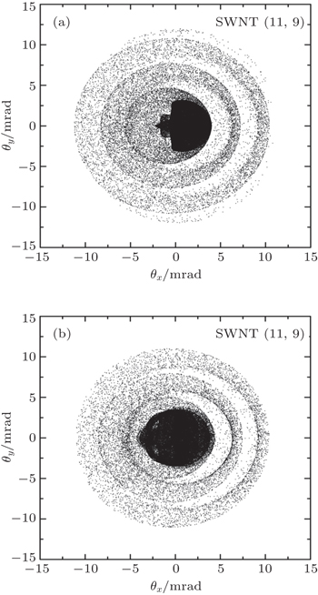
Fig. 7. Angular distributions of protons channeled in bent nanotubes when the nanotube curvature angle is α = 4 mrad in the case of a (11, 9) SWNT. The proton velocity is v = 3 a.u. and nanotube length L = 0.5 μm. The distributions are calculated using the extended two-fluid model without (a) and with (b) taking into account the image potential.

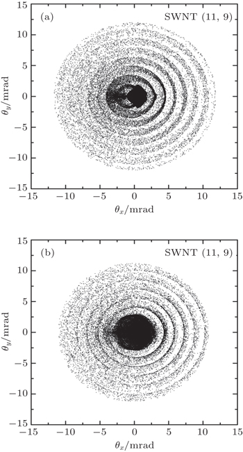
Figures 7 and 8 show the angular distributions of the protons channeled in the bent nanotubes with the curvature angle α = 4 mrad in the cases of (11, 9) SWNT nanotube with the lengths L = 0.5 μm and L = 1 μm, respectively. In Fig. 8(a) the distributions are calculated without considering the image potential, while in Fig. 8(b) the image potential is taken into account. We can notice the concentric circular maxima appear in the angular distributions. With the increase of the nanotube length their number increases, whereas their spacings appear to be equidistant. The number of the concentric maxima is related to the number of proton deflections from the nanotube wall. We may conclude from Figs. 7 and 8 that the image potential gives rise to a significant redistribution of the proton flux, especially around the zero scattering angle (in the central part of the scattering angle plane).

Fig. 8. The same as in Fig. 7, but for the nanotube length L = 1 μm.
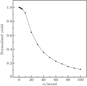
Fig. 9. The normalized yield of 3 a.u. protons transmitted through a (11, 9) SWCNT of the length L = 0.2 μm versus nanotube bending angle α in a range between 0 and 100 mrad. The initial number of protons is about 7.8 × 10⁴.

In Fig. 9 we plot the normalized yield of 0.223 MeV protons transmitted through a (11, 9) SWCNT of length L = 0.2 μm. The nanotube bending angle, α, is varied between 0 and 100 mrad. We can see that for bending angle α = ψc = 11 mrad (critical angle for channeling) about 90% of the initial number of protons remains channeled. For α = 2ψc about 60% of the initial number of protons remains, because the nanotube is very short and majority of protons make less than one oscillation. For a few times longer nanotube, if α > ψc all protons would be dechanneled. Thus, for the bending angle α = 4 mrad and the length L = 0.2 μm that are chosen in Figs. 36, almost all the initial protons remain channeled.

Next, we provide the main reasons for choosing the values of proton energy and the nanotube lengths in this work.

Future developments in our work will be concerned with simulations for longer nanotubes that include the effects of energy loss of channeled protons and the angular uncertainty because of the proton collisions with the nanotube electrons in the presence of the dynamic polarization of the nanotube electrons.

4. Conclusions

In this work, we study the channeling of protons that move at a speed of 3 a.u. through four different types of straight and bent SWNTs, namely (6, 4), (8, 6), (11, 9), and (15, 10). The effects of dynamic polarization of the valence electrons in the nanotube wall are assessed by both the one-fluid hydrodynamic model and an extended two-fluid hydrodynamic model. According to those models, we calculate the image potential for protons and combine it with the Doyle–Turner repulsive potential to obtain the total potentials in the straight and bent carbon nanotubes respectively. We then calculate individual proton trajectories by solving the classical equation of motion in a total potential based on the image potential from the extended two-fluid model. Finally, a Monte Carlo (MC) code is used to compute the spatial and angular distributions of protons channeled through short and bent nanotubes respectively. In the MC code we use the parameters for the extended two-fluid hydrodynamic model, which were determined in recent applications in the modelling of several independent experiments on electron energy loss spectra of different carbon nanostructures.[31] Therefore, compared with our previous studies of the image potential effects in ion channeling that were based on a one-fluid model with zero damping for a quasi-free electron gas in nanotubes, this work provides a complete and accurate description of the dynamic polarization effects.

The results show that the presence of the image potential in a bent nanotube broadens and deepens the attractive potential well, which happens in each nanotube due to the centrifugal force in a non-inertial frame of reference for proton motion. As a consequence, the spatial distributions of the channeled protons in the presence of the image potential are generally broader in the directions that are parallel and perpendicular to the bending plane of all four types of nanotubes. Angular distributions also exhibit broadening, but to a lesser extent than the spatial distributions, which is accompanied with a significant redistribution of the proton flux that follows the nanotube bending angle. Overall, there is a tendency for the image potential to increase both the proton yield in the spatial distributions and the proton flux in the angular distributions, in the peripheral regions of the nanotubes, away from the bending center.

All our findings indicate that the influence of the dynamic polarization on ion channeling through bent carbon nanotubes in the MeV energy range is strong and it should not be omitted in simulations. In particular, the presence of the image potential may diminish the bending efficiency of carbon nanotubes for charged particles that move in the range of speeds of several Bohr velocities.

Reference
1Klimov V VLetokhov V S 1996 Phys. Lett. 222 424
2Dedkov G V 1998 Nucl. Instrum. Method Phys. Res. 143 584
3Zhevago N KGlebov V I 1998 Phys. Lett. 250 360
4Gevorgian L AIspirian K AIspirian R K 1998 Nucl. Instrum. Method Phys. Res. 145 155
5Biryukov V MBellucci S 2002 Phys. Lett. 542 111
6Artru XFomin S PShulga N FIspirian K AZhevago N K 2005 Phys. Rep. 412 89
7Krasheninnikov A VNordlund K2005Phys. Rev. B7124540
8Matyukhin S IFrolenkov K Y 2007 Tech. Phys. Lett. 33 58
9Moura C SAmaral L2007Carbon45185
10Zheng L PZhu Z YLi YZhu D ZXia H H 2008 Nucl. Instrum. Method Phys. Res. 266 849
11Mišković Z L 2007 Radiat. Eff. Def. Solids 162 185
12Borka DPetrović SNešković N2011Channeling of Protons Through Carbon NanotubesNew YorkNova Science Publishers ISBN 978-1-61122-050-61
13Li YZheng L PZhang WXu Z JRen C LHuai PZhu Z Y 2011 Chin. Phys. Lett. 28 066101
14Cui S WZhu R ZWang X SYang H X 2014 Chin. Phys. 23 106105
15Zhu ZZhu DLu RXu ZZhang WXia H2005Proceedings of the International Conference on Charged and Neutral Particles Channeling PhenomenaVol. 5974 SPIE, Bellingham, Washington13–1
16Chai GHeinrich HChow LSchenkel T 2007 Appl. Phys. Lett. 91 103101
17Zhang Y YZhao DYou S YSong Y HWang Y N 2013 Chin. Phys. Lett. 30 096103
18Zhang Y YSun J ZSong Y HMišković Z LWang Y N 2014 Carbon 71 196
19Borka DPetrović SNešković NMowbray D JMišković Z L 2006 Phys. Rev. 73 062902
20Borka DMowbray D JMišković Z LPetrović SNešković N 2008 Phys. Rev. 77 032903
21Borka DMowbray D JMišković Z LPetrović SNešković N 2010 New J. Phys. 12 043021
22Nešković NPetrović SBorka D 2005 Nucl. Instrum. Method Phys. Res. 230 106
23Nešković NBorka DŠopić SPetrović S2010Int. J. Nonlinear Sci. Numer. Simul.111131
24Matyukhin S I 2009 Tech. Phys. Lett. 35 318
25Mowbray D JSegui SGervasoni J LMišković Z LArista N R 2010 Phys. Rev. 82 035405
26Nelson F JIdrobo J CFite J DMišković Z LPennycook S JPantelides S TLee J UDiebold A C 2014 Nano Lett. 14 3827
27Segui SMišković Z LGervasoni J LArista N R 2013 J. Phys.: Condens. Matter 25 175001
28Li C ZMišković Z LGoodman F OWang Y N 2013 J. Appl. Phys. 113 184301
29Radović IBorka DMišković Z L 2014 Phys. Lett. 378 2206
30Karbunar LBorka DRadović IMišković Z L 2015 Nucl. Instrum. Method Phys. Res. 358 82
31Borka Jovanović VRadović IBorka DMišković Z L 2011 Phys. Rev. 84 155416
32Lindhard J1965K. Dan, Vidensk. Selsk., Mat.-Fys. Medd.341
33Doyle P ATurner P S 1968 Acta Crystallogr. 24 390
34Saito RDresselhaus GDresselhaus M S2001Physical Properties of Carbon NanotubesLondonImperial College Press1
35Feldman L CMayer J WPicraux S T1982Materials Analysis by Ion ChannelingNew YorkAcademic Press
36Borka DLukić VTimko JBorka Jovanović V 2012 Nucl. Instrum. Method Phys. Res. 279 169
37Borka DLukić VTimko JBorka Jovanović V 2012 Nucl. Instrum. Method Phys. Res. 279 198
38Petrović SBorka DTelečki INešković N 2009 Nucl. Instrum. Method Phys. Res. 267 2365
39Sun XZaric SDaranciang DWelsher KLu YLi XDai H 2008 J. Am. Chem. Soc. 130 6551
40Petrović STelečki IBorka DNešković N 2008 Phys. Lett. 372 6003