


Study of the temperature rise induced by a focusing transducer with a wide aperture angle on biological tissue containing ribs
[Wang Xin1, Lin Jiexing1, Liu Xiaozhou1, 2, †,  , Liu Jiehui1, Gong Xiufen1]
, Liu Jiehui1, Gong Xiufen1]
|
|


† Corresponding author. E-mail:
Project supported by the National Basic Research Program of China (Grant Nos. 2012CB921504 and 2011CB707902), the National Natural Science Foundation of China (Grant No. 11274166), the Fundamental Research Funds for the Central Universities, China (Grant No. 020414380001), the Fund from State Key Laboratory of Acoustics, Chinese Academy of Sciences (Grant No. SKLA201401), China Postdoctoral Science Foundation (Grant No. 2013M531313), and the Priority Academic Program Development of Jiangsu Higher Education Institutions and SRF for ROCS, SEM.
We used the spheroidal beam equation to calculate the sound field created by focusing a transducer with a wide aperture angle to obtain the heat deposition, and then we used the Pennes bioheat equation to calculate the temperature field in biological tissue with ribs and to ascertain the effects of rib parameters on the temperature field. The results show that the location and the gap width between the ribs have a great influence on the axial and radial temperature rise of multilayer biological tissue. With a decreasing gap width, the location of the maximum temperature rise moves forward; as the ribs are closer to the transducer surface, the sound energy that passes through the gap between the ribs at the focus decreases, the maximum temperature rise decreases, and the location of the maximum temperature rise moves forward with the ribs.
Biomedical ultrasound is one of the most active fields in modern ultrasonic technology, with ultrasonic diagnosis and treatment now widespread in biomedicine. The main application of biomedical ultrasound in clinical diagnosis is ultrasonic imaging such as B-ultrasound and D-ultrasound. Clinical treatment applications are mainly limited to ultrasonic lithotripsy and high intensity focused ultrasound based on cavitation and heat effects.[1] High intensity focused ultrasound can make a focal area of tissue produce relatively large vibrations which are able to break up stones,[2,3] and it is also an important medical technology in modern cancer treatment. The treatment principle of this technique is to achieve high sound intensity (103 W/cm2–104 W/cm2) by focusing sound energy generated by a large ultrasonic focusing transducer to achieve a high temperature (above 65 °C) in a focal area in a short period of time, causing tumor tissue to undergo thermal coagulation necrosis thus killing cancerous cells.[4,5] High frequency ultrasound has better directivity and most of the sound energy can be focused on a target area without affecting surrounding tissues by accurate control of the ultrasonic focus, therefore it can realize noninvasive treatment.[6,7] In practical applications, a sound wave generated by the transducer will pass through multiple biological media before reaching tumor tissue, and it is difficult to avoid reflection and scattering of sound energy because of the mismatch of acoustic impedance between different media, thus affecting the sound field of the target area, and distorting the sound field accordingly. Particularly in the treatment of liver cancer, the presence of the ribs can greatly influence the sound and temperature field, and ultimately affect the efficacy of the treatment. In early clinical treatments, surgical removal of ribs was often used to prevent reflections of ultrasound energy from affecting the stability of the sound field. Consequently, effective prediction of the distribution of the sound and temperature fields behind the ribs becomes very necessary in order to realize noninvasive treatment. Kamakura et al. used an ellipsoidal coordinate system to develop the spheroidal beam equation (SBE) based on the Westervelt equation.[8] The SBE includes nonlinearity, diffraction, and absorption effects, and can be used to predict the sound field of a transducer with a wide aperture angle.[8,9] Li et al. used the implicit-prediction correction method to calculate the influence of the ribs on a sound field under a cylindrical coordinate system using the Khokhlov–Zabolotskaya–Kuznetsov (KZK) equation[10] while Liu et al. studied its temperature field.[11] Lin et al. simulated and obtained the sound field of tissues behind ribs by focusing a transducer with a wide aperture angle under a three-dimensional ellipsoidal coordinate system using the SBE model.[12] Fan et al. calculated the nonlinear sound field of a strong focusing transducer with a wide aperture angle using the SBE model,[13,14] while Qian et al. investigated the influence of sound source parameters and material characteristics on the nonlinear effect of a concave spherical self-focusing sound field using the SBE model.[15]
Previous articles generally analyze the sound field of a focusing transducer with a small aperture angle.[8–10] Liu et al. studied the temperature field caused by weakly focused ultrasound[11] and Lin et al. simulated and obtained the sound field of tissues behind ribs by focusing a transducer with a wide aperture angle.[12] However, the innovative point of this paper is that we analyze the temperature field of a focusing transducer with a wide aperture angle on biological tissue containing ribs using the SBE model. In the paper, we first used the SBE to calculate the sound field produced by a focusing transducer with a wide aperture angle to obtain heat deposition, and then solved the Pennes bioheat equation to obtain the resulting temperature field in a biological tissue with ribs and study the effects of rib parameters on the temperature field.
The KZK equation is only suitable for a transducer with a half-aperture angle less than 16.6° due to the use of the parabolic or paraxial approximation, and the SBE equation can be used for a transducer with a wide half-aperture angle. A focusing transducer with a wide aperture angle is a spherical-shell focusing transducer with a spherical half-angle greater than 16.6°.[16] Because such a wide angle focusing transducer has a larger radiating area, stronger focusing effect, smaller focal area radius and better penetrability than that of a small angle focusing transducer, a greater temperature rise can be generated within a tumor while reducing damage to other normal tissues.[17]
Figure
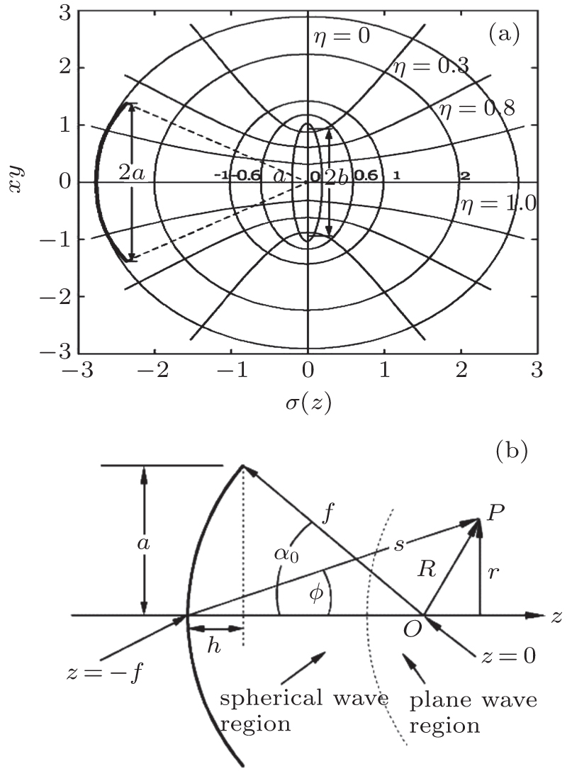 | Fig. 1. The ellipsoidal coordinate system and the division of the sound field, panel (a) is the schematic diagram of the ellipsoidal coordinate system, panel (b) shows the spherical wave area and a planar wave area. |
As in Fig.
We calculated the sound field under the ellipsoidal coordinate system, and established the conversion relationship between the three coordinates (σ, η, ϕ) of the ellipsoidal coordinate system and the three coordinates (x, y, z) of the rectangular coordinate system:[12]
The Westervelt equation can be written as follows:[16]

In the spherical wave area, the retarded time pertinent to the spherical wave is introduced:

In the planar wave area, the retarded time pertinent to the planar wave is introduced:


Consolidating Eq. (

The normalized sound pressure is represented as the following Fourier series expansion:


The heat deposition can be expressed as:


The Pennes bioheat equation[20] can be written as:

Because we study biological tissues in vitro, no heat flow from blood circulation exists, so that wb can be neglected, Qm can also be neglected in dead tissues. So the Pennes equation can be written as:

In the oblate spheroidal coordinate system, the Laplace operator
By substituting Eq. (

The matrix chase-after method (Thomas algorithm) is used to solve Eq. (
(i) In this paper, Tables
| Table 1. Sound field parameters.[22] . |
| Table 2. Temperature field parameters.[22] . |
(ii) Temperature rise in biological tissue without ribs
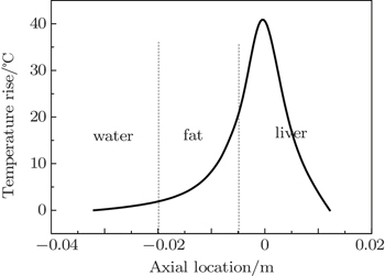
In order to guarantee the correctness of the simulation model, we should first compare the simulation results with actual values reported in the literature.[22]
Figure
 | Fig. 2. The axial temperature rise in tissue without ribs when the radius of the focusing transducer is 10 mm. |
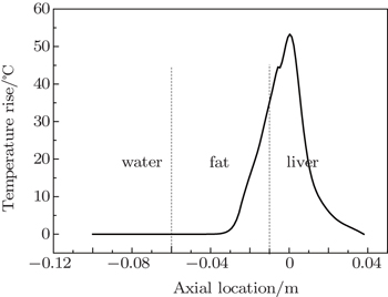
Figure
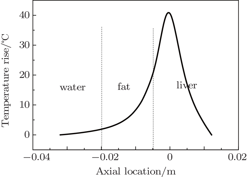
 | Fig. 3. The axial temperature rise in tissue without ribs when the radius of the focusing transducer is 50 mm. |
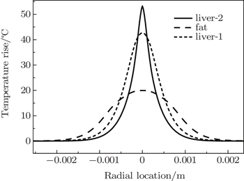
Figure
 | Fig. 4. The radial temperature rise in tissue without ribs at different axial locations. |
(iii) Temperature rise of a biological tissue with two ribs located symmetrically on either side of the axis
Next, we investigated the influences of the initial sound pressure, frequency, half-angle of the transducer, gap width and the location of ribs on the temperature rise of biological tissues under the condition that the half-angle is 17.5°, 23.6°, and 30° respectively. The locations of fat, liver and two ribs are shown in Fig.
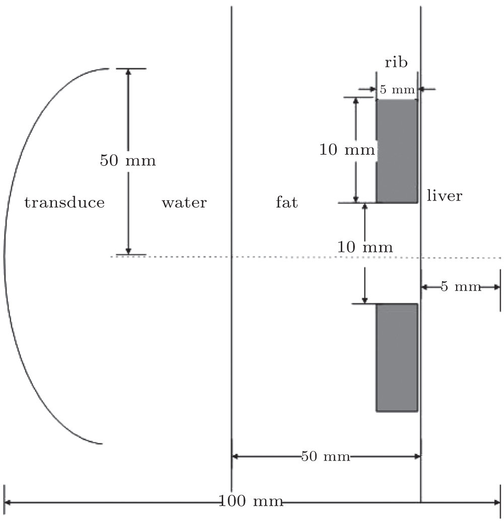 | Fig. 5. The tissue with two ribs located symmetrically on both sides of the axis. |
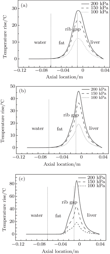
Figure
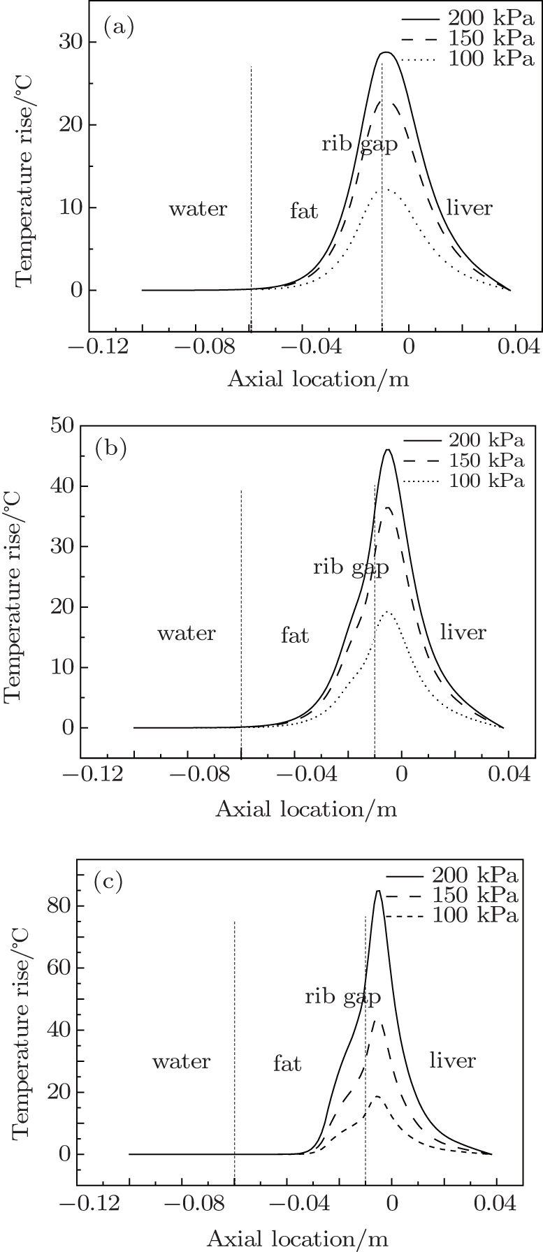 | Fig. 6. The axial temperature rise in tissue with two ribs at different sound pressures under the condition that the half-angle is (a) 17.5°, (b) 23.6°, and (c) 30° respectively. |
Figure
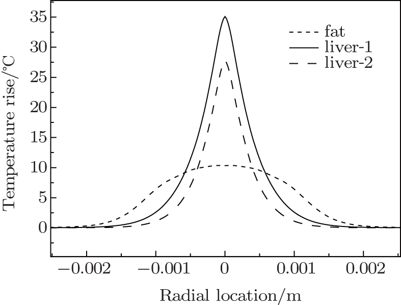 | Fig. 7. The radial temperature rise in tissue with two ribs at different axial locations under the condition that the half-angle is 30°. |
Figure
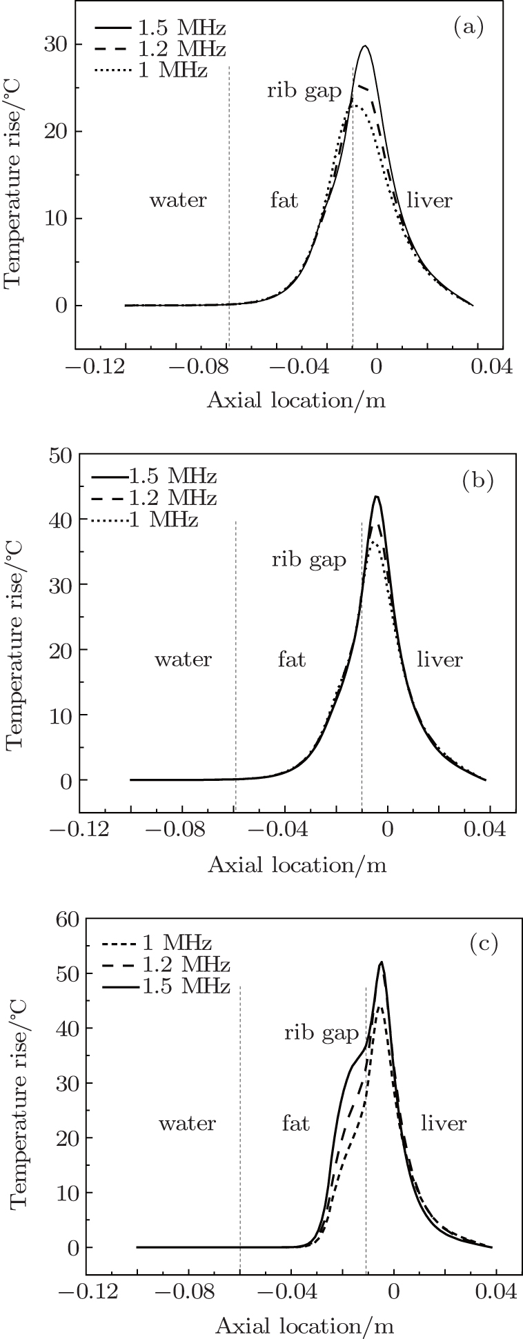 | Fig. 8. The axial temperature rise in tissue with two ribs at different frequencies under the condition that the half-angle is (a) 17.5°, (b) 23.6°, and (c) 30° respectively. |
Figure
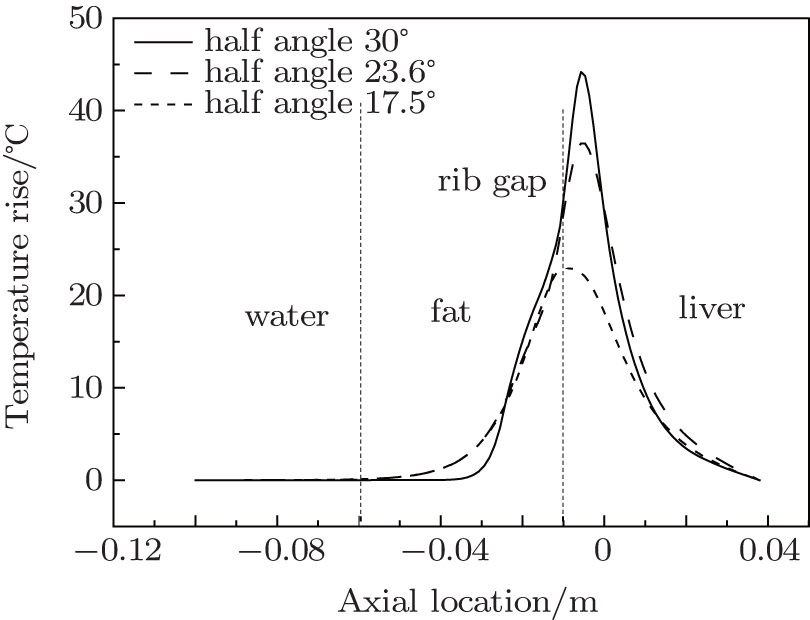 | Fig. 9. The axial temperature rise in tissue with two ribs at different half-angles. |
Figure
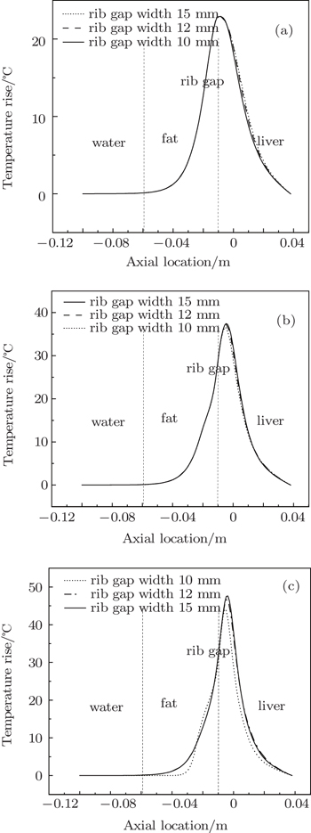
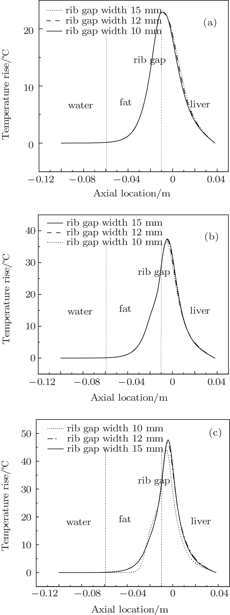 | Fig. 10. The axial temperature rise in tissue with two ribs at different rib gap widths under the condition that the half-angle is (a) 17.5°, (b) 23.6°, and (c) 30° respectively. |
Figure
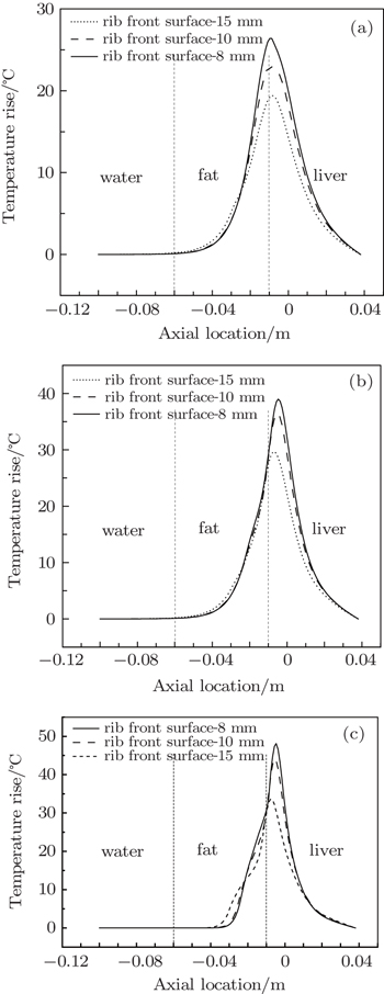
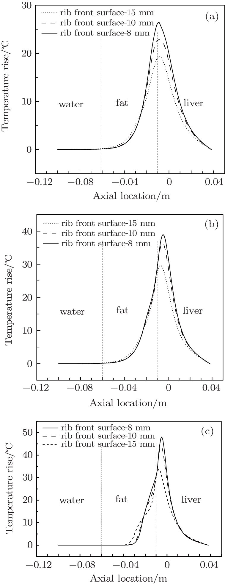 | Fig. 11. The axial temperature rise in tissue with ribs at different distances between the front surface of the rib gap and the geometric focus under the condition that the half-angle is (a) 17.5°, (b) 23.6°, and (c) 30° respectively. |
From the results of our simulation, it can be seen that the influence of ribs on the temperature field in biological tissue is very obvious. The location and the gap width of the ribs both have a great influence on the temperature rise of biological tissue. As two ribs are distributed on either side of the axis, a sound wave can pass through the rib gap, so there is a relatively high temperature rise in the liver. As the gap width between the ribs increases, the sound energy that passes through increases, so the temperature rise of the liver also increases. As the ribs are closer to the focusing transducer, the focusing effect decreases and less sound energy passes through the rib gap, so the temperature rise of the liver decreases. Consequently if we want to achieve a higher temperature rise in the liver, in addition to increasing the initial sound pressure or the half-angle of the focusing transducer, we can also increase the distance between the transducer and the ribs. This work can provide guidance for the practical treatment of liver cancer.
| 1 | |
| 2 | |
| 3 | |
| 4 | |
| 5 | |
| 6 | |
| 7 | |
| 8 | |
| 9 | |
| 10 | |
| 11 | |
| 12 | |
| 13 | |
| 14 | |
| 15 | |
| 16 | |
| 17 | |
| 18 | |
| 19 | |
| 20 | |
| 21 | |
| 22 |