Linear theory of beam–wave interaction in double-slot coupled cavity travelling wave tube
He Fang-ming1, 2, Xie Wen-qiu3, 4, Luo Ji-run3, †, , Zhu Min3, Guo Wei3
Radar Research (Beijing), Leihua Electronic Technology Institute, AVIC, Beijing 100017, China
Aviation Key Laboratory of Science and Technology on AISSS, Wuxi 214063, China
Institute of Electronics, Chinese Academy of Sciences, Beijing 100190, China
University of Chinese Academy of Sciences, Beijing 100039, China


† Corresponding author. E-mail: luojirun@mail.ie.ac.cn

Project supported by the National Natural Science Foundation of China (Grant No. 11205162).

Abstract
Abstract

A three-dimensional model of the double-slot coupled cavity slow-wave structure (CCSWS) with a solid round electron beam for the beam–wave interaction is presented. Based on the “cold” dispersion, the “hot” dispersion equation is derived with the Maxwell equations by using the variable separation method and the field-matching method. Through numerical calculations, the effects of the electron beam parameters and the staggered angle between adjacent walls on the linear gain are analyzed.

1. Introduction

The traveling wave tube with the coupled cavity slow wave structure (CCSWS) is well known for its ability to generate high peak and average powers as well as the moderate bandwidth.[1,2] As one of the most essential members of the CCSWS family, the double-slot CCSWS is more likely to be used at a higher voltage than the Hughes structure, which means a larger microwave output power.

The equivalent circuit model is the commonly used beam wave interaction method of the CCSWS. However, the parameters of this circuit are obtained from the experiment or the simulation software, as this model cannot directly provide a precise dispersion relation in the whole band from the geometrical dimensions.[35] In Ref. [6], the authors analyzed the high frequency characteristics of the double-slot CCSWS by building up a theoretical model using the boundary field matching method and the Green’s function, and the numerical results showed that the dispersion and interaction impedance calculated by this model are in good agreement with those calculated by the Ansoft HFSS code and the experimental results. Based on the above works, the “hot” dispersion equation, which describes the beam–wave interaction, was derived by using the self-consistent field theory and the boundary field matching method.[7,8] Then the influence of the beam parameters and the structure parameters on the small signal gain were investigated and discussed based on the numerical calculation.

2. Model and theory

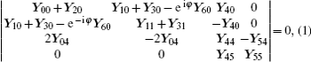
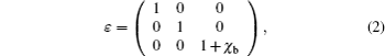
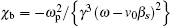
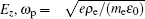
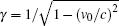
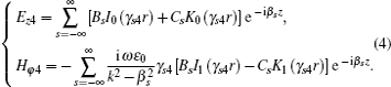
For the double-slot CCSWS, the two slots on one wall are usually staggered by an angle of 180° from one to the other. The “cold” dispersion equation of the structure is[6]

where Y00Y55 are m × n matrices, with m and n being the orders of the series expansion in the Galerkin method. Theoretically speaking, m and n tend toward infinity, whereas they are both truncated to be finite in practice. The Y00Y55 are functions of both frequency and dimensions of the system and can be derived by matching the boundary field and using the equivalent principle in conjunction with the Green’s function techniques. The matrices Y10, Y30, Y11, and Y31 are relevant to ψ, which is defined as the staggered angle between two adjacent walls and ranges from 0 to 90° for a double-slot CCSWS. The factor e−jφ, i.e., e−jβz, represents the wave propagating along +z, where φ is the phase shift of one period and β is the axial wave number. Changing the phase shift φ from 0 to π, the dispersion relation can be obtained by solving Eq. (1).

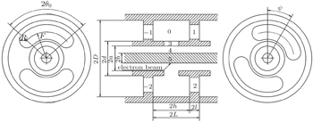
The configuration of the double-slot CCSWS, in which the guided waves interact with a solid round electron beam, is shown in Fig. 1. The electron beam is assumed to be immersed in an infinite magnetic field in the axial direction. Thus, it propagates uniformly along the z axis of the system with a velocity v0. By linearizing the Lorentz-force equations and the Maxwell equations, beam region 5 can be replaced by an equivalent anisotropic dielectric layer with an effective permittivity constant as follows:[9]

where reflects the electron polarization response to the perturbing field component is the plasma frequency, e and me denote the electron charge and the electron rest mass, respectively, ρe = J/v0 is the electron density, J = I/(πb2) is the current density, , I and V are the electron beam current and voltage, respectively, is the relativistic factor, and βs = β0 + /L is the axial wave number of the s-th space harmonic. Hence, the problem can be replaced by an equivalent multilayer dielectric field problem.

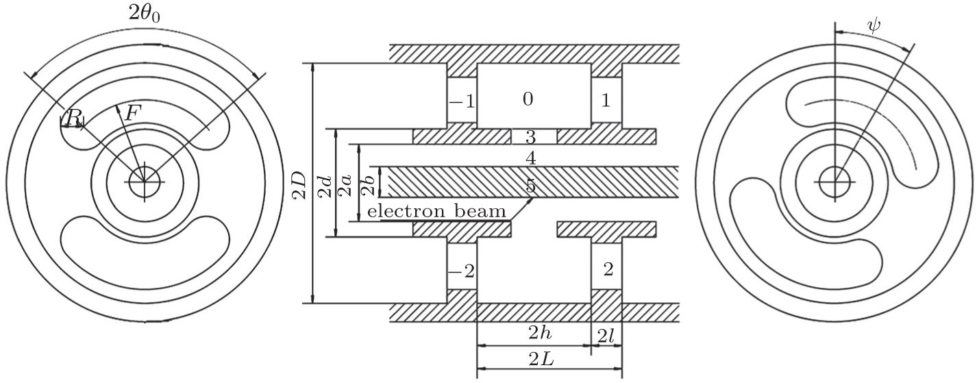
Fig. 1. Doubleslot coupled cavity.

It can be seen from Eq. (1) that only Y55 is relevant to the drift tunnel.[6] For the hot dispersion equation, it can also be obtained by the method of moment in conjunction with the Green’s function, while the form of the equation is the same as Eq. (1). The differences between the hot dispersion and the cold one only lie in the following factors: (i) the specific form of Y55, which is affected by the electron beam; (ii) the phase shift φ = β−1 · 2L. Thus, by employing the boundary field matching method to deduce the specific form of Y55, the complete form of the hot dispersion equation can be obtained.

Based on the above analysis, the axial electric field component Ez of the TM mode in the drift tunnel can be obtained from the Helmholtz equation by employing the method of variable separation, while the transverse magnetic field component Hφ can then be expressed in terms of the corresponding Ez.

In region 5 (0 < r < b),

In region 4 (b < r < a),

Here is the propagation constant in free space, and As, Bs, Cs are coefficients to be determined.

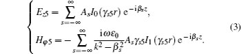
The boundary conditions of the tangent field components at r = b are

Then, the boundary condition at r = a is

where e5 is the surface electric field at r = a[6]

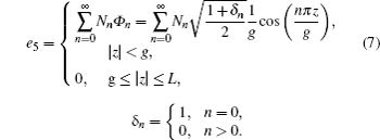
It is assumed that the electromagnetic field in each region is excited by the surface electric fields, so the magnetic field in region 4 can also be written as follows:[6]

Substituting Eqs. (3), (4), and (7) into Eqs. (5) and (6), then combining with Eq. (8), we can obtain the specific form of the electromagnetic vector operator L4{Φn}, which is only relevant to the dimensions of the structure, the frequency, and the axial wave number. Thus, the second term of the admittance matrix element Y55 can be deduced, which is the only difference between the structures with and without the electron beam. The complete formula of Y55 with the electron beam can be written as follows:

where

In the absence of the electron beam (I → 0), equation (9) degenerates to the following form:

which is consistent with that in the cold dispersion.[6]

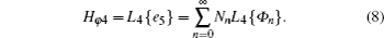
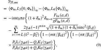
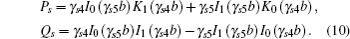
Thus, by substituting Eq. (9) in Eq. (1), the hot dispersion equation can be obtained. When the parameters of the electron beam and the geometrical dimensions of the structure are given, the relationship between the frequency f and the propagation constant β−1 can be evaluated by solving the complex transcendental equations. Hence, the small signal gain (dB/period) can be obtained as

where Im denotes the imaginary part of a complex number.

3. Results and discussion

In order to illustrate the above theory, a special case of the Ka-band CCSWS with double staggered slots (Ψ = 90°) is employed. Table 1 lists the geometrical dimensions of the structure used in the computations.

Figure 2 shows the plots of the small signal gain versus frequency for a variety of beam voltages, while the beam current is fixed. It can be seen from the figure that the operating band narrows and moves to a lower frequency range, while the maximum gain augments as the beam voltage increases. This effect is attributed to the increase of the beam velocity.[10]

Table 1.

Dimensions of the Ka-band double-slot CCSWS used for simulation and analysis.

.
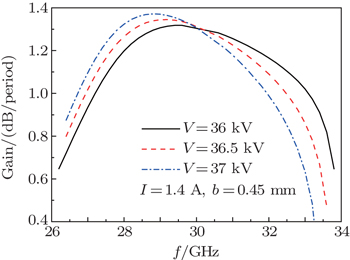
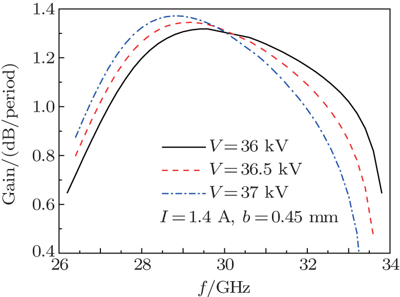
Fig. 2. Effect of V on the small signal gain.

Figure 3 shows the plots of the small signal gain versus frequency for a variety of beam currents, while the beam voltage is fixed. It can be seen from the figure that the increase of the beam current leads to a broader operating band and the augment of the gain, which accords with the Pierce theory.[10] However, the poor impact of the large current on the flow rate should also be considered from the engineering point of view.

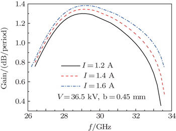
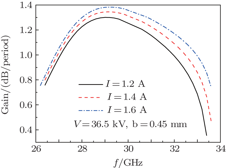
Fig. 3. Effect of I on the small signal gain.

Then, the gain characteristics of two common double-slot CCSWS, the ones with in-line slots (ψ = 0°) and staggered slots (ψ = 90°), are investigated. To illustrate this issue more clearly, the high frequency characteristics of these two structures are shown in Fig. 4 firstly. The dimensions of both structures are shown in Table 1, and the results are obtained by the theoretical model in Ref. [6]. Compared to the in-line structure, the staggered one has a larger bandwidth for that the lower band edge extends. As for the interaction impedance, the staggered one has a lower value at the lower band and a slightly higher value at the upper band where the impedance curve flattens. The small signal gain characteristics of these two structures with different synchronous voltages (37 kV, 36.5 kV) and fixed beam current (I = 1.4 A, b = 0.45 mm) are shown in Fig. 5. According to the Pierce theory, the gain is proportional to a third root of the characteristic impedance.[10]

Comparison of the high frequency characteristics of the Ka-band CCSWS with in-line (ψ = 0°) and overlap staggered (ψ = 90°) double slots.

Comparison of the small signal gain of the Ka-band CCSWS with in-line (ψ = 0°) and overlap staggered (ψ = 90°) double slots.

Thus, the staggered structure has a larger operating bandwidth and a smaller maximum gain than the in-line structure, which is consistent with the high frequency characteristics discussed before. That is to say, the in-line structure is suitable to the requirement of high power, while the staggered structure keeps a better balance between the bandwidth and the gain.

4. Summary and conclusion

The hot dispersion equation for the double-slot coupled cavity slow-wave structure (CCSWS) with arbitrary staggered angle between two adjacent walls was developed by means of the self-consistent field theory. The influence of the beam parameters and the staggered angle between adjacent walls on the small signal gain was illustrated by numerical calculations. The results of the calculations show that, as the beam voltage and current increase, the maximum gain will augment. Meanwhile, the former factor will lead to a lower frequency range and a narrower bandwidth, whereas the latter factor has a great influence on the bandwidth. The analysis also indicates that, for the CCSWS with double in-line slots (ψ = 0°) and staggered slots (ψ = 90°) with the same dimensions, the former one is suitable to the requirement of high power, while the latter one keeps a better balance between the bandwidth and the gain, and has potential for application in medium-bandwidth high-power TWTs. This paper introduces a fast method to obtain the gain from the geometrical and electrical dimensions directly, which is helpful for the engineering design.

Reference
1Cusick MBegum RGajaria DGrant TKolda PLegarra JMeyer CRamirez-Aldana J LPedro D SStockwell BYamane G201213th IEEE International Vacuum Electronics Conference (IVEC 2012)April 24–26, 2012Monterey, USA227
2Wang BXie W K2007Acta Phys. Sin56567138(in Chinese)
3Freund H PThomas MAntonsen JZaidman E GLevush BLegarra J 2002 IEEE Trans. Plasma Science 30 1024
4Chernin DThomas MAntonsen JChernyavskiy I AVlasov A NLevush BBegum RLegarra J R 2011 IEEE Trans. Electron Devices 58 1229
5Bai C JLi JQ Hu Y LYang Z HLi B2012Acta Phys. Sin61178401(in Chinese)
6He F MLuo J RZhu MGuo W2013IEEE Trans. Electron Devices60774
7Freund H PKodis M AVanderplaats N R 1992 IEEE Trans. Plasma Science 20 543
8Liu YXu JLai J QXu XShen FWei Y YHuang M ZTang TGong Y B 2012 Chin. Phys. B 21 074202
9Lawson J D1988The Physics of Charged ParticlesOxfordClarendon Pressp. 293
10Gilmour A S2011Principles of Klystrons, Traveling Wave Tubes, Magnetrons, Crossed-Field Amplifiers and GyrotronsNorwoodArtech Housep. 422