A subwavelength metal-grating assisted sensor of Kretschmann style for investigating the sample with high refractive index
Li Xu-Feng1, †, , Peng Wei2, Zhao Ya-Li3, Wang Qiao2, Wei Ji-Lin1
School of Applied Science, Taiyuan University of Science and Technology, Taiyuan 030024, China
School of Physics and Optoelectronic Technology, Dalian University of Technology, Dalian 116024, China
No. 33 Research Institute of China Electronics Technology Group Corporation, Taiyuan 030024, China


† Corresponding author. E-mail: xfli@mail.dlut.edu.cn

Project supported by the National Natural Science Foundation of China (Grant Nos. 61137005 and 61178067), the Science Foundation of Shanxi Province, China (Grant No. 2013021004-3/2014021021-1), the Pre-studied Project on Weapon Equipment, China (Grant No. 201262401090404), and the Specialized Research Foundation for Doctor of School, China (Grant No. 20122027).

Abstract
Abstract

In this paper, a subwavelength metal-grating assisted sensor of Kretschmann style that is capable of detecting the sample with a refractive index higher than that of the substrate is proposed. The sensor configuration is similar to the traditional Kretschmann structure, but the metal film is pattered into a grating. As a TM-polarized laser beam impinges from the substrate, a resonant dip point in reflectance curve is produced at a certain incident angle. Our studies indicate that the sensing sensitivity and resolution are affected by the grating’s gap and period, and after these parameters have been optimized, a sensing sensitivity of 51.484°/RIU is obtained with a slightly changing resolution.

1. Introduction

Surface plasmons (SPs) are electromagnetic waves that propagate along a conductor surface, whose electric field has a maximum at the surface and decays exponentially. SPs are excited generally through a coupling of an evanescent field generated by a TM-polarized light in attenuated total reflection (ATR).[1,2] Owing to the resonant condition, the excited SP that is very sensitive to the variation in refractive index of the surrounding environment. ATR offers a potential for exploring a sensor based on surface plasmon resonance (SPR). Over recent decades, since the dramatic progress made in micro-nano-fabrication technology,[35] ATR has became a useful tool in many areas, such as biology, chemistry, and environment.[69] The most commonly used setup of SPR sensor is the so-called Kretschmann,[10] in which a thin metal film is deposited on the base of a coupling prism and the sample is placed over the metal film. When we use a TM-polarized light that impinges from the base side at a certain incident angle, the light gets transferred to SP mode and will create a dip point in the reflectance curve. In order to make the sensor work in a sensitive and stable manner, till now, studying single or multilayer metal films (with different thicknesses, stacked positions, and compositions) on the resonant angle, spectrum and intensity have been reported.[1114] The sample’s refractive index smaller than that of the base of setup is required for ATR, or it will not work. In some cases, given a sample with a high refractive index, to choose a base with a much higher refractive index is needed. However, because of a poor chemical stability and dispersive characteristics of the base introduced, such a method is unacceptable in practice. In the face of such a situation, it is necessary to restudy the basic mechanism and rule of the sensor based on SPR.

In this paper, an improved SPR sensor is proposed to investigate the sample with a refractive index higher than that of the base. The sensor configuration is similar to the Kretschmann, but the metal film has been patterned into a subwavelength-metal grating. We will study and summarize the performance of the sensor, more detailed information is organized as follows.

2. Method and model

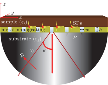
The designed sensor configuration is shown in Fig. 1, which consists of two parts: one is a subwavelength-metal grating (made of silver) deposited on a SiO2 substrate (or base), the other is the sample placed over the grating. The thickness, gap width, and period of the grating are denoted as h, w, and p, respectively. The refractive index is for the substrate and the gap filling, and for the sample. A TM-polarized laser beam (the magnetic field is perpendicular to the xz plane, |E0| = 1) with a wavelength of λ0 = 632.8 nm is incident from the substrate. A two-dimensional finite-difference time-domain (FDTD) method is used to accomplish the simulation. In order to ensure accuracy, the simulated space is meshed into cells with a uniform scale of 1 nm×1 nm. The frequency dispersion of silver is modified by Drude mode as

where the plasmon frequency of ωp = 1.447 × 10¹⁶ rad/s and the collision frequency of Vc = 8.33689 × 10¹³ rad/s are obtained from the best fit of experimental values for the wavelength ranging from 350 nm to 800 nm.[15,16]

Fig. 1. The designed sensor configuration.
3. Results and discussion

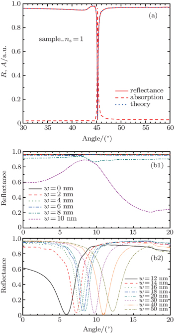
At the very beginning of the studying, the simulation accuracy is evaluated by resorting to the sensor style of Kretschmann for h = 50 nm. In Fig. 2(a), the reflectance (R) is defined as the ratio of total energy flux reflected by the sensor to that of incidence, then the absorption (A) can be calculated by A = 1 − (R + T), where the transmission (T) is defined as the ratio of total energy flux going through the sensor to that of incidence. According to the Kretschmann mode, the resonant incident angle of θ can be obtained by

where

Here, kx represents the incident wave vector projected in x direction, ksp is the wave vector of SPs. Substituting the parameters of ns = 1 and ɛm = −18.3452 into Eq. (2), we find that both the theoretical curves and simulation are matched well as shown in Fig. 2(a). Because the item of ɛm /(ɛs + ɛm) in Eq. (3) is larger than 1, the sensor of Kretschmann requires that the sample’s refractive index is smaller than that of the substrate, or it will fail to work. In Fig. 2(b1) for w = 0 nm, the reflectance keeping a value of 0.95 is produced for ns = 2.0 > ng, which means a challenge for the sensor.

Fig. 2. (a) The sensing properties of Kretschmann for h = 50 nm; (b1) and (b2) the reflectance for ns = 2 at different gap widths.

As the sensor of Kretschmann is confronted with the challenge mentioned above, a feasible way of etching the metal film on it into a subwavelength grating is proposed. For learning its sensing characteristics in depth, the influence of reflectance on the grating’s gap width is studied for p = 260 nm first. In Fig. 2(b1), when a narrow gap is given, one can find that the grating has no contribution to the sensing. With the gradual increase of the gap width shown in Fig. 2(b2), a resonant dip point performance similar to that in Fig. 2(a) is observed, however, the physical mechanisms behind them are different. For the sensor with a grating, the gap serves as a channel. When the gap is tiny enough, its cut-off frequency is too high to stop the incident light coupled by the grating going through it, and while the gap is increased to satisfy with Fabry–Perot (F–P) resonance,[1719] it becomes open for the maximal transmission. In that case, as the increment of the grating thickness goes on, a dip in reflectance curve will emerge periodically. A vivid illustration of F–P resonance is depicted in Fig. 3, where a period changing of reflectance is shown in Fig. 3(a). With the energy flux shown in Fig. 3(b1) for h = 260 nm, from where one can find clearly that the channel offered by the gap to guide the incident light through it is correct, SPs at the grating/sample interface are generated. A phase of Ez is shown in Fig. 3(b2), which is distributed periodically for the interference of gap mode of SPs.[20] For each phase difference of π, as the dashed lines show, the positions of what distributed are consistent with the maximal transmission positions in Figs. 3(b1) and 3(a).
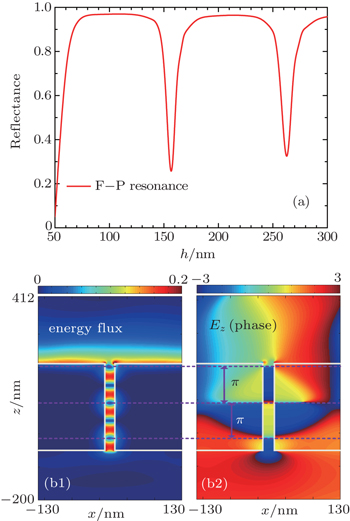
Fig. 3. (a) Reflectance versus the grating thickness h for w = 18 nm, 8.2°; (b1) and (b2) the distribution of energy flux and the phase of Ez for h = 260 nm.

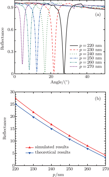
Besides the gap effects, the effects of grating period on reflectance are shown in Fig. 4(a). For one thing, if we estimate the sensing resolution by full width at half maximum (FHWM) of the reflectance curve, except for the influence of gap width on it, which is also influenced by the grating period, the best resolution gives rise to the largest period. For another thing, as the grating period is increased, in response to the dip points emerged in Fig. 4(a), the resonant incident angle is decreased. For the grating with the largest period, that means the amount of gaps etched on it is less. When the light wave goes through the gaps, it will be scattered and absorbed by the gaps to result in energy losses. The less gaps are etched on the grating, the less energy loss is, as a result of it, the best resolution is obtained for the largest period case. In addition, based on the excited SPR theory, it is well known that when a light wave is incident to a metal nanograting, except for kx, an extra wave vector of kg = 2π/p can be provided by the grating. The dispersion relation of kx, kg, and ksp is

when m = −1, equation (4) can be rewritten as

According to Eq. (5), supposing that other parameters are fixed, a conclusion of the smaller incident angle for SPR with the larger grating period is extracted, which agrees well with the phenomenon presented in Fig. 4(a). Furthermore, as we take the theoretical mode ruled by Eq. (5) to compare with the simulation, one can notice them matched well and a reason for the uncertain impacts of grating thickness and the gap on SPR in Eq. (5), they still have some differences between them. Then, a cause of the sharp dip point in reflectance curve for SPR is illustrated.

Fig. 4. (a) Reflectance curves in different grating period p cases; (b) the comparison between the theoretical and simulated results.

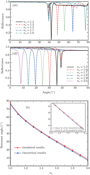
The dip in reflectance curve based on F–P resonance and SPR has been studied successively. Finally, with the optimized parameters of w = 18 nm and p = 260 nm, the sensing properties are discussed. For the reflectance curves shown in Fig. 5(a), there are some phenomena that should be of interest. For the sample with a higher refractive index, in reply to the incident angle, this is the same as the cases of grating period and can also be explained well for SPR by Eq. (5). The next, as seen in the figure, for the improved sensor of Kretschmann, the sensing properties of which are different from those of the traditional one, that is, no matter whether the sample’s refractive index is smaller or larger than the substrate’s, it can always work. We define the sensing sensitivity as

in accordance with the inserted picture in Fig. 5(b), for ns > ng, the resonant angles of incidence are linear to the variation in refractive index of the samples, a sensitivity of S = 51.484°/RIU is acquired, for ns < ng, the sensitivity gets higher than the former. In the end, when a Q factor of

is employed to assess the sensing function, a cause of the widening FHWM, to detect the sample with a high refractive index that is discounted.

Fig. 5. (a1) and (a2) Reflectance curves in different sample refractive index ns cases; (b) the comparison between theoretical and simulated results.
4. Conclusion and perspectives

A subwavelength metal-grating assisted sensor of Kretschmann has been proposed. With the study of the grating’s gap and period effects on reflectance, a cause of the dip point in reflectance curve based on F–P resonance and SPR has been proved. The sensor is able to work when the refractive index of a sample is smaller or higher than that of the substrate. A constant sensing sensitivity of 51.484°/RIU has given rise to the samples with refractive index higher than that of the substrate, and in the lower cases, the value gets higher. Our studies provide a guideline for sensing application based on the subwavelength-metal grating.

Reference
1Kretschmann E 1971 Z. Phys. 241 313
2Raether H1988Surface Plasmons on Smooth and Rough Surfaces and Gratings Vol. 111Berlin, HeidelbergSpringer1133
3Lee BRoh SPark J 2009 Opt. Fiber. Technol. 15 209
4Anker J NHall P WLyandres OShah N CZhao Jvan Duyne R P 2008 Nat. Mater. 7 442
5Jain P KEl-Sayed M A 2010 Chem. Phys. Lett. 487 153
6Hwang G 2009 Nature 457 618
7Salamon ZMacleod H ATollin G 1997 Biochim. Biophys. Acta 1331 131
8Abrantes MMagone M TBoyd L FSchuck P 2001 Anal. Chem. 73 2828
9Kurihara KSuzuki K 2002 Anal. Chem. 74 696
10Kretschmann ERaether H1968Z. Naturforschung. A232135
11Ong B HYuan XTjin S CZhang JNg H M 2006 Sens. Actuators. B 114 1028
12Gupta B DSharma A K 2005 Sens. Actuators. B 107 40
13Chen XJiang K 2010 Opt. Express 18 1105
14Roh SChung TLee B 2011 Sensors 11 1565
15Phan Q HNguyen-Huu NLo Y L 2014 IEEE Sensors. J. 14 2938
16Kawata SOno AVerma P 2008 Nat. Photonics 2 438
17Li X FPan SGuo Y NWang QZhang Y 2010 J. Opt. Soc. Am. B 27 2141
18Guo Y NLi X FPan SWang QWang SWu Y K 2012 Chin. Phys. B 21 057301
19Li X FZhang XGuo Y NMeng JWei J 2013 J. Opt. Soc. Am. B 30 229
20Guo KLiu J LZhou K Y 2015 Chin. Phys. B 24 047301