Wang Shaoyi, Han Dan, Dong Kegong, Wu Yuchi, Tan Fang, Zhu Bin, Fan Quanping, Cao Leifeng, Gu Yuqiu. Single-pinhole diffraction of few-cycle isolated attosecond pulses with a two-color field. Chinese Physics B, 2016, 25(3): 035201
Permissions
Single-pinhole diffraction of few-cycle isolated attosecond pulses with a two-color field
Wang Shaoyi1, Han Dan1, Dong Kegong1, Wu Yuchi1, 2, †, , Tan Fang1, Zhu Bin1, Fan Quanping1, Cao Leifeng1, Gu Yuqiu1, 2
Research Center of Laser Fusion, CAEP, Mianyang 621900, China
IFSA Collaborative Innovation Center, Shanghai Jiao Tong University, Shanghai 200240, China
† Corresponding author. E-mail: ycwu@caep.cn
Project supported by the National Science Instruments Major Project of China (Grant No. 2012YQ130125), the National Natural Science Foundation of China (Grant Nos. 11405159, 11375161, and 11174259), and the Science and Technology on Plasma Physics Laboratory at CAEP (Grant No. 9140C680302130C68242).
Abstract
Abstract
The spatio-temporal characterization of an isolated attosecond pulse is investigated theoretically in a two-color field. Our results show that a few-cycle isolated attosecond pulse with the center wavelength of 16 nm can be generated effectively by adding a weak controlling field. Using the split and delay units, the isolated attosecond pulse can be split to the two same ones, and then single-pinhole diffractive patterns of the two pulses with different delays can be achieved. The diffractive patterns depend severely on the periods of the attosecond pulses, which can be helpful to obtain temporal information of the coherent sources.
With the development of laser technique, the duration of ultrashort intense laser pulse falls continually and has approached two optical cycles, which resulted in a breakthrough of isolated attosecond pulse generation.[1,2] The attoseceond pulse has great potential for controlling and detecting the electronic dynamics of the substance at atom level, such as inner-shell electronic relaxation and ionization by optical tunnelling.[3] Nowadays, various schemes for the attosecond pulse generation, such as Thomson Scattering,[4,5] stimulated Raman scattering,[6] and high-order harmonic generation (HHG)[7–11] have been explored. The HHG is the only experimental way to generate the attosecond pulses.[12–14] The physical mechanism of HHG can be well understood by the three-step model.[15] First, an electron of atoms tunnels through the barrier formed by the laser field and the Coulomb potential, then it oscillates in the continuum, finally it may return to the parent ion, emitting a harmonic photon with maximal energy up to Ip + 3.17Up, where Ip is the ionization potential and is the ponderomotive potential. The first successful method of generating isolated attosecond pulse adopted a few-cycle laser pulse, which only supports 250 as.[3] An alternative method is polarization gating technique,[16,17] the electron in the laser field returns to the parent ion in a short time, which results in the generation of an isolated attosecond pulse. In this scheme, the harmonic yield is very low and the fractional energy of the driving laser pulse is lost. Currently, the two-color field scheme has been proposed to produce an isolated attosecond pulse by manipulating the electron acceleration (acceleration gating, AG) and ionization process (ionization gating, IG).[18–20] Lan et al. found that the isolated attosecond pulse can be obtained in the IG scheme by using the supercontinuous harmonics of the plateau and the harmonic yield is higher than those in the AG scheme.
The study for characterizing the attosecond pulse is at the early stage.[21–23] Due to the lack of nonlinear phenomena in the soft x-ray region for the correlation measurement and the low intensity of attosecond pulses, the atto-correlation scheme is still a challenge.[24–27] The duration measurement of the attosecond pulse is usually performed by the cross-correlation techniques, which only obtains the information of the duration. With the develop of the two-color field schemes and the phase-matching schemes, the yields of the attosecond pulse have improved a lot, which means that it is possible to obtain other temporal information, such as optical periods of attosecond pulse.
In this paper, we investigate that the spatio-temporal characterization of an isolated attosecond pulse in a two-color field. Our results present that a few-cycle isolated attosecond pulse with the center wavelength of 16 nm can be obtained effectively by adding a weak controlling field. Using the split and delay units, the few-cycle attosecond pulse can be split into two same ones,[28] and then single-pinhole diffractive patterns of the two pulses with different delays can be achieved. The diffraction patterns depend severely on the periods of the attosecond pulses, which can be used to temporal diagnostics of the coherent sources.
2. Model and method
In the theoretical model of HHG, the single-atom response (SAR) to the laser field and the collective response in macroscopic gas to high harmonic fields are both taken into account. The single-atom response is calculated with SFA,[29] and the light propagation equations of the laser and HHG are solved in cylindrical coordinate separately in order to simulate the collective response of macroscopic gas.[30]
To simulate the diffraction of the two same attosecond pulse with different delays, we describe two arbitrary attosecond pulses with time delay as[31]
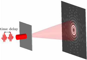
where ϕi(ω) and Ai(ω) are the phase and amplitude of attosecond pulses, respectively. The schematic of the diffraction for the double pules is described in Fig. 1. The two attosecond pulses propagate through a single pinhole with a diameter of 10 μm, and then diffractive patterns can be obtained in the far field. The diffracted field E1Δ(t),r,t after the single pinhole is calculated by
where E0(Δt;r,t) is synthesized by two attosecond pulses with a delay time, T(x,y) is the mask function of the pinhole, z0 is the position of pinhole, and G(r,t;r′,t′) is a propagation function defined as
Fig. 1. Schematic of the single-pinhole diffraction for the attosecond pulses.
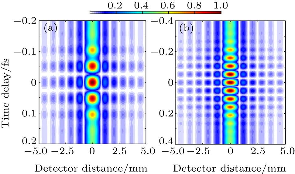
For example, an ideal attosecond pulse with the center wavelength of 20 nm is divided into two same pulses. Figure 2 shows that the diffractive patterns of the attosecond pulses with different periods. The ideal attosecond pulse with five optical cycles in Fig. 2(a) can be split into the two same ones using a split,[32] the delay of the two pulses can be changed by delay units, the results show that the diffractive patterns are a succession of bright and dark areas. Five bright areas appear as the delay of the two pulses varies, which correspond to the isolated attosecond pulse with five optical cycles. For comparison, the diffractive patterns of the attosecond pulse with ten optical cycles are shown in Fig. 2(b), and ten bright areas appear as the delay of the two pulses varies. Figure 2 shows that the temporal information of the attosecond pulse can be obtained from the interference pattern.
Fig. 2. Diffractive pattern of the ideal attosecond pulse with five optical cycles (a) and ten optical cycles (b).
3. Result and discussion
In this work, the two-color laser pulse is synthesized by a 5-fs linearly polarized fundamental field with a wavelength of 800 nm and a 5-fs linearly polarized controlling field with a wavelength of 400 nm. The peak intensity of the fundamental and control fields is 6 × 10¹⁴ W/cm2 and 2.4 × 10¹³ W/cm2, respectively. The electric field of the two-color laser pulse is expressed by
where E1 and E0 are the amplitudes of the control and fundamental fields, respectively; f(t) is the envelope of the laser pulse with a Gaussian shape; ϕ0 is set as 0; and ω0 is the center frequency.
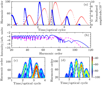
The HHG process in the two-color field is well understood by the semiclassical three-step model and the ADK model which is shown in Fig. 3(a).[32,33] By adding a weak second harmonic laser pulse to the driving field, the two-color field can be modulated, the intensity of the synthesized field is enhanced at 2.5 optical cycle and the intensities of laser pulse at the adjacent half optical cycles are waken. The maximal ionization rate of electrons in the one-color and two-color fields are calculated to be 1.174 × 10⁻⁵ and 0.002772 a.u., respectively. In addition, the ionization rate of the electron within 2.5 optical cycles in the two-color field is much higher than those at other half optical cycles, and then the temporal-spectral characteristics of HHG in the synthesized field show different characteristics with those in one-color case. The underlying physics of the HHG are also understood by the time–frequency distribution, as shown in Fig. 3(c). For comparison, the time–frequency analysis in the fundamental field alone is also shown in Fig. 3(d). For the case of one-color field, there are three dominant peaks obviously in the three half-cycle optical cycles. This means that the harmonic spectrum can be modulated by those three radiation peaks. By adding a weak control pulse, only one dominant radiation peak corresponding to the short and long paths in the two-color case is shown in Fig. 3(c). The other radiation peaks are not obvious due to the low ionization rate. Using the Lewenstein model, the harmonic spectra generated in the two-color field are shown in Fig. 3(b), and the cases in the fundamental pulse alone are also presented. The results show that the regular modulations of high-order harmonic spectra from 20th to 60th in the two-color field appear in the plateau. The harmonic yield is also enhanced by one order.
Fig. 3. (a) Dependence of the harmonic orders on the ionization time (blue asterisk) and recombination time (red dash), and the gray filled curve is the tunnel ionization calculated by the ADK model. (b) High-order harmonic generation in the two-color (blue) and one-color fields (red), corresponding to the time–frequency analysis (c) and (d).
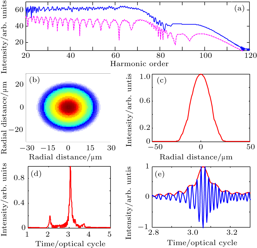
The harmonic spectrum can be further modulated by account of the collective response. The short and long paths have different response in macroscopic gas, which can lead to one quantum path. The nonadiabatic three-dimensional propagation model is performed in a 0.5-mm-long gas target with a density of 1.37 × 1018 cm−3. To optimize the spatial profile of the high-order harmonic spectrum, the driving and controlling pulses foci are placed 2 mm and 0 mm before the gas target, and the beam waists of the driving and controlling pulses are 25 μm and 15 μm, respectively. The other parameters are the same as those in Fig. 3. The spatio-temporal characterization of high-order harmonic generation after propagation in the two-color filed are shown in Fig. 4. When the laser focus is prior to the gas target, the short path can be phase-matched, and the regular modulations of the supercontinuum calculated by the macroscopic response are almost eliminated, a much smoother supercontinuum in the plateau appears, compared with the single-atom response, which is shown in Fig. 4(a). For convenience, the 40th–60th harmonics in the plateau are filtered to generate an attosecond pulse, which is taken as our object of study. The time profile and the oscillating electric field of the isolated attosecond pulse are shown in Figs. 4(d) and 4(e), respectively. The isolated attosecond pulse is obtained by filtering the 40th–60th harmonics in the plateau, and the attosecond pulse duration is about 135 as with five optical cycles. The near-field spatial profile and the spatial image of the few-cycle isolated attosecond pulse are shown in Figs. 4(b) and 4(c), respectively. The phase-matched conditions of the quantum paths and the laser spatial envelope can influence the spatial profile of HHG. Therefore, the spatial profile of the attosecond pulse can be optimized to a Gaussian profile.
Fig. 4. (a) Harmonic spectra after propagation (blue curve) and before propagation (red dashed curve). The spatial image and the near-field spatial profile of attosecond pulse at the exit of the medium are presented. The corresponding time profile and field are also shown in panels (d) and (e).
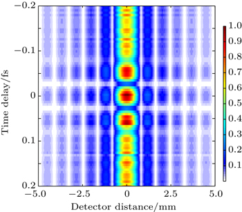
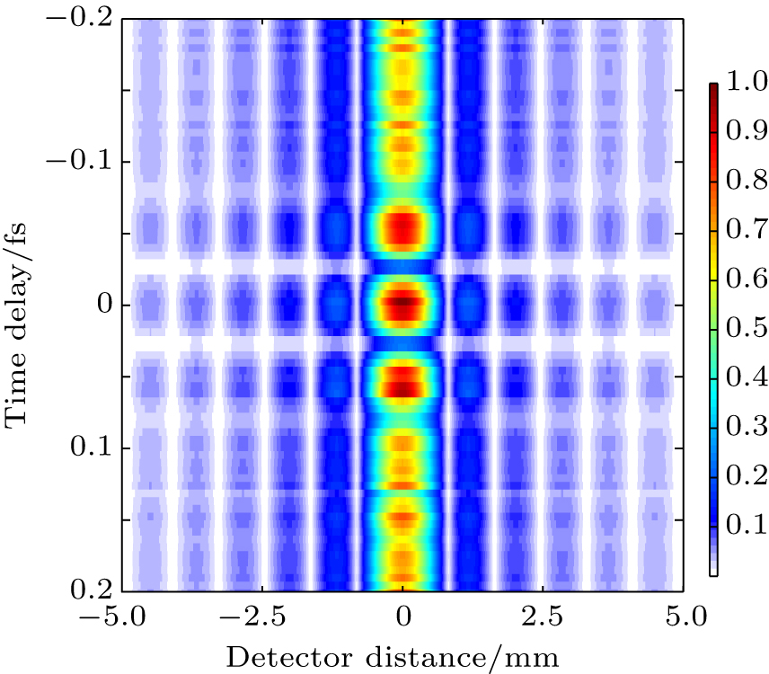
The wavelength of the few-cycle isolated pulse is 16 nm, belonging to the soft x-ray regime. Therefore the optical elements for achieving single-pinhole diffraction of the attosecond pulses have the special optical requirements. Fortunately, to provide the replica attosecond pulses and vary the delay of those pulses, the optical elements such as a beam splitter and pulse delay units have been developed and applied. By using a split optical component, the five-cycle isolated attosecond pulse obtained by the synthesized field is divided into the same two pulses, the delay between the two attosecond pulses can be adjusted by the delay units. The diffraction patterns of the attosecond pulses with different periods are shown in Fig. 5. The delay of the two pulses can be changed, the results show that the diffractive pattern is a succession of bright and dark areas. Compared with those in Fig. 2(a), the patterns obtained by the few-cycle attosecond pulse in the two-color field appear three obvious peaks, while the patterns obtained by the ideal attosecond pulse have five obvious peaks. However, both of the patterns obtained by the two cases have four obvious valleys. Our results show that the temporal information of the isolated attosecond pulse can be obtained from the diffractive pattern.
Fig. 5. Diffractive pattern of the attosecond pulse in the two-color field.
4. Conclusion
In this paper, the spatio-temporal characterization of an isolated attosecond pulse in a two-color laser field is investigated. The results present that a few-cycle isolated attosecond pulse with the center wavelength of 16 nm can be obtained effectively by adding a weak control field, and the intensity of the attosecond pulse is enhance by one order. Using a split unit, the isolated attosecond pulse can be split into the two same ones, and the delay of the two attosecond pulses can be varied by delay units. The single-pinhole diffraction patterns of the two pulses can be achieved by adjusting different delays. The diffraction patterns depend severely on the periods of the attosecond pulses, which can be used in temporal diagnostics of the coherent sources.


 , Tan Fang1, Zhu Bin1, Fan Quanping1, Cao Leifeng1, Gu Yuqiu1, 2]