Flexible impedance and capacitive tensile load Sensor based on CNT composite
Ahmad Zubair1, †, , Karimov Kh S2, 3, Touati Farid1
Department of Electrical Engineering, College of Engineering, Qatar University, Doha 2713, Qatar
Ghulam Ishaq Khan Institute of Engineering Sciences and Technology, Topi, District Swabi, KPK, 23640, Pakistan
Center for Innovative Development of Science and New Technologies, Academy of Sciences, Aini St., 299/2, Dushanbe, 734063, Tajikistan


† Corresponding author. E-mail: zubairtarar@qu.edu.qa

Abstract
Abstract

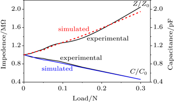
In this paper, the fabrication and investigation of flexible impedance and capacitive tensile load sensors based on carbon nanotube (CNT) composite are reported. On thin rubber substrates, CNTs are deposited from suspension in water and pressed at elevated temperature. It is found that the fabricated load cells are highly sensitive to the applied mechanical force with good repeatability. The increase in impedance of the cells is observed to be 2.0 times while the decrease in the capacitance is found to be 2.1 times as applied force increases up to 0.3 N. The average impedance and capacitive sensitivity of the cell are equal to 3.4 N−1 and 1.8 N−1, respectively. Experimental results are compared with the simulated values, and they show that they are in reasonable agreement with each other.

1. Introduction

Since last decade, nanomaterials have been intensively investigated and used for various electronic sensors. In particular, single-walled carbon nanotubes (SWNTs), double-walled carbon nanotubes (DWNTs), and multi-walled carbon nanotubes (MWNTs) have been investigated for numerous types of sensors.[16] Several studies of carbon nanotube (CNT) applications[711] have proven that they are very favorable for organic electronics due to their flexibilities. For instance, in Ref. [12] it was described that how the miniaturized flexible temperature sensors based on polymer compositions filled with multiwalled carbon nanotubes were successfully fabricated. It was also found that CNTs behave as a semiconductor. The surface-type Al/CNTs/Al flexible temperature sensors have been reported in Ref. [13], where the resistance-temperature relationship has shown semi conductive behavior. The average temperature sensitivity of the sample was found to be (−1.26) %·°C−1. Recently, researchers have also been investigating electromechanical sensors based on CNTs and organic materials composite.[14] In Ref. [15], the recent development in the field of CNT/polymer nanocomposite based strain sensors has been reported. It has been shown that how these sensors are highly sensitive due to the specific conductivities of the composites, in particular, as a result of the presence of the internal conductive network formed by CNTs and tunneling effect of the transfer of charges. It was also shown by Shang et al.[16] that MWNTs and polyurethane can be used for fabricating the elastic conductive nanocomposite. The conductivity of the composite under uniaxial stretch up to 100% did not show significant variation which in turn, is rather unusual for this type of composite. On the other hand, for the case of the devices based on CNT composite, resistive type of sensor is commonly studied. Unlike the resistive sensors, impedance and capacitive sensors exhibit higher stability. In this paper, the fabrication and properties of flexible CNT-rubber composite impedance and capacitive tensile load cells are reported. The aim of this work is to develop a cheep, sensitive and stable tensile sensor using CNTs.

2. Experiment

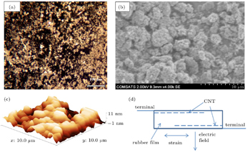
Commercially produced (Sun Nanotech Co Ltd., China) CNT powder was deposited on a thin flexible rubber substrate. The diameter of multi-walled nanotube (MWNT) was in a range of 10 nm–30 nm. The thickness of the commercially available flexible rubber substrate was equal to 80 μm; the dimensions of substrate were around (7 × 5) mm2. Using 5 wt% suspension of the CNT powder in water, the CNTs were deposited on the rubber substrate. Once the CNT film on the rubber substrate dried on one side, then the CNT film was deposited on the opposite side of the substrate. Before deposition of thin film, suspension was stirred for a few minutes. The samples were then pressed at pressures ranging from 4 kN·m−2 to 6 kN·m−2 and temperatures of around 90 °C–110 °C for 1 min–2 min. Figure 1 shows the optical microscope, scanning electron microscope (SEM) and atomic force microscope (AFM) images of the sample of CNT-rubber composite, the schematic diagram of the flexible impedance and capacitive tensile load cell based on CNT-rubber composites. From the microscopic images, it seems that the CNTs have diffused into the rubber substrate to make (composite) rubber imbedded with CNTs. However, from the SEM and AFM images, it can be supposed that the CNT nanoparticles form agglomerates with rubber substrate under the elevated temperature. Figure 1(d) shows the CNT particles diffusion into the rubber substrate to make (composite) rubber imbedded with CNTs.

Fig. 1. (a) Optical microscope image of the sample CNT-rubber composite at 100× magnification, (b) SEM image of the sample CNT-rubber composite, (c) AFM image of the sample CNT-rubber composite (3D view), and (d) schematic diagram of the flexible impedance and capacitive tensile load cell based on CNT- rubber composite.

Figure 2 shows the schematic diagram of the experimental setup for measuring the resistive tensile load cells. On the support 1 the sample 2 was hung. The values of load 3 were changed in the process of the experiment. As contacting electrodes (4 and 5 in Fig. 2) the graphite strips were used. Numbers 6 and 7 represent the wire terminals that are attached to the electrodes by using a silver paste. The AC impedance and capacitance of the samples at 1 kHz were measured by MT 4090 LCR meter. The accuracy of the measurements was around ±2%. The properties of load cells show acceptable stability under the applied load up to 0.3 N.

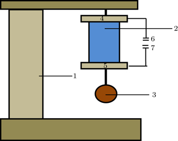
Fig. 2. Schematic diagram of the experimental measurement setup based on the properties of flexible CNTs- rubber resistive tensile load cell, composed of support 1, flexible cell 2, load 3, electrodes (4 and 5), and terminals (6 and 7).
3. Results and discussion

Figure 3(a) shows the impedance-load relationships for the flexible CNTs-rubber tensile load cells. It is seen that impedance monotonically increases as applied load increases. Figure 3(b) shows the capacitance-load relationships for the flexible CNTs-rubber tensile load cells. It has been found that as the load on the device increases, the capacitance value of the sample decreases. The equivalent circuit of the flexible CNTs-rubber composite impedance and capacitive tensile load cell is presented in the inset of Fig. 3. The design of equivalent circuit is based on the fact that the load cell has two conductive layers (plates) separated by a dielectric (rubber). Two plates connected electrically as a capacitor. Each plate acts as a conductive layer that can be considered as a resistor. Therefore, the circuit has two resistors and two capacitors that represent the fact that the load samples are electrically symmetrical from the point of both terminals. The increase of the impedance and decrease of the capacitance of the samples under effect of tensile load can be explained in the way we take into consideration the fact that impedance depends on the resistance and capacitance. As is well known, in a disordered system the transport of charges is observed between randomly distributed sites.[17,18] In hopping, charges hop out from one localized state to another, contributing to conductivity. The conductivity of charges in this random geometry is attributed to percolation theory. According to this theory, the average conductivity of the CNTs-rubber composite can be calculated from this expression σ = 1/LR,[17,18] where L is the characteristic length between sites and R is the average resistance of the connecting path between sites. As load is applied to the sample, due to tensile effect the concentration of charges at sites decreases, as a result the average resistance R between the sites increases and the characteristic length also increases between the neighboring sites. Consequently, the conductivity of overall sample decreases and the resistance of the composite increases, accordingly. Capacitance can be expressed as C = εε0A/d,[19] where ε, ε0, A, and d are permittivity, absolute permittivity, plate area, and distance between plates. Under the applied load, the area of plates decreases and the distance between plates decreases as well. On the other hand, the capacitance can decrease under tensile load due to the decrease of the permittivity of the material. Briefly, it can be explained by the following way. Under the tensile load, the degree of freedom of the molecules or molecular fraction decreases somehow. It can in turn contribute to the decrease of the degree of motion, deviation or rotation of the molecules and its fraction under the effect of external electric field that is applied during the measurement of the capacitance. Thus, as a result, permittivity (of rubber) and capacitance may decrease. Actually under tension (or tensile), the rubber density decreases, which means that numbers of atoms and molecules in the unit of volume decrease. Therefore permittivity decreases and accordingly capacitance decreases under the effect of the load as observed in the experiment. It should be noted that in our experiments the directions of the electric field and strain are perpendicular to each other as shown in Fig. 1(d), similar to the phenomena found in some other materials. For example, the influences of thermal strain on the dielectric constants of barium strontium titanate thin films sputtered on different substrates were observed.[20] Hence, in our case the obtained results can be analyzed thoroughly in future. Detailed discussion about electrical and mechanical phenomena in the load cell will be presented elsewhere.

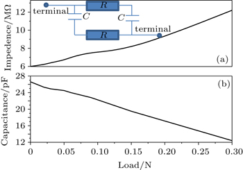
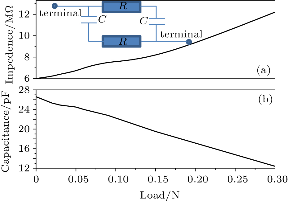
Fig. 3. (a) Impedance–load relationships for the flexible CNTs-rubber tensile load cells. Inset shows the equivalent circuit diagram of the load cell. (b) Capacitance–load relationships for the flexible CNTs-rubber tensile load cells.

As observed in Fig. 3, the impedance-load and the capacitance-load relationships are quasi-linear. By use of the data presented in Fig. 3, the impedance (Sz) and the capacitance (Sc) sensitivities of the cells can be obtained from the following formulas:[21]

where ΔZ/Z0, ΔC/C0, Z0, C0, and F represent the change in impedance, change in capacitance, initial impedance, initial capacitance, and force, respectively. It is found that the values of Sz and Sc are 3.44 N−1 and −1.83 N−1, respectively. The inset in Fig. 3 shows the equivalent circuit diagram of the load cell. The design of equivalent circuit is based on the fact that the load cell has two conductive layers (plates) separated by a dielectric (rubber). Two plates connected electrically as a capacitor. Each plate acts as a conductive layer that can be considered as a resistor. Therefore, the circuit has two resistors and two capacitors that represent the fact that the load samples are electrically symmetrical from the point of both terminals. Figure 4 shows the experimental relative impedance-load and relative capacitance-load relationships for the flexible CNTs-rubber tensile load cells. It is seen that the relationships are quasi-linear. Using a linear function y = kx + b,[22] the following expressions are obtained:

where Z and Z0 are impedances and C and C0 capacitances of the samples under load (p) and at the initial states; k1 and k2 are fitting parameters. For the values of k1 = 3.2 N−1 and k2 = (−1.8) N−1, the simulated graphs are shown in Fig. 4. Equations (3) and (4) are corresponding to the experimental results given in Fig. 3. The capacitance and resistance show almost linear response as a function of applied load. Using a linear function y = kx + b, equations (3) and (4) describe the behavior of the sensor as a function of applied load. It is seen that the simulated graphs in the first approximation are consistent with experimental results. The expressions (1) and (2) presented above represent the sensitivities Sz and Sc of the load cell. Sz and Sc play the same role as gauge factor (GF) in the strain sensor. Gauge factor is defined as GF = (ΔR/RG)/ε,[23] where ΔR is the change in resistance caused by strain, RG is the resistance of the undeformed gauge, and ε is the strain. Analogously for this load cell it can be determined that gauge factors for impedance (Z)-strain and capacitance (C)-strain relationships are GF(Z) = (ΔZ/Z)/ε and GF(C) = (ΔC/C)/ε, respectively. Their values are found to be GF(Z) = 2.0 and GF(C) = −1.1. It should be important to mention that the resistance of the cells is very large (out of measurement range of the LCR meter), therefore it is more suitable to measure impedance and capacitance.

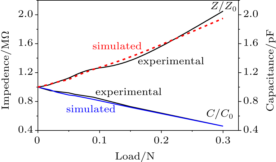
Fig. 4. Experimental and simulated curves of the relative impedance and relative capacitance.

In the study by Yasuoka et al.,[24] the employment of carbon nanofiber (CNF) and elastomer composite as resistive strain gauge sensing device has shown a promising potential due to its decent flexibility, and conductivity. The device is sensitive enough and exceeds the conventional measurement limit of 40% strain deformation. Besides, it can offer wider applications due to the virtue of its flexibility thus it is much favorable for measuring flexible materials. Meanwhile, Manandhar et al.,[25] have reported the application of wet hydrogel based strain gauge which can measure up to 25% of strain, and its gauge factor was found to be near 2. The presence of carbon filling and conducting polymer coating further enhances the sensing performance, so that it exhibits no relaxation nor hysteresis effect. However, still, it encounters some problems such as the drifting effect which could be avoided only through proper encapsulation and installation of the electrical wiring connection due to the soft nature of the aerogel. A study to investigate the flexible large strain gauge sensor from polypyrrole on rubber substrate was carried out by Tjahyono et al.[26] The sensor was reported to have good stability and consistency, with a gauge factor of 1.86. The consistency of the device is associated with the careful control of the extension and contraction of the air muscle with a PID controller. On the other hand, a simple, flexible, and highly sensitive strain gauge sensor was developed by Pang et al..[27] through using a method of reversible interlocking of nanofibers. The sensor is sensitive enough to detect changes in pressure, shear, and torsion force with gauge factors of 11.5, 0.75, and 8.53 respectively. These properties, thus, make it have potential applications such as artificial skin attachable sensor. The sensor also has a highly repeatable response of up to 104 cycles, and excellent switching characteristics. In comparison, we report on the fabrication and investigation of flexible capacitive and resistive mechanical sensing device based on carbon nanotube (CNT) composite. The device has shown good sensitivity and good repeatability in response to the applied force of up to 0.3 N. The changes in both impedance and capacitance are measured to be factors of 2.0 and 2.1 with gauge factors of 2.0 and −1.1, respectively.

4. Conclusions

The investigation of the properties of the flexible impedance and capacitive tensile load cells based on CNT composites shows that the cells are very sensitive to the force and has good repeatability. The impedance of the cells is observed to increase 2.0 times on average and the capacitance decreases 2.1 times by increasing the force up to 0.3 N. The experimental results are compared with the simulated ones, showing that they are in reasonable consistence with each other. The decrease of the conduction of the CNT-rubber composite under the effect of the tensile load is explained by percolation theory. The decrease of the capacitance of the sample under the effect of the tensile force is also explained by the possible decrease of dielectric permittivity of the CNT-rubber composite under the effect of the strain.

Reference
1Cantalini CValentini LArmentano ILozzi LKenny JSantucci S 2003 Sensors Actuators B: Chem. 95 195
2Na P SKim HSo H MKong K JChang HRyu B HChoi YLee J OKim B KKim J J 2005 Appl. Phys. Lett. 87 093101
3Rinkiö M Zavodchikova M Y Törmä P Johansson A 2008 Physica Status Solidi (b) 245 2315
4Saleem M Karimov K S Karieva Z Mateen A 2010 Physica E: Low-dimensional Systems and Nanostructures 43 28
5Tang D Kim N Ci L Zhou W Xie S 2006 Carbon 44 2155
6Varghese OKichambre PGong DOng KDickey EGrimes C 2001 Sensors and Actuators B: Chemical 81 32
7Billinghurst MStarner T1999Computer3257
8Paradiso RGemignani AScilingo EDe Rossi D2003Knitted bioclothes for cardiopulmonary monitoringIEEE, 3720
9Park SJayaraman S 2003 IEEE Engineering in Medicine and Biology Magazine 22 41
10Rossi D DLorussi FMazzoldi AOrsini PScilingo E P2003Active Dressware: Wearable Kinesthetic Systems. in Sensors and sensing in biology and engineeringBarth Friedrich GHumphrey Joseph A CSecomb Timothy W Wien, New YorkSpringer-Verlag
11Service R F 2003 Science 301 909
12Sibinski MJakubowska MSloma M 2010 Sensors 10 7934
13Karimov K SKhalid F ATariq Saeed Chani MMateen AAsif Hussain MMaqbool A2012OAM-RC6194
14Karimov K SAbid M2011Organic Semiconductor Electromechanical Sensors. Pressure, Displacement and Strain Sensors(VDM Verlag Dr. Muller GmbH & Co. KG Dudweiler Landstr, 99, 66123 Saarbrucken, Deutschland)
15Hu NFukunaga HAtobe SLiu YLi J 2011 Sensors 11 10691
16Shang SZeng WTao X M 2011 Journal of Materials Chemistry 21 7274
17Brabec C J2003Organic photovoltaics: concepts and realizationBerlinSpringer10.1039/c0cs00045k
18Böttger HBryksin V V1985Hopping conduction in solidsWeinheimVCH
19Yavorsky BDetlaf A1980Handbook of physicsMir
20Taylor THansen PAcikel BPervez NYork RStreiffer SSpeck J 2002 Appl. Phys. Lett. 80 1978
21Riley W FMcConnell K GDally J WDally J WDally J W1993Instrumentation for engineering measurementsWiley
22Croft ADavison RHargreaves M1992Engineering Mathematics: A Modern Foundation for Electrical, Electronic, and Control EngineersAddison-Wesley Longman Publishing Co., Inc.
23Riley W F McConnell K G Dally J W1993Instrumentation for engineering measurementsJohn Wiley & Sons, Inc
24Yasuoka TShimamura YTodoroki A 2013 International Journal of Aeronautical and Space Sciences 14 146
25Manandhar PCalvert P DBuck J R 2012 IEEE Sensors Journal 12 2052
26Tjahyono A PAw K CTravas-Sejdic J2012Sensors and Actuators B: Chemical166426
27Pang CLee G YKim TiKim S MKim H NAhn S HSuh K Y 2012 Nat. Mater. 11 795