


Development of a new correlation to calculate permeability for flows with high Knudsen number
[Dehdashti Esmaeil†,  ]
]
]
|
|


† Corresponding author. E-mail:
Flows with high Knudsen number play a prominent role in many engineering applications. The present study is an effort toward the simulation of flow with high Knudsen number using modified lattice Boltzmann method (LBM) through a porous medium in a channel. The effect of collision between molecules and solid walls, which is required to accurately simulate transition flow regime, is taken into account using a modified relaxation time. Slip velocity on the wall, which is another significant difficulty in simulating transition flow regime, is captured using the slip reflection boundary condition (SRBC). The geometry of porous medium is considered as in-line and staggered. The results are in good agreement with previous works. A new correlation is obtained between permeability, Knudsen number and porosity for flows in transition flow regimes.
Due to the recent rapid development of micro flow devices applied in micro-total-analysis-systems (m-TAS) and micro-electro-mechanical systems (MEMS),[1–5] modeling and simulation methods for flows in such micro geometries have been of great interest in the society of computational physics.[6–8] In many mathematical models of important phenomena with real-life applications, one faces the challenge of spatial scales. This is true in particular in the study of flow and transport in porous media, which is important in environmental studies, geophysics, reservoir engineering, and medicine.
Flow through the porous medium has become one of the most significant research subjects in many science and engineering fields because of its wide spectrum of applications. In particular, the prediction of macroscopic or effective transport properties has been considered as a fundamental and practical problem.[9] Advances in micromachining technology have spawned many opportunities to precisely fabricate mechanical devices of micron size such as channels, nozzles, and so forth.
The Navier–Stokes (macroscopic momentum) equations are, no longer applicable to flows with high Knudsen number and the physics of flow in such flows is described by the Boltzmann equation (BE) of the gas kinetic theory.[10] For example, problems such as multiphase flows,[11] turbulent flow,[12,13] flows considering fluid–solid interaction (FSI),[14] and thermal flow[15] could be handled effectively using the LBM. For Kn < 10−3 the continuity assumption with no slip boundary conditions is valid. For 10−3 < Kn < 10−1 (slip flow regime) the velocity and temperature of the gas near the wall are no longer equal to the wall velocity and temperature respectively and for Kn > 10−1 (transition and free molecular flow regime) the continuity assumption is under question.[6] For the transition regime (Kn > 10−1), the continuity assumption and consequently the validity of the Navier–Stokes equations, NSE, is questionable as the size is reduced significantly. In such cases, because of the solid walls effect, the fluid flow behavior depends strongly on the geometry dimensions.[6]
Recently there have been efforts to employ the LBM for flows with high Knudsen number in slip flow regime[16–22] but only a few papers can be mentioned for the use of LBM in transition regime.[23–29] To this end, two methods are proposed based on the use of higher order LBM[23–26] and the modification of the mean free path.[26–29] The multi-speed or higher order LBM has been developed to increase the order of accuracy in the discretization of velocity phase space. Although Ansumali, et al.[25] have demonstrated that the high-order LBMs have improved current capability, Kim et al.[26] showed that this method can predict the rarefaction effects only for Kn = O(0.1) and at large Kn, the mass flow rate cannot be predicted properly by these methods. Additionally, the high-order LBMs with large numbers of discrete velocities are not numerically stable.[30] One of the problems which happens in the high Kn number flow in a channel is that velocity profiles of flow in the transition and free molecular regimes remain approximately parabolic. But the velocity profile obtained from continuum-based relations does not predict the flow rate properly.[6] This is due to the fact that the dynamic viscosity must be modified to consider the diffusion of momentum because of the intermolecular collisions and the collision of molecules with the walls in comparison to considering the diffusion of momentum because of the intermolecular collisions alone. In the transition regime, intermolecular collisions and molecule–wall collisions have the same order, while in the free molecular regime, the molecule–wall collisions are the dominant phenomenon. However, to the best of our knowledge, there were few efforts to study and find a correlation between permeability, porosity, and Knudsen number in the transition regime.
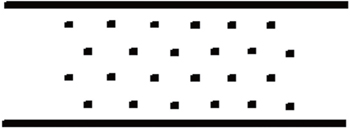
In the present study, we first simulate flows through a channel with low Knudsen number. A porous medium, which is considered as in-line and staggered, is placed through the channel. A schematic picture of two kinds of geometry is shown in Fig.
 | Fig. 1. Solution domain including porous medium with in-line geometry. |
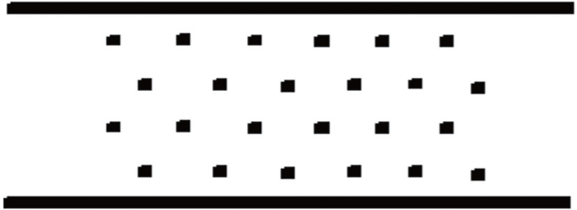 | Fig. 2. Solution domain including porous medium with staggered geometry. |
The rest of this paper is organized in the following way. The formulations for LBM are presented in Section 2. Thereafter, the modification required to solve flow with high Kn number is explained in Section 3. In Section 4, boundary conditions are presented. The results and respective discussions are given in Section 5. The conclusion and the future works which can be done as a continuation of this work are presented in Section 6.
The LBM originated from lattice gas (LG) automata,[31] which are discrete particle kinetics based on discrete time and lattice spaces. The LB equation is expressed as:

In Eq. (
For the BGK model,[32] the collision operator is expressed as:


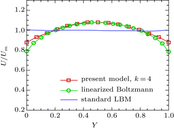
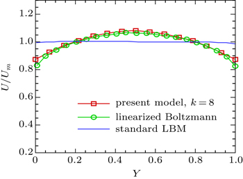
It is found out from the direct simulation Monte Carlo (DSMC) method and linearized Boltzmann equation[33] that velocity profiles in a channel in transition and free molecular regimes remain roughly parabolic. But the velocity profile which is obtained from relations based on continuum assumption does not predict the flow rate properly.[6] This is due to the fact that any discrete velocity model describes a whole set of molecular speeds within a finite solid angle, by a single discrete speed. Although the reduction of degrees of freedom leads to a very efficient scheme, it causes the particles, which in fact collide with the wall, moving parallel to it and make an unrealistic free-acceleration regime due to the effect of pressure gradients or body forces within the fluid flow.[34] Therefore, a general form of the effective viscosity as a function of the Knudsen number has been proposed,[6] which is valid for a wide range of flow regimes


In the present work, since flow with high Kn number is simulated, it is required to apply a boundary condition on solid walls to be capable of predicting the slip velocity on solid walls. The boundary condition which is applied to fulfill the required conditions on solid walls is the slip reflection boundary condition (SRBC),[37] which is a combination of the bounce back and specular boundary conditions. For example, at the lower boundaries, the unknown particle distribution functions f2, f5, and f6, can be calculated as follows:
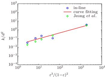
In the present study, two-dimensional flow in a channel is solved. Moreover, there is a porous medium, which is considered in-line and staggered, through the channel. In this section, non-dimensional permeability (k/d2) is calculated in different conditions including different Kn and porosity (ϵ). To validate the results, flow with low Kn is simulated, then we extend high Kn and a new correlation is derived for transition flow regime.
First, the flow with low Kn number is solved in a channel. The results are compared to the those of Jeong et al.[9] for low Kn number. Our study shows that for low Kn number, changes of Kn number do not have a noticeable influence on the results.
Figures
 | Fig. 3. Non-dimensional permeability versus porosity for in-line geometry. |
 | Fig. 4. Non-dimensional permeability versus porosity for staggered geometry. |
 | Fig. 5. Velocity profile for flow through a channel at K which is defined as  |
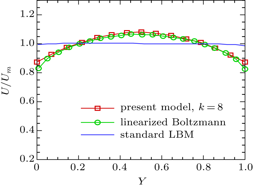 | Fig. 6. Velocity profile for flow through a channel at K which is defined as  |
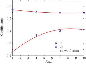
After validating the boundary condition and the relaxation time, flow with high Kn number through a channel through which a porous medium placed is solved. The investigations show that non-dimensional permeability depends on porosity and Kn number. So, the following simulations will be performed to achieve a new correlation between k/d2, ϵ, and Kn. First, as shown in Fig.

| Table 1. A and B for flows with different Kn numbers in a channel through which an in-line porous medium is placed. . |
| Table 2. The amounts of C1, C2, and C3 for flow in a channel through which an in-line porous medium is placed. . |
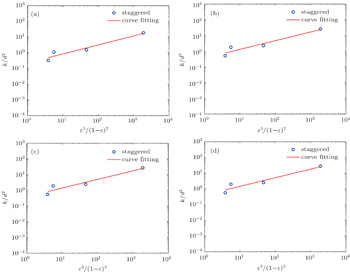
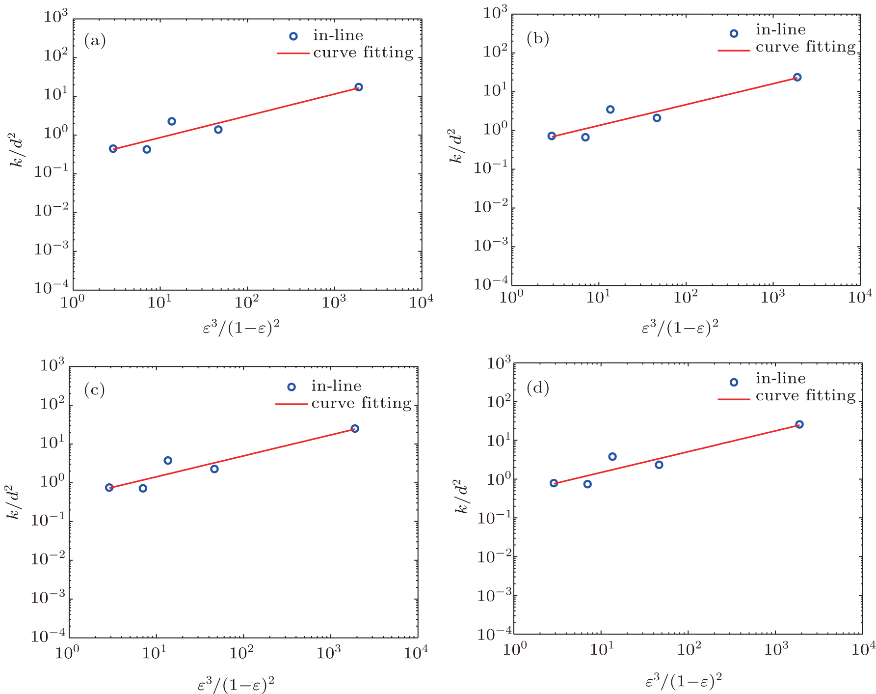 | Fig. 7. Non-dimensional permeability versus porosity for in-line geometry and different Kn number: (a) Kn = 1, (b) Kn = 4, (c) Kn = 7, and (d) Kn = 10. |
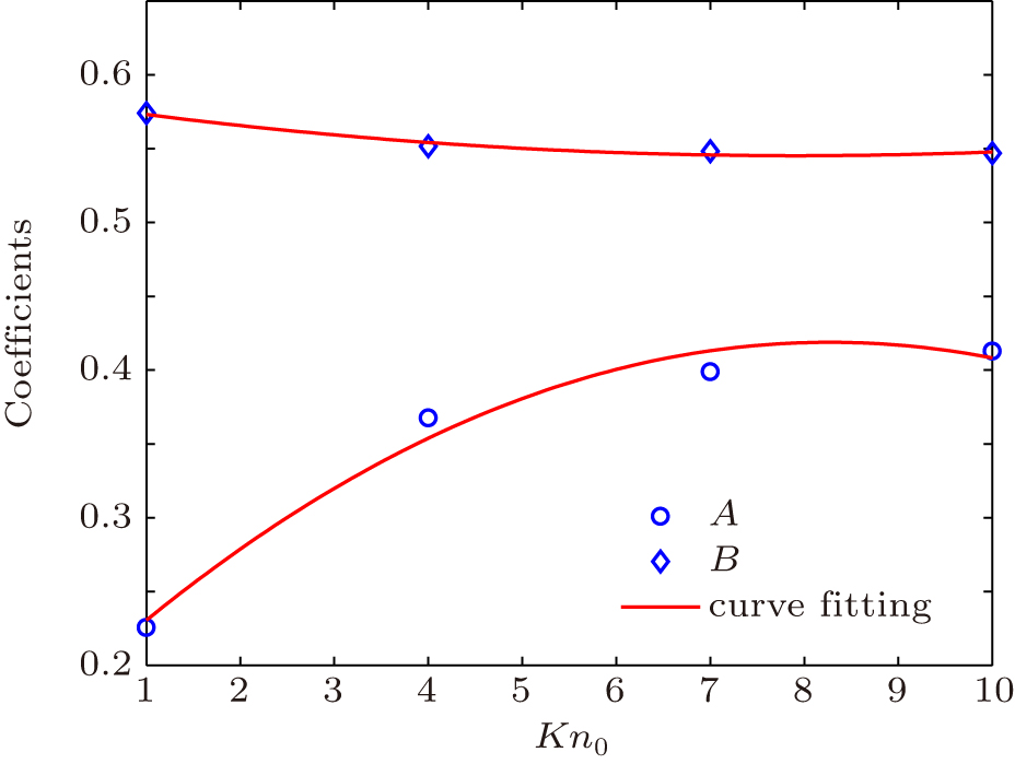 | Fig. 8. A and B for flows with different Kn numbers in a channel through which an in-line porous medium is placed. |
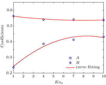
Now that the results are shown for in-line porous medium, those for a staggered porous medium are shown in the following to assess whether or not geometry of porous medium has a significant influence on results. Hence, we investigate the flow in a channel through which a staggered porous medium is placed. The results are shown in Fig.
| Table 3. A and B for flows with different Kn numbers in a channel through which a staggered porous medium is placed. . |
| Table 4. The amounts of C1, C2, and C3 for flow in a channel through which a staggered porous medium is placed. . |
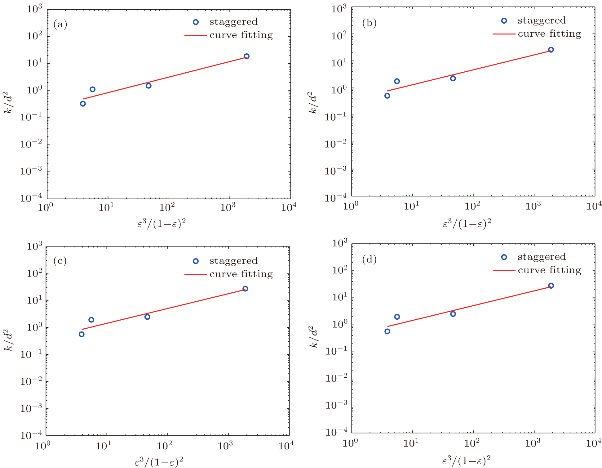 | Fig. 9. Non-dimensional permeability versus porosity for staggered geometry and different Kn number: (a) Kn = 1, (b) Kn = 4, (c) Kn = 7, and (d) Kn = 10. |
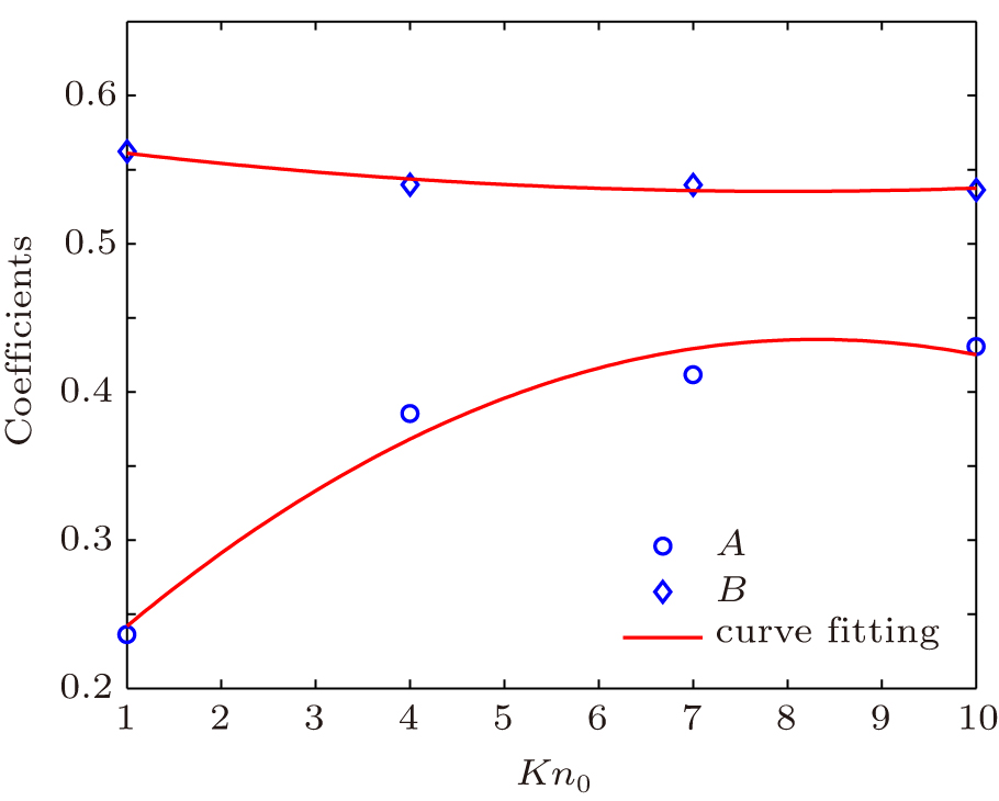 | Fig. 10. A and B for flows with different Kn numbers in a channel through which a staggered porous medium is placed. |
In the present study, flow was solved in a channel in which a porous medium exists. Results are presented for both in-line and staggered geometries of the porous medium. Since changes of porosity and Kn number do not influence the non-dimensional permeability of flow with low Kn number, the results are presented for a single Kn number. Thereafter, simulation was extended to flow with high Kn number up to 10. SRBC was employed to capture slip velocity on the walls in flow with high Kn number. Moreover, an appropriate relaxation time was applied to simulate rarefied flows. The results show that the non-dimensional permeability is strongly dependent on porosity and Kn number in flow with high Kn number. Since it was also illustrated that non-dimensional permeability is not strongly dependent on geometry of porous medium, a correlation was derived between non-dimensional permeability, porosity, and Kn number. Nonetheless, the correlation was obtained for in-line and staggered geometry. The present study is a promising work to calculate permeability as a function of porosity and Kn number. This work can be seminal to future research on understanding and developing new methods to study rarefied flows. Also, the present work can be extended to more complex problems such as FSI, flow in a more complex geometry and so forth.
| 1 | |
| 2 | |
| 3 | |
| 4 | |
| 5 | |
| 6 | |
| 7 | |
| 8 | |
| 9 | |
| 10 | |
| 11 | |
| 12 | |
| 13 | |
| 14 | |
| 15 | |
| 16 | |
| 17 | |
| 18 | |
| 19 | |
| 20 | |
| 21 | |
| 22 | |
| 23 | |
| 24 | |
| 25 | |
| 26 | |
| 27 | |
| 28 | |
| 29 | |
| 30 | |
| 31 | |
| 32 | |
| 33 | |
| 34 | |
| 35 | |
| 36 | |
| 37 |