† Corresponding author. E-mail:
Project supported by the National Magnetic Confinement Fusion Science Program of China (Grant Nos. 2011GB102000, 2012GB103000, and 2013GB106001), the National Natural Science Foundation of China (Grant Nos. 11175206 and 11305211), the JSPS-NRF-NSFC A3 Foresight Program in the Field of Plasma Physics (Grant No. 11261140328), and the Fundamental Research Funds for the Central Universities of China (Grant No. JZ2015HGBZ0472).
The optimized synergy conditions between electron cyclotron current drive (ECCD) and lower hybrid current drive (LHCD) with normal parameters of the EAST tokamak are studied by using the C3PO/LUKE code based on the understanding of the synergy mechanisms so as to obtain a higher synergistic current and provide theoretical reference for the synergistic effect in the EAST experiment. The dependences of the synergistic effect on the parameters of two waves (lower hybrid wave (LHW) and electron cyclotron wave (ECW)), including the radial position of the power deposition, the power value of the LH and EC waves, and the parallel refractive indices of the LHW ( N ∥ ) are presented and discussed.
Both the lower hybrid current drive (LHCD) and electron cyclotron current drive (ECCD), as two important ways of non-inductive current drive in tokamak, have advantages and disadvantages. The greatest advantage of LHCD is the high current drive efficiency, because it can directly increase the parallel velocity of current-carrying electrons through Landau damping. Its main drawbacks are difficulty of current profile control and accessibility problem at high density. Compared with LHCD, the ECCD is widely used to control the plasma current profile and suppress the plasma MHD activity due to easy coupling, strong localization, and controllable absorption. However, the disadvantage of the ECCD is the low current drive efficiency, because it is drive current indirectly through cyclotron damping which causes resonant electrons to obtain energy and an increase of the perpendicular velocity.
Owing to these complementary features, a combination of LHCD and ECCD becomes an appealing solution for high-performance and long-pulse advanced tokamak discharges. Fidone first proposed in the 1980’s [ 1 ] that the I EC+LH , which is defined as the total current driven by the ECW and LHW simultaneously, is larger than the sum ( I EC + I LH ) of the currents driven by the ECW and LHW separately, i.e., I EC+LH > I EC + I LH . Since then, theoretical and experimental studies of the synergy have been carried out in many devices, such as WT-2, [ 2 ] JFT-2M, [ 3 ] WT-3, [ 4 ] Versator II, [ 5 ] etc. In addition, several Fokker–Planck codes [ 6 – 8 ] have numerically demonstrated this phenomenon. However, the results of these experiments could not provide a quantitative assessment of the synergistic effect. In 2004, the first experimental verification of the synergy between LHCD and ECCD was obtained on Tore Supra, [ 9 ] and this experiment still needs further physical explanation. Therefore, it is necessary to study the physical mechanism of the synergistic effect, which will provide a theoretical direction, and the optimized synergy conditions for the synergy experiments will be carried out on the EAST.
At present, it is considered that the synergistic effect is caused by the synergy electrons arising from the two waves in the phase space. [ 10 ] The so-called synergy electrons are those high-energy electrons, each of which obtains a higher vertical velocity u ⊥ and parallel velocity u ∥ by interacting with ECW (or LHW), and thus enters the LHW (or ECW) resonant region. The current driven by these high-energy electrons is the additional synergy current generated during the synergy period. It is generally considered that there are two mechanisms of the synergetic effect: (i) the electrons are first pushed by the ECCD, and then be further driven by the LHW as long as they enter the LHCD resonant region; and (ii) the electrons are first dragged by the LHCD, and then the ECW could selectively couple with the fast electron tail sustained by the LHW.
The codes used to obtain LH+EC wave absorption and LH+EC synergy current are GENRAY [ 11 ] /CQL3D, [ 7 ] FRTC [ 12 ] /OGRAY [ 8 ] and C3PO [ 13 ] /LUKE. [ 6 ] In this study, the C3PO/LUKE code is used. The LUKE is a code for solving the three-dimensional (3D) (two-dimensional (2D) momentum and one-dimensional (1D) radial) bounce-averaged relativistic electron drift kinetic equation for the absorption of the waves by the electrons, which is coupled to the ray-tracing solvers C3PO for the wave propagation. It is designed for the current drive problem of any RF electron wave (LH, EC, electron Bernstein waves) in tokamak with an arbitrary axisymmetric magnetic equilibrium. The C3PO/LUKE code can be used to simulate ECRH/ECCD, as well as synergistic effects with other electron waves such as LHCD in a consistent way.
In the following, we discuss the kinetic modeling of LH+EC current drive. Current drive by superthermal electrons is numerically investigated using the 3D linearized relativistic bounce-averaged electron Fokker-Planck equation: [ 6 , 14 , 15 ]


The flux divergences of the momentum and radial space in the kinetic equation (


The superscript “(0)” represents the bounce averaged, λ is the normalized bounce time, and S T is the electronic radial diffusion transport (T) induced electron flux.
The phase space flux S (0) is decomposed into a diffusive term and a convective term, i.e., S (0) = − D (0) ∇ f (0) + F (0) f (0) . Here, D (0) and F (0) are respectively the diffusion tensor and convection vector in phase space. The bounce averaged flux of Eqs. (


These coefficients 


For the RF wave terms (LH, EC), corresponding diffusion tensors which depend on the waves present in the plasma and are based on the quasilinear theory of the interactions between waves and plasmas can be expressed as follows:


Here, 
The detailed expressions of other coefficients for different physical terms (C, E, and T) can be found in Ref. [ 6 ].
The current density carried by electrons associated with f can be calculated by

The RF power absorbed per unit volume by the plasma is given by

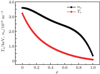
EAST is a full superconducting tokamak device with non-circular cross section. The typical background plasma parameters are as follows: plasma major radius R = 1.85 m, plasma minor radius a = 0.45 m, plasma elongation ratio κ = 1.9, and triangle variable factor δ = 0.5. The working frequency of the ECRH system is chosen to be 140 GHz and the second harmonic extraordinary mode (X2) is used for electron heating and current drive. The wave source is amplified by 4 gyrotrons each with 1 MW/100 s output power. A total power of 4 MW is injected into the plasma through the horizontal port from the low field side. The radius of the launch point of the EC wave R a is 300 cm, and the vertical deviation of the launch point with respect to the middle plane Z a is 30 cm.
In order to compare with the experimental results better, the parameters adopted in this calculation are given as plasma current I P = 400 kA, toroidal magnetic field Bt 0 = 2.3 T, lower hybrid wave (LHW) frequency f LH = 4.6 GHz, LHW power P LH = 2 MW, and the peak value of parallel refractive index 
In order to investigate the effect of radial position of the power deposition on the synergistic effect between ECCD and LHCD, the radial position of the peak drive current density of the LHW is fixed to be ρ LH = 0.05. At the same time, a movable mirror is used to adjust the toroidal or poloidal incident angle of the EC wave antenna, hence changing the radial position of ECW power deposition. The synergistic effects at different values of radial position ρ EC (in normalized radius) at which the EC current is driven are investigated by scanning the poloidal injection angle θ and toroidal injection angle φ of ECW. The calculation results are shown in Fig.
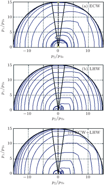
In order to obtain a larger synergistic effect, the first condition is to make the peaks of the drive current density of the LHW and ECW overlap. Furthermore, the diffusion regions of the two waves in the velocity space must also overlap. Figure
The electron distribution functions before and after inputting the EC or LH waves [ 17 ] are shown in Fig.
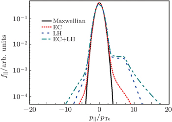 | Fig. 4. Parallel distribution functions with Maxwellian, ECW only, LHW only, and ECW+LHW at ρ = 0.05. |
In conclusion, there is a strong dependence of the synergistic effect between LHCD and ECCD on the power deposition locations of the two waves. A larger synergistic effect could be obtained when the peaks of the ECW and LHW current density are superposed, because this may further make the two waves overlap in the velocity space, and the overlapping of the diffusion regions of ECW and LHW can make the high-energy electrons accelerated by one kind of wave accelerate, and further by another wave, and then an additional synergistic current can be formed effectively. The power deposition position of the LHW is mainly determined by LHW power spectrum, profiles of plasma temperature and density, which are generally difficult to adjust. However, the change of the location of the ECW can be easily realized by adjusting the toroidal and poloidal incident angle of the ECW antenna. Therefore, in order to obtain a better synergistic effect, the ECW power is arranged to deposit at the same radial position of the LHW power by selecting appropriate toroidal and poloidal inject angles of the ECW. The relationships between the ECW parameters and its deposition position have been studied in detail in Ref. [ 18 ].
The relationship between the synergistic effect and the powers of ECW and LHW has been studied numerically and experimentally in many fusion devices. Research shows that the fraction of the trapped electrons, the changes of the local temperature, [ 7 ] the profile of the wave power deposition and its absorption position [ 19 ] are affected strongly by the levels of the powers of the two waves, which make the synergy current change, even lower than zero, i.e., a negative synergy effect ( I EC+LH < I EC + I LH ) can be obtained when the ratio between the powers of the two waves satisfies a certain condition. [ 20 , 21 ] Therefore, it is necessary to study the dependences of the synergistic effect on ECW power and LHW power in the EAST to avoid the negative synergy effect, which is meaningful for guiding the relevant physical experiments in the future.
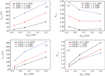
The synergy currents are investigated with the LHW and ECW power scanning from 0.5–2 MW, respectively. The calculation results are shown in Fig.
The mechanism of current enhancement caused by the synergy of two waves can be qualitatively explained as follows. [ 22 ] First, the application of ECW leads to the increase of the fast electron population, and the effect of Landau damping of the LHW is improved. Then the local electron temperature increases because of the ECW, which will reduce the collision frequency between the resonant electrons and background ions (the collision frequency is proportional to 
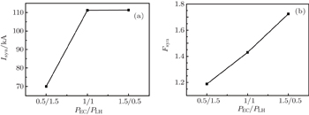
Figure
The parallel refractive index of LHW ( N ∥ ) is an important parameter for LHCD, which determines the properties of the LHCD experiment, such as the coupling of the wave to the plasma, the propagation of the LHW, the LHW power deposition, the driven current profile, as well as the current drive efficiency, and then will affect the synergistic effect simultaneously.
In order to study the dependence of the synergistic effect on N ∥ of the LHW on the EAST, the comparisons of the synergistic effect among three cases of 


The resonant condition of the LHW, according to ω − k ∥ v ∥ = 0, [ 23 ] where ω is the LHW frequency, v ∥ and k ∥ = N ∥ ω / c are the parallel components of the velocity of the resonant electrons and wave vector of the LHW, respectively, can be written in the form of

On the other hand, N ∥ of the LHW determines the resonance and position of the LHW, then it will affect the production of the synergy electrons. Figure
In a word, the synergistic effect is better when the LHW with an appropriate N ∥ that can drive a larger current and can make the resonance area of the two waves in the velocity space overlap combines with the ECW.
Numerical simulation of the synergistic effect between LHCD and ECCD is systematically done and investigated by C3PO/LUKE in EAST tokamak. By simulation, we study the dependence of the synergistic effect on the power deposition locations of ECCD and LHCD, the power level of the two waves, and the parallel refractive indices of the LHW. In order to obtain a better synergistic effect, the peaks of the drive current density of the LHW and ECW must be overlapped, because this may further make the diffusion region of two waves overlap in the velocity space. We usually adjust the poloidal or toroidal incident angle of the ECW to deposit the ECW power at the same radial position of the LHW to obtain a good synergistic effect. Furthermore, the synergistic effect is much more dependent on the levels of EC and LH wave power. Moreover, as the powers of the two waves increase, the synergy currents vary linearly with the LHW and ECW power at the power levels of 0.5–2 MW on the EAST, the maximum total current driven by the ECW and LHW simultaneously and synergy current calculated by the C3PO/LUKE code on EAST are about I EC+LH = 830 kA and I syn = 300 kA with P LH = 2 MW and P EC = 2 MW, respectively. However, in this paper we neglect the change of the electron temperature T e profile (and the density). While in the real experiment, the plasma temperature and density change with the values of LHW and ECW power, which can also affect the influence of the tail of the distribution function of the electrons on the synergistic effect. Finally, since LHCD current and the resonant position are significantly affected by N ∥ , an important parameter for the synergistic effect.
Note that the present simulation is preliminary and to investigate the synergy effect for a given LH power deposition by modifying EC wave parameters so as to gain a large driven current. Such simulation results depend on LH power deposition, which is related to the LH model, e.g., effects of spectrum broadening on power deposition. In this paper, we only consider the case of power deposition with the LH model without considering spectrum broadening. In addition, note that high power injection (e.g., 4 MW) will strongly modify the plasma, and radial transport may totally cancel the effects if anomalous transport is too high. The tail of the distribution function of the electrons cannot be built, and the synergy will drop. Therefore, the role of power scanning is only to see the change tendency of the synergy effect. Further work will be performed by comparing experiments and LH simulation where a more reasonable LH model is applied.
| 1 | |
| 2 | |
| 3 | |
| 4 | |
| 5 | |
| 6 | |
| 7 | |
| 8 | |
| 9 | |
| 10 | |
| 11 | |
| 12 | |
| 13 | |
| 14 | |
| 15 | |
| 16 | |
| 17 | |
| 18 | |
| 19 | |
| 20 | |
| 21 | |
| 22 | |
| 23 |


