


All-solid-state lithium batteries with inorganic solid electrolytes: Review of fundamental science
[Yao Xiayin , Huang Bingxin , Yin Jingyun , Peng Gang , Huang Zhen , Gao Chao , Liu Deng , Xu Xiaoxiong †,  ]
]
]
|
|


† Corresponding author. E-mail:
Project supported by the National High Technology Research and Development Program of China (Grant No. 2013AA050906), the National Natural Science Foundation of China (Grant Nos. 51172250 and 51202265), the Strategic Priority Research Program of the Chinese Academy of Sciences (Grant No. XDA09010201), and Zhejiang Province Key Science and Technology Innovation Team, China (Grant No. 2013PT16).
The scientific basis of all-solid-state lithium batteries with inorganic solid electrolytes is reviewed briefly, touching upon solid electrolytes, electrode materials, electrolyte/electrode interface phenomena, fabrication, and evaluation. The challenges and prospects are outlined as well.
Chemical energy storage, including lead acid batteries, nickel system batteries, and lithium ion batteries (LiBs), is considered to be the most promising energy storage technology for industrialization. [ 1 ] Among these, LiBs have many advantages such as light weight, high energy density, high power density, and long life, and they are overwhelmingly preferred by designers for use in portable electronic devices such as cell phones and laptops. [ 1 , 2 ] However, overcharging or short-circuiting can lead to high temperature and result in fire or explosion due to the presence of flammable organic electrolytes. [ 1 , 3 ] Fires and explosions of LiBs have been reported throughout the world. The developments of electric vehicles (EVs) and large-scale energy storage devices for new kinds of power stations greatly expand the market for LiBs, meanwhile, stricter safety requirements apply to LiBs. Since large numbers of LiBs are packed together in EVs or power stations, fire or explosion in an LiB could be disastrous. Safety has become the main obstacle for the wide application of LiBs. To meet this issue, all-solid-state lithium batteries (ASSLiBs) have entered the field.
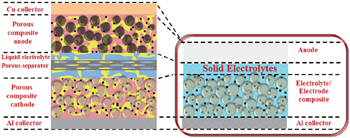
An ASSLiB is composed mainly of cathode, anode, and solid electrolyte, as developed during the latter half of the 20th century. [ 4 , 5 ] ASSLiBs have a simpler structure than the traditional LiBs, and the simplified structure with a solid electrolyte enables higher energy density. [ 6 ] Solid electrolytes not only conduct Li + ions but also serve as the separator, as shown in Fig.
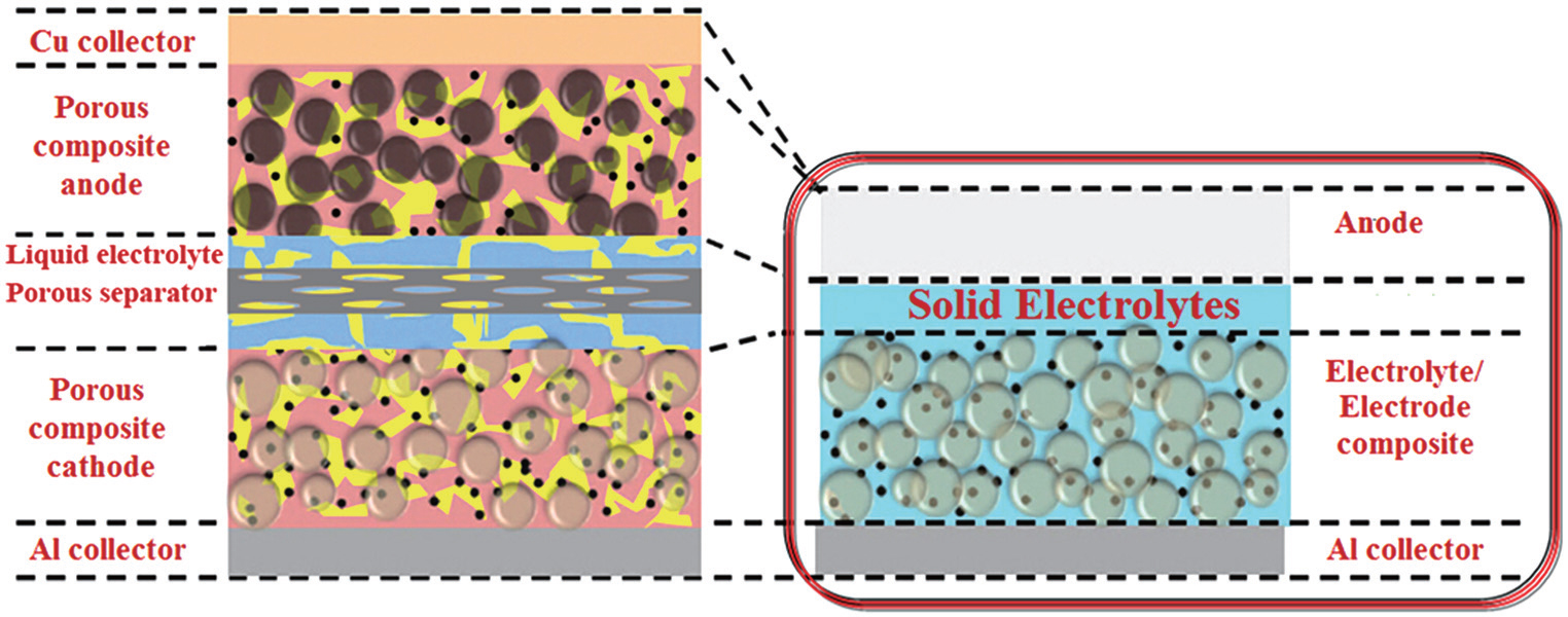 | Fig. 1. Schematic illustration of traditional lithium ion battery and all-solid-state lithium battery. [ 1 ] |
At present, ASSLiBs fall into two categories according to the electrolyte: [ 8 ] polymer-based ASSLiBs with polymer solid electrolytes and ASSLiBs with inorganic solid electrolytes. The advantages of polymer-based ASSLiBs include greater safety, easy preparation, and flexible shape. [ 9 ] However, many problems remain to be solved, such as the instability of the electrolyte/electrode interface, the narrow temperature range of polymers, and the poor mechanical stability. [ 10 , 11 ] By contrast, inorganic solid electrolytes are non-flammable and highly stable mechanically. [ 7 ] The replacement of liquid electrolytes with inorganic solid electrolytes is considered to be the ultimate solution for the safety issues. [ 12 ] Also, inorganic ASSLiBs have a wide electrochemical window, which could be operated under high cut-off voltage.
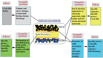
The four fundamental problems in ASSLiBs, shown in Fig. changes of volume and stress in materials during the charge–discharge process, which affect the cycle life and safety; ion and electron migration of electrode materials, which affects specific capacity, specific power, and cycle life; ion migration of electrolytes, affecting specific capacity, specific power, and cycle life; solid-electrolyte/electrode interface structure, affecting
specific power, cycle life, specific capacity, and self-discharge.
 | Fig. 2. The fundamental problems in ASSLiBs. |
The last two points are characteristic scientific problems of ASSLiBs and will be discussed in detail in this review.
Solid electrolytes, also called superfast ionic conductors, are solid materials that exhibit a conductivity comparable with liquid electrolytes at working temperature, i.e., >10 −2 S ·cm −1 , and the activation energy is < 0.5 eV. Solid electrolytes conduct ions, and the charge carriers could be cations, anions, or ion defects; however, solid electrolytes’ electron conductivity is negligible.
The temperature dependence of ion conductivity in solid electrolytes normally follows the Arrhenius law: σT = σ o exp( E a / K B T ), where T , σ o , E a , and K B are the absolute temperature, an exponential factor, the activation energy of ion migration, and the Boltzmann constant, respectively. A linear relation should exist between lg σT and (1/ T ).
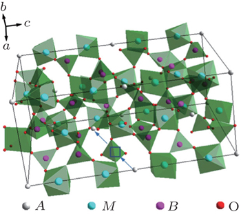
Perovskite is a general term for a structural family of inorganic materials with the structure of CaTiO 3 , [ 13 ] which has a general formula of AB O 3 with alkaline rare or earth metal ions in A sites and transition metal ions in B sites. The ideal perovskite has cubic symmetry with the space group Pm 3 m . The B cation and the A cation are 6-fold and 12-fold coordinated with the oxygen anions, respectively, as shown in Fig.
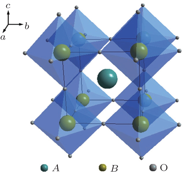 | Fig. 3. Structure schematic of perovskite type electrolytes. |
A series of Li 3 x La 2/3− x TiO 3 was synthesized with Li and La occupying the A positions. Inaguma et al . synthesized Li 3 x La 2/3− x TiO 3 , which exhibited a conductivity exceeding 10 −3 S·cm −1 at room temperature (RT). [ 14 ] The abnormally high ion conductivity of perovskites has aroused strong interest among researchers. The structure of Li 3 x La 2/3− x TiO 3 depends on the composition and the preparation conditions; tetragonal, cubic, or orthogonal structure could be obtained. The conductivity of perovskites is affected mainly by the atoms in the A position, since the size of the Li diffusion channel is determined by the A atoms. Furthermore, the occupation of high-valence La in A positions results in A vacancies, and Li ions transport by the vacancy mechanism. However, Li 3 x La 2/3− x TiO 3 is not suitable for use as an electrolyte, since it is unstable when in contact with lithium metal. Lithium can quickly intercalate into the lattice of Li 3 x La 2/3− x TiO 3 and reduce Ti 4+ to Ti 3+ .
The compounds Na M 2 (PO 4 ) 3 ( M = Ge, Ti, Zr) were studied as early as the 1960s. [ 15 ] The structure was named NASICON (sodium (Na) super (S) ionic (I) conductor (CON)) in 1976, after the modifications Na 1 + x Zr 2 Si x P 3− x O 12 (0 ≤ x ≤ 3), which exhibited high Na ion conductivity, were synthesized and characterized by Goodenough and Hong et al . [ 16 ] NASICON compounds have a general formula of AM 2 ( B O 4 ) 3 , where the A site is occupied by alkali atoms (Li + , Na + , K + ), and the M site is occupied by tetra-valence ions (Ge 4+ , Ti 4+ , Zr 4+ ). The NASICON structure belongs to the 
Lithium superfast ionic conductors are obtained with occupation of Li ions in A sites. Lithium ion conductivity in NASICON structure is related to the channel size, and high conductivity is obtained only when the channel size and the ion size match. [ 17 ] Subramanian et al . reported very low conductivity of LiZr 2 (PO 4 ) 3 , but it could be remarkably improved by substitution of (Hf, Zr, Ti, Sn). [ 18 – 20 ] The highest conductivity is exhibited by LiTi 2 (PO 4 ) 3 , indicating the importance of the match between diffusing ions and channel size. [ 17 ] The highest lithium ion conductivity was obtained for LiTi 2 (PO 4 ) 3 with an optimum cell volume of 1310 Å 3 . The LiTi 2 (PO 4 ) 3 based system has been extensively investigated due to its high ion conductivity. The ion conductivity of LiTi 2 (PO 4 ) 3 could be further enhanced with the substitution of M 3+ for Ti 4+ . Aono et al . studied the conductivity of the Li 1 + x Ti 2− x M x (PO 4 ) 3 ( M = Al, Cr, Ga, Fe, Sc, In, Lu, Y, La) system, and the conductivity was increased more than one order of magnitude. [ 21 ] In particular, Al substitution was most effective, and a maximum conductivity of 7 × 10 −4 S·cm −1 was obtained at 298 K for Li 1.3 Ti 1.7 Al 0.3 (PO 4 ) 3 . [ 21 ] Morimoto et al . prepared Li 1.3 Ti 1.7 Al 0.3 (PO 4 ) 3 by mechanical milling, and its conductivity reached the order of 10 −4 S·cm −1 at RT. [ 22 ] With the same preparation method, Xu et al . prepared a slightly different composition of Li 1.4 Al 0.4 Ti 1.6 (PO 4 ) 3 with conductivity of 5.16 × 10 −4 S·cm −1 at RT. [ 4 ] They also synthesized Li 1.4 Al 0.4 Ti 1.6 (PO 4 ) 3 by spark plasma sintering; it possessed nano-grains with almost theoretical density, [ 4 ] and a very high conductivity of 1.12 × 10 −3 S·cm −1 was obtained. [ 23 ]
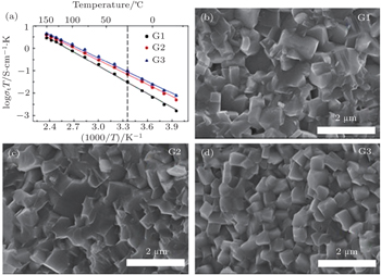
The Li 1 + x Al x Ge 2− x (PO 4 ) 3 (LAGP) system has been investigated due to its high electrochemical stability and wide electrochemical window. [ 25 ] At x = 0.5–0.6, it was reported to exhibit high conductivity and low activation energy at RT. [ 26 ] Li 1.5 Al 0.5 Ge 1.5 (PO 4 ) 3 glass-ceramics were prepared to improve the conductivity, [ 27 , 28 ] and the high conductivity of 6.2 × 10 −4 S·cm −1 was obtained. In recent years, some interesting results on the NASICON structure solid electrolytes have been obtained in our group at Ningbo Institute of Materials Technology and Engineering, Chinese Academy of Sciences. [ 24 ] At present, the third generation (G3) of Li 1.5 Al 0.5 Ge 1.5 (PO 4 ) 3 based microcrystalline materials has been prepared at 100 kg scale, and the ion conductivity of G3 reaches 6.21 × 10 −4 S·cm −1 . The relative density of G3 is over 97%. Figure
In summary, NASICON-structure fast ionic conductors exhibit high RT ion conductivity, high chemical stability, and a wide electrochemical window, and they are suitable for use as solid electrolytes in high voltage ASSLiBs. The future development will focus on optimization of the preparation process, enhancement of grain boundaries and grain conductivity, raising density to further improve RT ionic conductivity and expand the application fields.
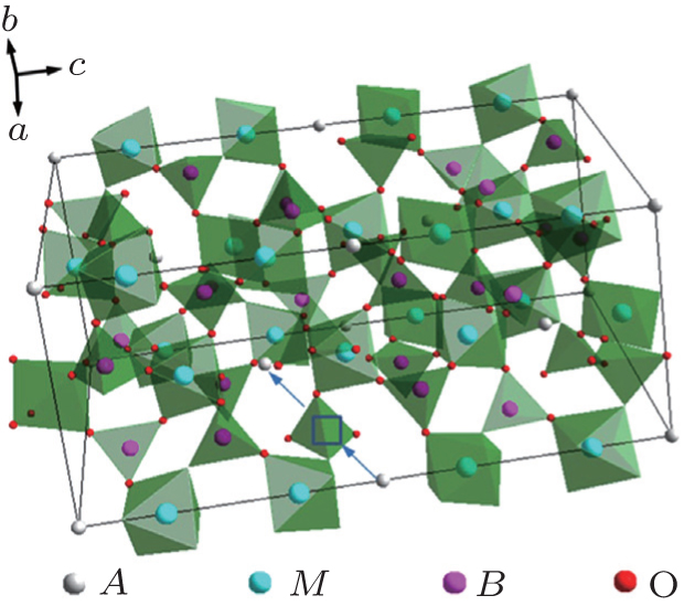 | Fig. 4. Structure schematic of NASICON type electrolytes. |
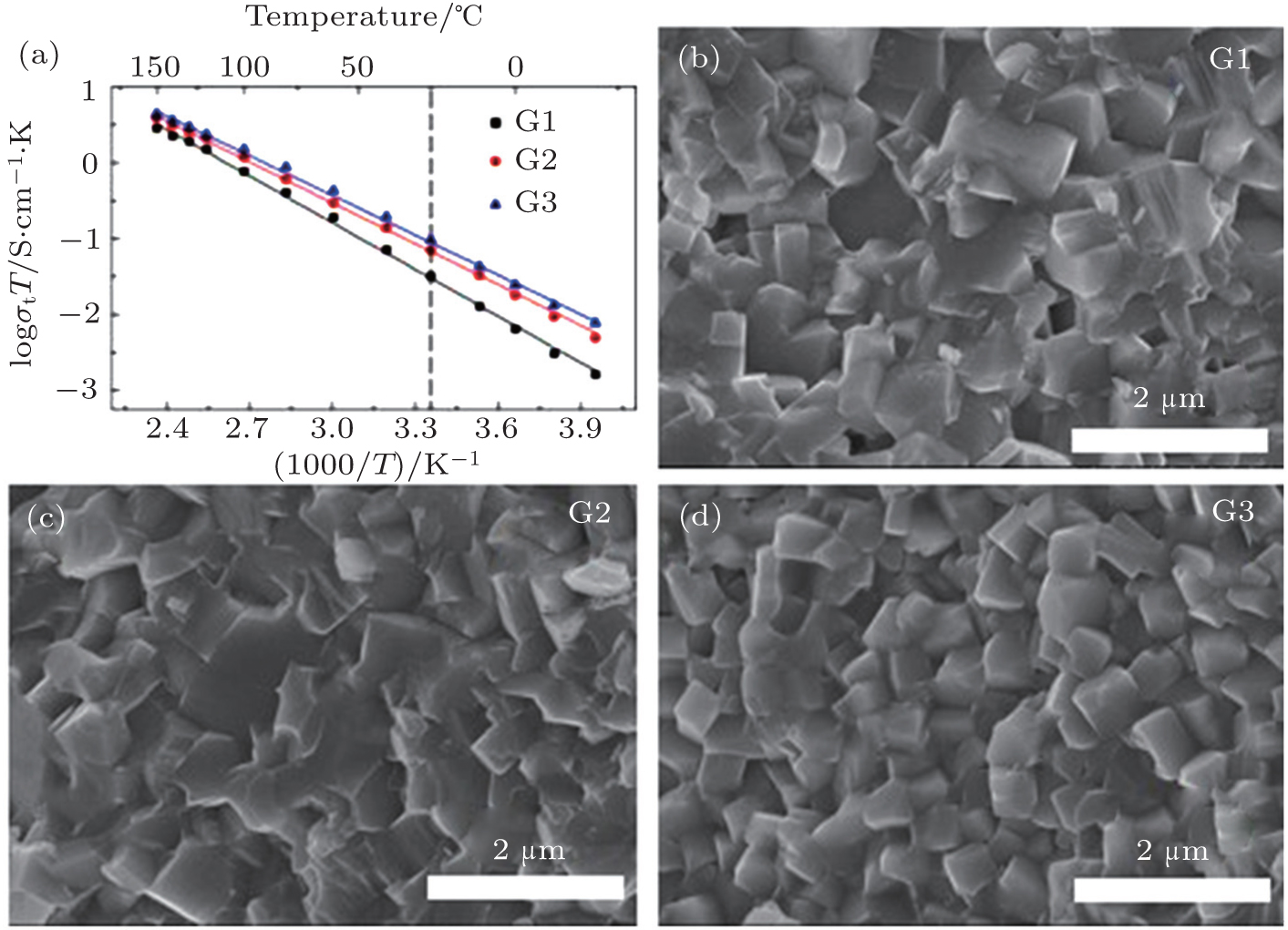 | Fig. 5. (a) Temperature dependence of three generations’ ionic conductivities and (b)–(d) SEM images of three generations of Li 1.5 Al 0.5 Ge 1.5 (PO 4 ) 3 -based microcrystalline samples. [ 24 ] |
The garnet structure has a general formula of A 3 B 2 Si 3 O 12 with space group Ia -3 d , where A is an eight-coordination cation, and B is a six-coordination cation. The first Li-containing garnet structure Li 3 M 2 Ln 3 O 12 ( M = W, Te) was studied by Kasper et al . in 1969. [ 29 ] A new type of garnet structure, Li 5 La 3 M 2 O 12 ( M = Nb, Ta) was found by Mazza in 1988, [ 30 ] where Li occupies the 24d position in the tetrahedra and the 48g position in the octahedra, [ 31 ] as shown in Fig.
The conductivity of Li 7 La 3 Zr 2 O 12 could be further enhanced by the substitution of other metals for Zr. Murugan et al . synthesized cubic Li 7.06 La 3 Y 0.06 Zr 1.94 O 12 with a conductivity of 8.1 × 10 −4 S·cm −1 at RT. [ 39 ] The replacements of La 4+ with Ta 5+ or Nb 5+ could also increase the conductivity over 8 × 10 −4 S· cm −1 , and the activation energy is 0.22–0.35 eV. [ 40 – 42 ] The highest conductivity of garnet-structure compounds is obtained in Li 6.5 La 3 Zr 1.75 Te 0.25 O 12 , which reaches 1.02 × 10 −3 S· cm −1 at RT. [ 43 ]
 | Fig. 6. Structure schematic of Li 5 La 3 M 2 O 12 ( M = Nb, Ta). |
Kennedy was the first to synthesize the Li 2 S–SiS 2 solid electrolyte in 1986, using a melting-quench method. It exhibited ion conductivity in the range of 10 −6 to 10 −3 S· cm −1 . [ 44 , 45 ] Anhydrous Li 2 S and SiS 2 were fixed with a molar ratio of 3:2, and the mixture was doped with LiI and calcinated at 950 °C for 1 h in Ar atmosphere. The composition of 0.6(0.4SiS 2 –0.6Li 2 S)–0.4LiI was found to exhibit the highest conductivity, 1.8 × 10 −3 S· cm −1 , with activation energy of 0.28 eV. Since then, Li 2 S–SiS 2 based glass electrolytes have been widely investigated to improve the ion conductivity and electrochemical stability. [ 46 – 49 ] Morimoto et al . prepared amorphous Li 2 S–SiS 2 by high-energy ball milling. [ 50 ] Samples exhibited conductivity of 1.5 × 10 −4 S· cm −1 . Kondo et al . reported the Li 2 S–SiS 2 system doped with Li 3 PO 4 , which exhibited a conductivity of 6.9 × 10 −4 S· cm −1 , and stability with regard to electrochemical reduction was highly superior. [ 48 ]
A new crystalline material family, lithium superionic conductors ( thio -LISICON), was found in the Li 2 S–GeS 2 –P 2 S 5 system by Murayama et al . in 2001. [ 51 ] The thio -LISICON structure of Li 4− x Ge 1− x P x S 4 is classified into three regions: region I: (0 < x ≤ 0.6), region II: (0.6 < x < 0.8), and region III: (0.8 ≤ x < 1.0), as shown in Fig.
Due to their high ionic conductivity, Li 2 S–P 2 S 5 system lithium ion conductors are extensively studied. Actually, the conductivity of Li 2 S–P 2 S 5 stable phases prepared from solid phase reaction is very low. [ 52 ] However, the Li 2 S–P 2 S 5 amorphous phases prepared by mechanical milling or melt quenching exhibit higher conductivity, and the conductivity of the Li 2 S–P 2 S 5 system could be further improved with the formation of crystalline phases by glass crystallization. [ 52 , 53 ] The enhancement of Li + -ion conductivity in the glass-ceramics is attributed to the precipitation of the meta-stable crystalline phase. [ 53 ] 80Li 2 S–20P 2 S 5 (mol%) and 75Li 2 S–25P 2 S 5 (mol%) were prepared by high-energy ball-milling and subsequent heat-treatment. [ 54 ] The conductivity of 80Li 2 S–20P 2 S 5 (mol%) reached around 10 −3 S·cm −1 . [ 55 ] The composition 75Li 2 S–25P 2 S 5 (mol%) could exhibit several structures depending on the preparation conditions. Li 3 PS 4 has been prepared by high-temperature solid reaction. [ 56 ] β -Li 3 PS 4 was obtained above 190 °C, and transformed to γ -Li 3 PS 4 below 190 °C. [ 56 ] β -Li 3 PS 4 is a highly ion conductive phase, while γ -Li 3 PS 4 is a low ion conductive phase. However, the high-temperature phase β -Li 3 PS 4 can be stable at RT with a porous structure. [ 57 ] The conductivity of β -Li 3 PS 4 is about 1.6 × 10 −4 S·cm −1 and could be improved to 6.3 × 10 −4 S·cm −1 with LiI doping to form a new phase of Li 7 P 2 S 8 I. [ 58 ] Moreover, the conductivity of thio -LISICON structure Li 3 PS 4 could reach 1.0 × 10 −3 S· cm −1 . [ 59 ]
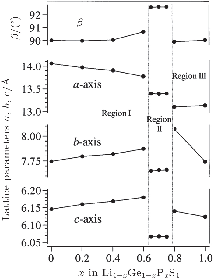 | Fig. 7. Composition dependence of lattice parameters in Li 4− x Ge 1− x P x S 4 , determined by XRD measurements. The lattice parameters plotted in the figure are based on the parent lattice of the LISICON with a × b × c cells. [ 51 ] |
However, the chemical stability of the Li 2 S–P 2 S 5 system is low, and the system is prone to react with moisture to generate H 2 S gas. [ 60 , 61 ] The substitution of oxides in Li 2 S– P 2 S 5 was observed to increase its chemical stability. [ 61 ] Furthermore, the presence of oxygen atoms in Li 2 S–P 2 S 5 was reported to decrease the interface resistance between oxide electrodes and sulfide electrolytes. [ 62 , 63 ] The Li + -ion conductivity of 70Li 2 S–30P 2 S 5 could be further improved by oxide substitution. [ 64 ] Minami et al . reported on a 70Li 2 S–30P 2 S 5 system with P 2 S 3 and P 2 O 5 substituted, respectively. [ 64 ] When P 2 S 3 was substituted, the glass-ceramics with 1 mol% P 2 S 3 exhibited the highest conductivity, and the conductivity increased 29% compared with the pristine sample. [ 64 ] When P 2 O 5 was substituted, the highest conductivity was obtained at a substitution amount of 3% P 2 O 5 , and the conductivity increased 10% compared with the pristine sample. The substitution effects of Li 3 PO 4 are similar to those of P 2 S 3 , which could be related to their complex substitution mechanism. [ 47 ] Moreover, the meta-stable phase Li 7 P 3 S 11 has the highest conductivity of 3.2 × 10 −3 S· cm −1 in the 70Li 2 S–30P 2 S 5 system. [ 52 ] Recently, Seino et al . prepared meta-stable phase Li 7 P 3 S 11 by hot pressing, and the conductivity was as high as 1.7 × 10 −2 S· cm −1 . [ 65 ]
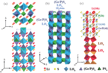
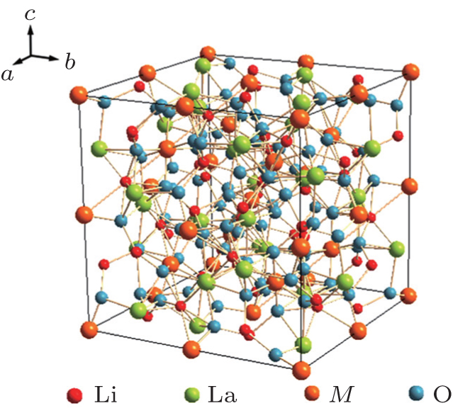
Recently, a new structure, Li 10 GeP 2 S 12 (Fig.
 | Fig. 8. Crystal structure of Li 10 GeP 2 S 12 . (a) The framework structure and lithium ions that participate in ionic conduction. (b) Framework structure of Li 10 GeP 2 S 12 . (c) Conduction pathways of Li + ions. [ 66 ] |
The specific capacity of cathode materials currently in use is less than half that of negative electrode materials. Therefore, high-capacity cathode materials are necessary for lithium-ion batteries with higher energy densities. The most commonly used cathode materials in all-solid-state lithium batteries can be classified into two categories based on the cell potential. [ 69 ] One is lithium transition-metal oxides, with a potential of 3.5–5 V, which are considered to be viable candidates for ASSLiBs because of their highly reversible intercalation/deintercalation reaction and high operating potential. They include LiCoO 2 , [ 70 ] LiNiO 2 , [ 71 ] LiNi 0.8 Co 0.15 Al 0.05 O 2 , [ 72 ] LiNi 0.33 Co 0.33 Mn 0.33 O 2 , [ 73 ] LiMn 2 O 4 , [ 74 ] and LiNi 0.5 Mn 1.5 O 4 . [ 75 ] The other one is sulfur-based materials (S and Li 2 S) and metal sulfides ( M x S y , M generally being a transitional metal) with a potential below 3.0 V, such as Li 2 S, [ 76 ] Li 2 S–C, [ 77 ] S–C, [ 78 ] Li 2 S–Cu, [ 79 ] TiS 2 , [ 80 ] FeS, [ 81 ] FeS 2 , [ 82 ] and NiS. [ 83 , 84 ]
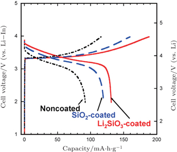
In addition, coating SE on LiCoO 2 particles by pulsed laser deposition [ 70 , 88 ] or in situ wet coating in solution [ 92 , 93 ] is a direct way to improve the lithium-ion conducting paths between electrode and SEs. LiCoO 2 coated with Li 2 S–P 2 S 5 SE by pulsed laser deposition showed a stable reversible capacity of 133 mA·h·g −1 for use as a cathode in the all-solid-state cell. [ 70 ] However, the effect of wet coating SE on LiCoO 2 was limited, due to the low conductivity and unevenness of the SE coating layer. [ 92 , 93 ]
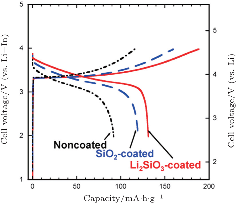 | Fig. 9. Charge–discharge curves of all-solid-state cells, In/80Li 2 S–20P 2 S 5 glass-ceramic/LiCoO 2 with uncoated, SiO 2 -coated, and Li 2 SiO 3 -coated LiCoO 2 . The current density and cutoff voltage are 0.13 mA·cm −2 and 4.6 V (vs. Li), respectively. [ 90 ] |
In order to improve the energy density of ASSLiBs, utilization of active materials with high capacity is effective. Sulfur and lithium sulfide are regarded as promising cathode materials for lithium batteries due to their high theoretical capacities of 1672 mA·h·g −1 and 1168 mA·h·g −1 , respectively. [ 103 ] However, the two major limitations of these two materials are the essential low electronic and Li + -ion conductivities, and capacity fading because of high dissolution of lithium polysulfide into the liquid electrolyte during the electrochemical reactions. [ 104 ] Formation of nanocomposites of sulfur or Li 2 S with various forms of carbon is a useful strategy to improve the electronic conductivity. These nano-sized active particles could simultaneously provide short diffusion lengths for Li + ions. [ 77 ] As to the issue of solubility of the lithium polysulfides, replacing the traditional liquid electrolytes with inorganic SEs seems to be effective. Sulfur-based materials or metal sulfides could be employed as cathodes for ASSLiBs due to their good interface compatibility with sulfide-based solid-state electrolytes and mild operating voltages. [ 105 ]
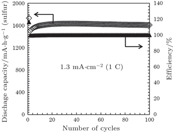
Tatsumisago’s group reported a series of S-nanocarbon and Li 2 S-nanocarbon composites as cathode materials in allsolid- state cells using Li 2 S–P 2 S 5 as SE. [ 77 , 79 , 106 ] The sulfur or Li 2 S cathodes for all-solid batteries were prepared primarily by high-energy mixing or ball-milling of sulfur-based materials with conductive carbons and solid electrolytes. The smooth and adhesive interface among the three components can be realized at nanoscale by mechanical milling. For example, the composite cathode prepared by ball milling a mixture of sulfur, activated carbon, and amorphous SE of Li 1.5 PS 3.3 exhibited a reversible capacity as high as 1600 mA·h·g −1 after 100 cycles at 1 C current density at 25 °C (Fig.
 | Fig. 10. Cycling performance of all-solid-state lithium sulfur (Li/S) cell containing an AC-based positive composite electrode, at 1.3 mA·cm −2 (1 C) at 25 °C. The weight of the positive composite electrode is 1.2 mg. The cut-off voltage is kept between 0.5 V and 2.5 V (vs. Li–In). [ 107 ] |
Compared to sulfur or Li 2 S, metal sulfide nanoparticles or nanocomposites of carbon with metal sulfides, such as FeS, [ 81 ] TiS 2 , [ 80 ] NiS, [ 83 ] NiS-VGCF (vapor grown carbon fiber), [ 84 ] Mo 6 S 8 , and Cu x Mo 6 S 8− y [ 110 ] have similar interfacial stability and high capacity with sulfur-based solid electrolytes. Moreover, they exhibit better rate capability and cyclability because of relatively higher electronic conductivity. For example, NiS nanoparticles synthesized in high-boiling solvents exhibited a large capacity of 680 mA·h·g −1 after 20 cycles at 0.13 mA·cm −2 . [ 83 ] To improve the rate capability of ASSLiBs, NiS-VGCF-SE composites were prepared by coating the electrolyte 80Li 2 S· 20P 2 S 5 onto the NiS-VGCF composite using pulsed laser deposition to form continuous lithium-ion and electron conduction paths for the NiS active material. As a result, NiS-VGCF-SE composite showed a reversible capacity of 430 mA·h·g −1 at a higher current density of 1.3 mA·cm −2 . [ 84 ]
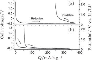
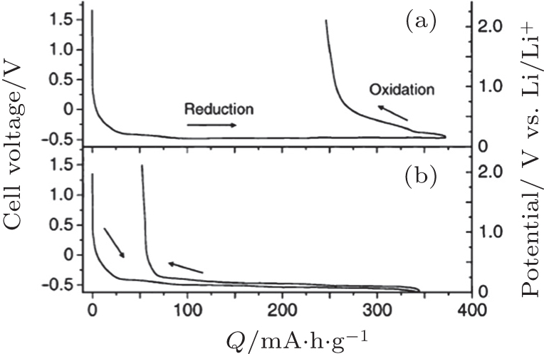 | Fig. 11. Discharge–charge curves of the cell, Li–In/graphite using Li 3 PO 4 –Li 2 S–SiS 2 glass (a) and LiI–Li 2 S–P 2 S 5 (b) as electrolyte. The right vertical axis shows the potential of the working electrode vs. Li/Li + calculated by adding the potential of the counter electrode (0.62 V vs. Li/Li + ) to the cell voltage. [ 118 ] |
The basic problem of all solid–state lithium batteries is their low power density, which results from the large charge transfer resistance at the interface between the electrode and the solid electrolyte. In addition, the rate capability, coulombic efficiency, [ 120 ] and cycle stability are also closely related with the interface. [ 59 , 121 ] Electrochemical impedance spectroscopy (EIS) is a powerful tool to characterize the interfacial resistance in ASSLiBs. [ 75 , 86 , 105 ] Hayashi et al. systematically investigated the interface of In/ Li 2 S–P 2 S 5 /LiCoO 2 cell in ASSLiBs with EIS, finding that the impedance profile at the charge state is composed of one intercept point in the high frequency region and two semicircles in the medium and low frequency regions, corresponding to the resistance of the solid electrolyte layer, the resistance in the positive electrode layer (interfacial resistance between LiCoO 2 and Li 2 S–P 2 S 5 solid electrolyte) and the negative electrode layer, respectively. [ 86 ] The interfacial resistance in the electrode layers accounts for more than 60% of the total resistances. Hence, in order to improve the low rate capability, high overpotential, and large initial irreversible capacity of ASSLiBs, it is necessary to reduce the total resistances of the cell. In particular, improvement of the properties of electrode/electrolytes interfaces would engender a low interfacial resistance and improve the electrochemical performance of ASSLiBs. Specifically, the main challenges inherent in the interface between an electrode and a solid electrolyte are: (i) small contact area, (ii) side reactions by element co-diffusion, (iii) impediment of ion diffusion by space charge layer, and (iv) interface stress induced by volume changes.
Formation of a favorable solid–solid interface between electrode and electrolyte is crucial to achieve excellent performance in solid-state batteries. [ 69 , 122 ] Two useful tactics are mechano-chemical preparation of nanocomposite electrodes and formation of electrolyte on active material by softening the electrolyte or by pulsed laser deposition coating, as shown in Fig.
For the nanocomposite electrodes, the mixture process has an obvious effect on the capacity, and the complete mixture benefits the capacity by increasing the contact area between electrode and electrolyte. [ 123 ] The nanocomposite elec-trodes can be prepared by ball-milling, which not only increases the contact area [ 77 ] but also induces the formation of an amorphous interface layer to enhance the capacity. [ 80 , 124 ] Nanocrystalization of electrodes can also effectively improve their rate capability. [ 109 , 125 ] In addition, a favorable solid–solid interface can be prepared by softening sulfide glass electrolyte at its glass transition temperature. [ 126 ] Besides, the coating of a highly conductive SE on active material particles is a promising technique to form an effective electrode–electrolyte interface and a lithium-ion conducting path in the composite. [ 88 ]
 | Fig. 12. Schematic of several approaches to form good electrode/electrolyte interfaces. [ 69 ] |
Sakuda et al . characterized the interface of LiCoO 2 and Li 2 S–P 2 S 5 with transmission electron microscopy and observed mutual diffusions of Co, P, and S at the interface. [ 86 ] They proposed that an interfacial CoS layer is formed during the charge–discharge process, resulting in the increase of interface resistance and therefore decreasing the discharge capacity. [ 127 ] A Li 2 SiO 3 buffer layer could improve cycle stability and high-rate performances by hindering element diffusions. [ 128 ] To justify this assumption, they coated LiCoO 2 with CoS and NiS respectively, and found that the interface resistance is reduced by each of these coatings, which implies that the presence of a thin CoS layer is not the cause of the large interfacial resistance between LiCoO 2 and Li 2 S–P 2 S 5 . Thus, degradation of the solid electrolyte and/or the LiCoO 2 electrode at the interface is considered to be the main cause of the large interfacial resistance. Thin CoS and NiS coatings act as buffer layers that suppress degradation at the highly reactive interface between charged LiCoO 2 and Li 2 S–P 2 S 5 solid electrolyte. [ 87 ] Besides electron-conductive metal sulfides, ion-conducting oxide materials, such as LiNbO 3 , [ 89 , 100 ] Li 2 O– ZrO 2 , [ 101 ] Li 2 O–SiO 2 , [ 128 ] Li 4 Ti 5 O 12 , [ 12 , 72 ] and TaO 3 , [ 62 ] were also coated on oxide cathode materials by a wet-chemical method or atomic layer deposition in order to suppress the chemical reactions between the sulfide electrolytes and the oxide cathodes. Similar interface diffusion is found between oxide electrolytes and oxide cathodes, and the similar surface coating modification of Nb layer was chosen to reduce this interfacial resistance. [ 129 , 130 ]
For the interface between an oxide electrode and a sulfide solid electrolyte, Takada et al . attributed the rate-determining step of the battery reactions to ionic transport at the interface rather than bulk in the battery components. [ 7 , 12 , 72 , 89 , 131 , 132 ] They assumed that only Li + ions are mobile in the all-solidstate lithium batteries, with no side reaction at the interface. [ 7 ] Ionic conductors often exhibit anomalous transport properties at their surface or at their interface with various other materials. Such phenomena are attributed to a space-charge layer at the surface or the interface that has different mobile-ion concentration from the bulk, as shown in Fig.
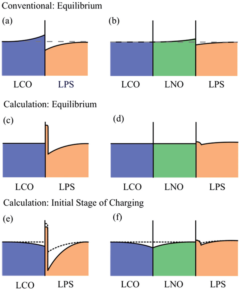 | Fig. 13. Schematic illustrations of interfacial Li concentration. The equilibrium concentrations expected by the conventional model and indicated by the present calculations for the LCO/LPS interface ((a) and (c)) as well as the LCO/LNO/LPS ((b) and (d)). The Li concentrations in panels (e) and (f) describe the expected changes at the initial stage of charging for both interfaces proposed in the calculation. [ 85 ] |
When LiCoO 2 is lithiated/delithiated, the volume of LiCoO 2 changes repeatedly. This change occurs uniformly throughout the electrode, including the interface. So the electrode-solid electrolyte interface is stressed by the change of LiCoO 2 volume, and the stress increases the local distortion at the electrode, increasing resistance for the charge transfer reaction. An oxide electrolyte buffer layer NbO 2 film is introduced between electrolytes and electrodes, which could effectively reduce the change of Co–O bonding, and thus decrease the interface stress. [ 130 ] As to the electrode materials with massive volume change during charge and discharge, such as S and Li 2 S (∼179% volumetric expansion during lithiation from S to Li 2 S [ 80 ] ), constructing a nanocomposite structure of sulfur or Li 2 S is a good strategy to address the stress problem. The nano-size active materials could relieve the stresses induced by the volume during cycling. At the same time, carbon materials could act as a buffer phase to the volume change. [ 76 , 108 ] In film ASSLiBs, an effect of mismatch strain caused by the lattice expansion and contraction of electrode materials can cause high stress concentration along the interface, eventually yielding cracks around the interface. Introduction of amorphous layers with high ionic conductivity at the interface could suppress the interface separation as well as the consequent increase of the interfacial resistance. [ 135 ]
In recent years, great progress has been made in ASSLiBs, mainly in addressing the electrode/electrolyte interface problems and elevating their energy and power densities. [ 69 ] A great many patents about all-solid-state lithium batteries have emerged, centering on preparation of the solid state electrolyte, surface modification technologies, and battery fabrication technologies.
Toyota Motors, for example, has been working on allsolid- state lithium batteries for many years and regards it as a medium-term advanced battery solution. A prototype allsolid- state lithium battery, shown in Fig.
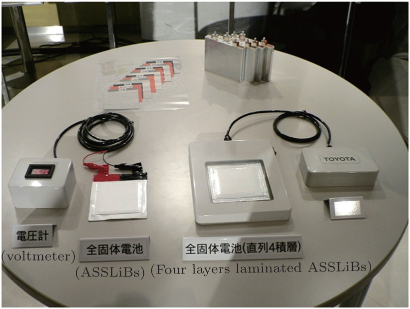 | Fig. 14. Toyota Motors’ all-solid-state lithium batteries. [ 136 ] |
In addition, Idemitsu Kosan Co., Ltd. exhibited an A6- size laminated ASSLiB in 2010. The battery, with inorganic sulfide electrolytes, is safer and features high-temperature performance, resistance to overdischarge, and potentially higher energy density than the traditional LiBs with liquid electrolytes. The positive and negative electrodes in this prototype A6-size battery are the same as those of mainstream LiBs. The A6-size battery with cells connected in a series has an output voltage of 14–16 V. The solid electrolyte membrane used is about 100 μm thick. Idemitsu Kosan plans to reduce the thickness to 10–20 μm to lower the resistance and is searching for electrode materials that are compatible with the electrolyte. And, in theory, it is possible to increase the gravimetric energy density to 300 W·h/kg.
Samsung R&D Institute Japan, in cooperation with Samsung Electronics Co., Ltd., developed a 1 A·h class ASSLiB using a Li 2 O–ZrO 2 -coated NCA cathode, an artificial graphite anode, and a sulfide based electrolyte (80%Li 2 S–20%P 2 S 5 ) in 2014. [ 101 ] The standard-type single cells are fabricated by the wet printing method, and the 1 A·h class all-solid-state battery consists of three parallel stacks of the single cells. The interface resistance between NCA and sulfides is significantly reduced by the Li 2 O–ZrO 2 coating, and the total cell resistance is approximately one quarter that of a cell without the coating. The battery displays 82% and 85% capacity retention after 100 cycles at 25 °C and 60 °C without any artificial external pressure, which convincingly demonstrates the high temperature stability of the all-solid-state battery. In subsequent work, [ 137 ] the electrochemical performance of large size ASSLiBs was further improved by using sulfide electrolyte with high ionic conductivity and thinner electrolyte layers, as well as an optimized fabrication process.
Recently, interesting results have been obtained in our group regarding the development of all-solid-state lithium batteries, including cathode materials, inorganic solid state electrolytes, and surface modification between electrode and electrolyte. [ 1 , 24 ] All-solid-state lithium batteries with A·h-class capacity have been successfully prepared by direct cold pressing using sulfide electrolytes and surface-modified LiCoO 2 -based cathodes. The cathode delivered a discharge-specific capacity of 120 mA·h·g −1 , almost as high as that of the traditional LiBs. The interface resistance has been reduced to 8 m Ω ·cm −2 , which is on the same level as Toyota Motors’ prototypes.
Although ASSLiBs based on inorganic solid electrolytes have clearly demonstrated their great possibilities for electric vehicles and large-scale energy storage systems, further development is still required to improve their energy density, rate capability, and cycling stability, while ensuring excellent safety. Actually, they are still far from being commercialized for industrial applications, which requires systematical studies and will be a complicated process.
Making ASSLiBs usable outside the laboratory involves multiple factors such as solid electrolytes, electrodes, interface properties, and construction design. The high cost and very small production scale of solid state electrolytes with high ionic conductivity hinder the application of ASSLiBs. Meanwhile, ASSLiBs still suffer from inferior power density and poor cycle life, due to the high transfer resistance of lithium ions between the electrodes and solid electrolytes. Thus, at this stage, the direction for research exploring ASSLiBs for commercial applications is to develop new cathodes based on the conversion reaction mechanism with low or even zero strain and energy levels well matched with the electrolytes. All of these together are expected to yield new material systems with high capacity. In addition, the use of lithium metal in anodes will be another thrust of ASSLiB development. Another is the design of novel SEs with high lithium-ion conductivity at room temperature and wide electrochemical window. Meanwhile, future SEs should show excellent chemical stability in the presence of metallic lithium. Also, new methods should be proposed to reduce the interfacial resistance between the electrode and electrolyte. Finally, the optimal combination of different fabrication processes and equipment automation as well as device design are necessary for the realization of ASSLiBs with high capacity, low cost, and high yield.
In summary, scientific and technical research on ASSLiBs is progressing gradually. The current achievements indicate that ASSLiBs with high energy density are promising candidates for large-scale energy storage and even electric vehicle applications.
| 1 | |
| 2 | |
| 3 | |
| 4 | |
| 5 | |
| 6 | |
| 7 | |
| 8 | |
| 9 | |
| 10 | |
| 11 | |
| 12 | |
| 13 | |
| 14 | |
| 15 | |
| 16 | |
| 17 | |
| 18 | |
| 19 | |
| 20 | |
| 21 | |
| 22 | |
| 23 | |
| 24 | |
| 25 | |
| 26 | |
| 27 | |
| 28 | |
| 29 | |
| 30 | |
| 31 | |
| 32 | |
| 33 | |
| 34 | |
| 35 | |
| 36 | |
| 37 | |
| 38 | |
| 39 | |
| 40 | |
| 41 | |
| 42 | |
| 43 | |
| 44 | |
| 45 | |
| 46 | |
| 47 | |
| 48 | |
| 49 | |
| 50 | |
| 51 | |
| 52 | |
| 53 | |
| 54 | |
| 55 | |
| 56 | |
| 57 | |
| 58 | |
| 59 | |
| 60 | |
| 61 | |
| 62 | |
| 63 | |
| 64 | |
| 65 | |
| 66 | |
| 67 | |
| 68 | |
| 69 | |
| 70 | |
| 71 | |
| 72 | |
| 73 | |
| 74 | |
| 75 | |
| 76 | |
| 77 | |
| 78 | |
| 79 | |
| 80 | |
| 81 | |
| 82 | |
| 83 | |
| 84 | |
| 85 | |
| 86 | |
| 87 | |
| 88 | |
| 89 | |
| 90 | |
| 91 | |
| 92 | |
| 93 | |
| 94 | |
| 95 | |
| 96 | |
| 97 | |
| 98 | |
| 99 | |
| 100 | |
| 101 | |
| 102 | |
| 103 | |
| 104 | |
| 105 | |
| 106 | |
| 107 | |
| 108 | |
| 109 | |
| 110 | |
| 111 | |
| 112 | |
| 113 | |
| 114 | |
| 115 | |
| 116 | |
| 117 | |
| 118 | |
| 119 | |
| 120 | |
| 121 | |
| 122 | |
| 123 | |
| 124 | |
| 125 | |
| 126 | |
| 127 | |
| 128 | |
| 129 | |
| 130 | |
| 131 | |
| 132 | |
| 133 | |
| 134 | |
| 135 | |
| 136 | |
| 137 |