Quantum dynamics of charge transfer on the one-dimensional lattice: Wave packet spreading and recurrence
Likhachev V N , Shevaleevskii O I , Vinogradov G A †,
Emanuel Institute of Biochemical Physics, Russian Academy of Sciences, Moscow, Russian Federation


† Corresponding author. E-mail: gvin@deom.chph.ras.ru

Abstract
Abstract

The wave function temporal evolution on the one-dimensional (1D) lattice is considered in the tight-binding approximation. The lattice consists of N equal sites and one impurity site (donor). The donor differs from other lattice sites by the on-site electron energy E and the intersite coupling C . The moving wave packet is formed from the wave function initially localized on the donor. The exact solution for the wave packet velocity and the shape is derived at different values E and C . The velocity has the maximal possible group velocity v = 2. The wave packet width grows with time ∼ t 1/3 and its amplitude decreases ∼ t −1/3 . The wave packet reflects multiply from the lattice ends. Analytical expressions for the wave packet front propagation and recurrence are in good agreement with numeric simulations.

1. Introduction

Charge transfer (CT) is the key event in many processes in living and inorganic matter; photosynthesis, breathing and many others are the well known examples in living matter. [ 1 6 ] Very efficient CT was found later in synthetics analogous of DNA and polypeptides. [ 7 11 ] These substances have well organized structures consisting of repeating units, DNA bases (usually adenine) or peptide groups, and represent very good models for CT in one-dimensional systems.

The tight-binding approximation (TBA) is an efficient tool to study the CT. This approach is dated back to the Slater– Koster paper. [ 12 ] The TBA single-particle Hamiltonian can be written as , where ξ i , j is the intersite coupling between i -th and j -th sites (known also as the “hopping integral”), ɛ i is the on-site energy on the i -th site. The wave function is constructed as the superposition of wave functions for isolated sites.

Many efforts were undertaken to study the wave function evolution using the TBA approximation. One well investigated example is the TBA on the disordered lattice. The case of the static disorder, when on-site energies take random values, received special attention. The Anderson localization [ 13 ] was studied extensively employing the TBA Hamiltonian. [ 14 18 ]

Two models of random values distribution are studied most often. In the first model, random on-site energies ɛ i are chosen uniformly from the interval [− W /2, W /2], with W denoting the disorder strength. [ 19 , 20 ] Random values in the second model are determined as ɛ i = λ cos(2 πiσ + ϕ ). On-site energies are random values if σ is incommensurate with the lattice period. [ 21 , 22 ]

It has been known that if the disorder strength is moderately small, then the moving wave packets are formed from the initially localized wave function. This moving wave function pulse can transport the charge. In studies of the wave packet dynamics it was found that the wave packet initially moves ballistically ∼ t , but at large times the wave packet movement is diffuse ∼ t β with β taking a wide range of values. [ 23 , 24 ] By virtue of problems associated with the investigations of random lattices, most of the studies were performed by approximate methods or numerically.

In the present paper, we consider the problem of the wave function temporal evolution. The TBA approximation is utilized. The lattice is homogeneous, i.e., both types of disorder–diagonal and off-diagonal, are absent. The wave function is initially localized on one site, i.e., ψ j ( t = 0) = δ j ,1 . The formed moving wave packet can multiply reflect from the ends of the lattice. It should be remembered that the recurrence phenomena to the initial state are in general well known. The Fermi–Pasta–Ulam recurrence is an example of nonlinear classical dynamics. [ 25 , 26 ] The other example is the interaction of the isolated vibrational mode with the continuous spectrum. [ 27 ]

The recurrence in quantum systems was considered by Zwanzig [ 28 ] for the discrete equidistant spectrum where a single level is initially occupied. The analysis of the Zwanzig’s problem was performed for the resonance [ 29 ] and for the non-resonance [ 30 ] cases.

There is a further point to be outlined. The considered TBA model can also govern the evolution of vibrational excitations. The vibrational energy transport in molecular wires was considered by Benserskii and coauthors. [ 31 , 32 ] The recurrence phenomena (Loschmidt echo) in molecular chains and nanoparticles was also analyzed. [ 29 ]

In the present paper we thoroughly analyze the simplest case of the defect-free lattice. Nevertheless the considered model can be relevant to systems with defects if the disorder strength is not too large. It is known for the three-dimensional lattices, that the critical value W , below which the system is conductive, is rather large, W cr ≈ 8.59 ± 0.05. [ 33 ]

It worth mentioning that Anderson’s localization theorem [ 13 ] is, strictly speaking, valid for one-dimensional systems in the thermodynamical limit ( N → ∞). The situation differs for the final-sized systems. There is the scaling which relates the parameters N and W cr . [ 33 38 ] But W cr does not depend on N in one-dimensional systems and, according to our preliminary results, lies in the region W cr ≈ 2. It means that if the diagonal disorder strength W ≲ 2 then results obtained for the defect-free lattice can be applicable to systems with defects.

If defects are off-diagonal, e.g., due to thermal fluctuations, then the above mentioned arguments are also valid. The defect-free approximation is fulfilled if the temperature is not too high ( kT /2 in one-dimensional systems should be compared with a critical value W cr ).

Exact expressions are also derived for the wave packet shape and velocity at arbitrary time instants including the wave packet parameters after reflections. This is done for the most interesting case when the wave function is initially totally localized on the lattice end which plays the role of an electron donor in experiments on the charge transfer in DNA. [ 8 , 9 ]

The “electron ping–pong” was found experimentally in DNA, [ 39 ] when a charge is triggered consecutively within the same DNA duplex after a charge injection. This phenomenon is also considered and analytical expressions for the wavefunction amplitude on the electron donor are derived.

The considered problem is relevant to the charge transport and our results mimic to some degree the numerous experiments on charge transfer in low-dimensional systems. Because the wave function evolution is governed by the quantum mechanics laws, the problem under consideration is designated as the quantum dynamics of charge transfer.

2. Setting up a problem

We consider the lattice consisting of ( N +1) sites. The left-most site is the “electron donor”. The wave function is initially totally localized on this site. Other N sites are a “reservoir” through which the wave function spreads.

In the second quantization representation, the TBA Hamiltonian is of the form

where a +/− is the creation/annihilation operator on the donor; – analogous for j -th site in the reservoir ( j = 1, 2, …, N ), E is the on-site energy on the donor, C is the intersite coupling between the donor and the first site of the reservoir, ξ j −1, j is the intersite coupling for the nearest neighbor sites in the reservoir, and ɛ j is on-site energy on the j -th lattice site.

We consider a simple model when all on-site energies of the reservoir are equal and ɛ j = const = 0, which corresponds to the choice of the reference point for the electron energy. All intersite couplings on the lattice ξ j −1, j = 1, which corresponds to the choice of the energy unit. In general, E ≠ 0 and C ≠ 1 for the coupling between the donor and the reservoir.

It is instructive to rewrite the Hamiltonian ( 1 ) in the matrix representation for the sake of convenience

Matrix elements related to the reservoir are highlighted in bold. The discrete wave function is the ( N + 1)-vector

where a ( t ) is the wave function amplitude on the donor and b j ( t ) ( j = 1,2, …, N ) are amplitudes on reservoir sites.

The problem is to find how the electronic populations on all sites change in time. The dimensionless ( ħ = 1) Schrödinger equations for the wave function evolution have the form

with the initial conditions a ( t = 0) = 1 and b j ( t = 0) = 0 ( j = 1,2, …, N ). Dots over a ( t ) and b j ( t ) mean the time derivatives. The characteristic quantum time unit ∼ ħ / 〈 ξ 〉 and 〈 ξ 〉 is the typical value of the intersite coupling energy (〈 ξ 〉 = 1 in Eq. ( 4 )). The length unit is the lattice period.

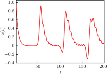
If Eq. ( 4 ) is integrated numerically then the phenomenon of recurrence, i.e., multiple returning to the initial state, is observed (the electronic “ping-pong” was found experimentally [ 39 ] ). The result is shown in Fig.  1 .

Fig. 1. The dependence of the wave function amplitude a ( t ) on the donor versus time. The wave function returns many times (three times in the figure) to the donor with a slightly decreasing amplitude. Parameters: .

The goal of the present paper is to consider the wave packet spreading through the lattice and its reflections from the lattice ends. The quantum dynamical problem of the wave function evolution can be considered as the interaction of the donor with the reservoir. It is solved using the expansion in terms of the eigenfunctions of the reservoir. The reservoir is represented by the N × N tridiagonal matrix with zero leading diagonal and the unity values on the secondary diagonals (highlighted in bold in Eq. ( 2 )). Eigenvalues ɛ ( k ) and eigenfunctions q j ( k ) of this matrix are well known as

It is convenient to consider the problem in terms of amplitudes of modes b ( k ) instead of amplitudes on the lattice sites b j . These values are related by the orthogonal relationship

and then, system ( 4 ) can be rewritten in the form

Amplitudes b ( k , t ) in Eq. ( 7 ) can be expressed through amplitude a ( t )

Substituting this expression into Eq. ( 7 ) for a ( t ), one can get the integro-differential equation for the amplitude a ( t ) on the donor

where the kernel B N ( t ) is given by the following sum:

In the next section, we solve Eq. ( 9 ) for the amplitude a ( t ) on the donor and then discuss the formation of a wave packet pulse at time less than the time of the first reflection from the right end of the lattice.

3. The decay of the initial state a ( t = 0) = 1 in the semi-infinite lattice

Initially, we consider the decay kinetics of the initial state a ( t = 0) = 1 in the semi-infinite lattice ( N → ∞). The amplitude on the donor is labelled by a 0 ( t ) in this case. The limit N → ∞ for the kernel B N ( t ) is also used. The expression for B N ( t ) is denoted by B 0 ( t ) at N → ∞. In this limit, equation ( 10 ) transforms to the integral with the solution [ 40 ]

where J 0 and J 2 are Bessel functions of corresponding orders. Then one gets the following equation for the amplitude a 0 ( t ):

This first-order differential equation can be solved using the Laplace transformation

where the Laplace transform B 0 ( p ) of the function B 0 ( t ) [ 40 ]

The amplitude a 0 ( t ) can be obtained by the inverse Laplace transformation

This form of a 0 ( t ) is very inconvenient for both the analysis and numerical computations (integral with the upper infinite limit converges very slowly). This integral obtains a more convenient form if the integration contour is closed around the cut [−2i, +2i]. If this takes place, the square root must be represented as . The integration contour can be closed if amplitude a 0 ( p ) has no poles. Assuming that poles are absent, closing the integration contour and summing the integrals along both sides of the cut, one gets the following expression for the amplitude a 0 ( t ):

Few special cases can be noted, when the integral ( 16 ) is calculated explicitly and the amplitude a 0 ( t ) is expressed in terms of Bessel functions [ 40 ]

An integro-differential equation for the amplitude a 0 ( t ) is additionally derived in Appendix A, and its solution is obtained as a series of Bessel functions. The series is rather cumbersome, but expressions take simple forms in several particular cases.

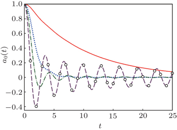
Figure  2 shows the dependence of amplitude a 0 ( t ) calculated according to Eq. ( 16 ) versus time at E = 0 and at different values of the intersite coupling C . The comparison with the accurate result is also shown (“accurate” result means the numeric integration of Eq. ( 4 ).

Fig. 2. The dependence of the amplitude a 0 ( t ), calculated according to Eq. ( 16 ), versus time at E = 0. Solid line: C 2 = 0.1; dotted line: C 2 = 0.5; dash-dotted line: C 2 = 1; dashed line: C 2 = 2. Empty circles: accurate result for C 2 = 2, when a 0 ( t ) = J 0 (2 t ).

The time dependence of the amplitude a 0 ( t ) for small C can be estimated by the Fermi’s golden rule, when the perturbation approximation in small parameter C 2 is used, and when an exponential decay occurs,

More accurate expression for the amplitude a 0 ( t ) at small values of parameter C is given in Appendix B.

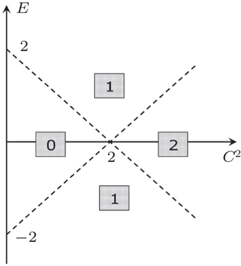
Now the case when the amplitude a 0 ( p ) has poles is considered. An analysis shows that one pole exists in the domain E > 2 − C 2 , and two poles, when E < C 2 − 2. There are no poles in the domain | E | < 2 − C 2 ( C 2 < 2). Figure  3 shows the number of poles versus the values of parameters E and C .

As an example, we consider the case of one pole in the domain E > 2 − C 2 ( C 2 < 2). The pole is at the point p = − i ɛ ( ɛ > 2). The relation between parameters E and C follows from Eq. ( 15 ) as

The contribution Δa 0 from the pole is equal to

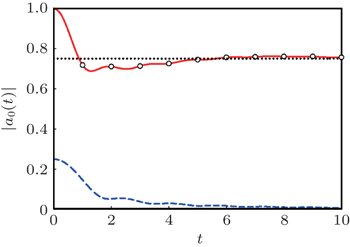
The full amplitude is then the sum of the leading term ( 16 ) and the pole contribution ( 20 ). The time dependence of amplitude | a ( t )|, when one pole exists, is shown in Fig.  4 . In this case, the wave function amplitude on the donor does not decrease to zero and a 0 ( t )| t → ∞ = 0.75. It means that 75% of the wave function is captured by the bound state on the donor.

Fig. 3. Number of poles of the integrand of function Eq. ( 16 ) in domains divided by dashed lines.
Fig. 4. The dependence of amplitude a 0 ( t ) on the donor versus time (solid line) in the presence of one pole. Dashed line: contribution to amplitude from the integral summand Eq. ( 16 ); dotted line: modulus of the pole summand equal to 0.75 Eq. ( 20 ); empty circles: exact numerical result. Parameters: E = 2, C = 1 ( ɛ = 2.5).

It is shown in Appendix C that if | E | > 2 − C 2 ( C 2 < 2), then there exists the bound state localized at the lattice end on the donor. The value ɛ (see Eq. ( 19 )) is the energy of this localized state and its contribution to the amplitude a 0 ( t ) coincides with the contribution from the pole summand. Note also that the integral term ( 16 ) is the contribution to the amplitude from the continuous spectrum which lies in the interval [−2, 2]. A fraction of the initial state is captured by this localized state and the smaller fraction of the initial state goes out to the reservoir. The effect of returning to the initial state also decreases. This case (existence of a pole) seems less interesting and we consider only an absence of the localized state when the integral ( 16 ) is the exact result for amplitude a 0 ( t ).

Such a detailed analysis of the amplitude a 0 ( t ) decaying in the semi-infinite lattice is performed due to two reasons. First, the decay kinetics in the semi-infinite lattice coincides with the kinetic in the finite lattice consisting of N sites in the time range 0 ≤ t N /2. Second, as will be shown below, the full amplitude in the finite lattice can be represented as a sum of partial amplitudes, the first of which is just the amplitude a 0 ( t ) studied above in such detail.

4. Wave packet spreading through the lattice

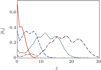
In this section, we will consider the quantum dynamics of the wave function on the lattice, i.e., amplitudes b j ( t ) variation with time. The moving wave packet gradually gains a well formed shape with a sharp leading front. This behavior is shown in Fig.  5 .

Fig. 5. Wave packets at different time instants. Here, t = 2 (solid line); t = 5 (dashed line); t = 10 (dotted line); t = 15 (dash-dotted line). Site j = 0 corresponds to | a 0 ( t )|. Parameters: E = 1, C 2 = 0.5, N = 100. Numerical results coincide with analytical results with very high accuracy and are not shown.

An expression for amplitudes b j ( t ) is obtained substituting the expression ( 8 ) for the mode amplitudes b ( k , t ) into expression ( 6 ). Then one obtains

Initially, we consider the case of semi-infinite lattice ( N → ∞). Changing the summation in Eq. ( 21 ) by integration and replacing a ( t ) by a 0 ( t ), the following expression can be obtained:

where ɛ ( k ) = 2 cos( k ).

We consider the case when time t is so large that the amplitude a 0 ( t ) becomes very small, | a 0 ( t )| ≪ 1. Then the upper limit in the integration over time in Eq. ( 22 ) is infinity. The obtained integral is the Laplace transformation a 0 ( p ) taken at p = − i ɛ ( k ). As a result, we have

Expression ( 23 ) can be formally generalized on the negative values of index j . Having this in mind, the multiplier sin( k j ) is represented as the difference of two exponentials. Then expression ( 23 ) describes the superposition of two wave pulses freely travelling leftward and rightward in the infinite (to both sides) lattice. Every pulse is normalized to unity. We consider separately the wave function pulse running to the right. This pulse is denoted by

The considered pulse b j ( t ) (in the domain j > 0) is the following difference:

The addend is the “tail” of the pulse b j ( t ), and it is small at large times, e.g., ∼ 1/ t . Then is assumed to be a good approximation for b j ( t ). The snapshots of the pulse at different time instants calculated according to Eq. ( 24 ) are shown in Fig.  6 . One can see that the restriction by the pulse is a very good approximation.

Fig. 6. Snapshots of the pulse in semi-infinite lattice at t = 25 (solid line); t = 50 (dotted line); t = 75 (dashed line). Calculations according to Eq. ( 24 ). Empty circles: numeric integration of Eq. ( 4 ). The coincidence of the numeric and analytical results is also very good for t = 50 and t = 75 (mean square root error (MSRE) ≲ 10 −4 ). Here, E = 1, C = 0.5, N = 200.

Expression (see Eq. ( 24 )) is a reliable approximation for the spreading pulse on the time interval t N /2 for the finite but comparatively long lattices. Moreover, as will be demonstrated below, this expression allows one to describe the pulse reflection from the lattice end occurring for the time interval N /2 ≲ t N .

We analyze the expression ( 24 ) at large time. Because the integrand is the fast oscillating function, the stationary phase method can be applied. If j < t /2, then two stationary points exist. They are determined by the equality sin( k ) = j /2 t , and then the following expression can be obtained:

Here, f ( k ) is the integrand in Eq. ( 24 ).

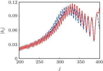
Figure  7 shows the comparison of expression ( 26 ), obtained in the stationary phase approximation, with the accurate answer.

Fig. 7. The pulse leading edge at t = 200. Dashed line represents the numeric result, solid line represents the asymptotic expansion ( 26 ). Here, E = 1, C 2 = 2, N = 500.

If j ≈ 2 t , then both stationary points lie close to k = π /2 and the stationary phase method gives false results (the answer diverges if both points coincide). We consider the region j ≈ 2 t , corresponding to the pulse maximum and its leading edge, in more details. In this case, the expression for amplitudes ( 24 ) can be simplified
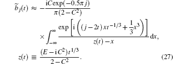
If | z ( t )| ≫ 1 (what is valid for t ≫ 1), then the asymptotic expansion of Eq. ( 26 ) can be rewritten as a series in Airy function and its derivatives

Thereafter, we can write an approximate expression for the pulse leading edge. Using the asymptotic of the Airy function, one can notice that the dominant term, describing the leading edge, has the form:

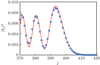
Figure  8 shows the comparison of the asymptotic expansion ( 28 ) with the numeric answer.

Fig. 8. The pulse front at t = 200 ( E = 1, C 2 = 2). Empty circles: numeric result, solid line: asymptotic expansion ( 28 ). Here, MSRE ≲ 10 −3 .

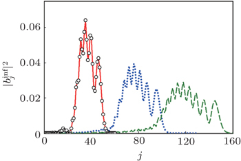
Expression ( 29 ) allows one to describe qualitatively the pulse shape. The dependence on the lattice number j is defined by the argument ( j − 2 t ) t −1/3 . One can notice that the pulse front slowly increases its width ∝ t 1/3 and the amplitude decreases ∝ t −1/3 . This signature becomes apparent only at large values of C and E and at long times. The deviation from this behavior at short times is explained by the fact that the integral in Eq. ( 27 ) over x is a number at fixed j and t . The complex value z ( t ) stands in the denominator with the pole in the complex plane at a distance ∼ C 2 t 1/3 from the real axis. The integral value changes essentially when the asymptotic | z ( t )| ≫ 1 is not fulfilled.

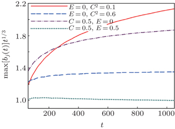
Figure  9 shows the dependence of max | b j ( t )| t 1/3 versus time at different C and E values. When max| b j ( t )| t 1/3 reaches the constant value, the pulse amplitude becomes ∝ t −1/3 .

Fig. 9. Time dependencies of max| b j ( t )| t 1/3 at different (“small” and “large”) values of E and C shown in insert. The time dependence ∝ t −1/3 is not fulfilled at E = 0, C 2 = 0.1, and C = 0.5, E = 0 even at time t = 10 3 , but rather quickly ( t ≈ 200) this dependence is satisfied at large E and C . Here, time range 0 ≤ t ≤ 1000, N = 550.

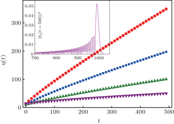
The pulse width also changes. The wave packet width can be estimated by the radius of the quantum excitation defined in the considered model as

If the excitation is localized on one site then η = 1. When the excitation is homogeneously distributed over all sites, i.e. then η N . Figure  10 shows the dependencies η ( t ) at different intersite couplings C . It is easy to notice that the radii of quantum excitations differ significantly for different C values at t = 500. The wave packet spreads practically homogeneously over the lattice at C = 1.25 and η ( t = 500) ≈ 325, while η ( t = 500) ≈ 38 at C = 0.5. In the latter case the wave packet retains its sharp maximum after travelling an even longer distance (≈ 1000 lattice sites, see insert to Fig.  10 ).

Fig. 10. Time dependencies of pulse radii η ( t ) at different values of the intercite coupling C . Here, C = 1.25 (circles), C = 1.0 (squares), C = 0.75 (triangles up), C = 0.5 (triangles down). Squared modules | b j ( t )| 2 at the time instant t = 2000 for C = 0.5 are shown in the inset. Here, E = 0, N = 550.

The velocity of the pulse front is 2, maximal possible group velocity. The leading edge has a sharp profile. Thus, if the finite lattice is considered, then until the front achieves the lattice end, its propagation is the same as in the infinite lattice. The pulse front achieves the lattice end at t N /2. After that the pulse reflects from the lattice end and the front moves backward to the donor.

Afterwards we consider the pulse reflection. We assume that the lattice is long enough. Then the amplitude a ( t ) on the donor is negligible and the pulse is fully formed. The pulse leading edge, moving with the velocity v = 2, reaches the lattice end at t N /2. After reflection it moves with the same velocity v = 2 in the opposite direction. At t N the pulse reaches the donor on the left end (see Fig.  1 where the reflected pulse reaches the donor at t ≈ 50). We consider the pulse evolution at time range t < N , when the amplitude a ( t ) is small and when it coincides with the amplitude a 0 ( t ), the amplitude in the semi-infinite lattice.

5. Pulse reflection

To derive an expression for the reflected pulse we return to the expression ( 21 ) for amplitudes b j ( t ). We also assume that the time is large enough such that amplitude a ( t ) is small. Then the upper limit in integration over time is infinity and the substitution a ( t ) → a 0 ( t ) is made. As before, the obtained integral can be represented as the Laplace transformation of a 0 ( p ) at p = − i ɛ ( k ). Then the following expression can be obtained where b j ( t ) is represented as a sum

and = πk /( N + 1).

This expression can be transformed using the Poisson summation formula

and the function f ( k ) differs from zero on the interval [0, N + 1]. After changing the variables πx /( N + 1) → y , the following series is obtained:

This series can be represented as a sum of two series, expressed through amplitudes , amplitudes in the infinite lattice at large time,

For the separating terms, which are relevant in the considered time domain (1 ≪ t < N ), the expression ( 24 ) should be analyzed and those terms, where the phase has the stationary point, should be found. In the first sum the single term with m = 0, which describes the incident pulse , is kept. From the second sum, the term with describing the reflected pulse is kept. Thus, if t < N then the pulse can be represented as the sum of two terms as

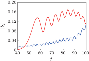
Figure  11 shows the pulse reflection calculated according to Eq. ( 35 ). Expression ( 35 ) is totally similar to the expression describing the reflection of a wave packet in the continuum case. Indeed, let Ψ ( x , t ) be a freely propagating wave packet, and let an infinitely high wall be placed at x L such that the wave function vanishes for x L . The needed solution Φ ( x , t ) is obvious: Φ ( x , t ) = Ψ ( x , t ) − Ψ (− x +2 L , t ), which is just the expression ( 35 ). In the discrete case, the amplitudes vanish for j = N +1.

Fig. 11. Reflection of the pulse from the lattice end. t = 75. Computation according to Eq. ( 35 ). Solid line is the reflected pulse, dotted line represents the tail of the incident pulse. At t = 75 the pulse leading edge, moving with v = 2, passed ≈ 150, lattice sites: 100 sites before reflection and 50 sites after reflection, MSRE < 10 −4 (numeric data are not shown), E = 1, C 2 = 0.5, N = 100.

At the instant t N the pulse leading edge returns to the lattice beginning and starts to interact with the donor. Amplitude a ( t ) increases. Our approximation concerning the smallness of a ( t ) becomes invalid. The system begins its return to the initial state. This process is analyzed in the next section.

6. Wave packet recurrence

Starting from the initial condition a ( t = 0) = 1 the pulse, having the well formed shape, spreads through the lattice with the velocity v = 2. If the lattice consists of N sites, then the time of the first returning to the donor is t N . The cycle of k recurrences takes time t kN . We solve the Eq. ( 9 ) with the kernel given by Eq. ( 10 ) to find a ( t ) at any time within arbitrary recurrence cycle k . The solution is searched in the form of the expansion in terms of partial amplitudes a k ( t ). The condition is imposed that each of amplitudes a k ( t ) is negligible in the time range t kN and its contribution to the total amplitude a ( t ) becomes essential only starting from times t kN , i.e., after the k -th recurrence.

In order to make sure in this kind of possibility, the kernel B N ( t ) (Eq. ( 10 )) is transformed according to the Poisson summation formula

where

We emphasize that B m ( t ) is the real function and recall that there exists the explicit expression for m = 0 through Bessel functions

Afterwards the original Eq. ( 9 ) with regard to transformation ( 36 ) takes the form

Note an important and useful property of functions B m : every function B m ( t ) is small in the time range 0 < t < mN , such that

With a reasonable degree of accuracy one can say that the function B m ( t ) ≈ 0 when t < mN . Consequently, when t < mN , then only terms B k with indices k < m give an essential contributions to Eq. ( 38 ).

Now we represent amplitude a ( t ) as the sum of partial amplitudes

Recall that the assumption concerning amplitudes a k ( t ) is based on the fact that amplitudes a k ( t ) are small at t < kN . To some extent a k ( t ) behaves like B k ( t ). Deriving an equation for a k ( t ) we assume that its right-hand side contains only terms B m ( t ) with m k .

Prior to writing down an equation for a k ( t ), we make one comment. Terms B m ( t ) are small (even for not too long lattices). This smallness is ensured by the fact that B m ( t ) = B m (− t ), and B m ( t ) ∼ ( mN ) −3 in the considered time range ( t > 0). Nevertheless terms with negative indices m are taken into account as their accounting allows one to derive explicit analytical formulaes.

We introduce functions m ( t ) to account for the contributions from B m ( t ) ( m < 0)

and we set 0 ( t ) ≡ B 0 ( t ) for the uniformity of notations.

Now in accordance with our assumptions, we convert Eq. ( 38 ) in a system of cycling equations for partial amplitudes a k ( t ). The equation for a 0 ( t ) contains only function 0 ( t ) in the right-hand side (see Eq. ( 37 ))

and taking into account the above-mentioned arguments, an equation for a k ( t ) ( k > 0) can be rewritten

It is important to note that system ( 43 ) is exact.

The Laplace transformation of Eq. ( 42 ) gives the following expression for a 0 ( p ):

Here, 0 ( p ) is the Laplace transform of B 0 ( t )

Expression ( 44 ) is nothing else but the amplitude a ( t ) in the semi-infinite lattice when there are no reflections (see Section 3).

The Laplace transformation of system ( 43 ) gives the algebraic system of recurrence relationships for a k ( p ) ( k > 0)

The Laplace transform m ( p ) of the function m ( t ) is given by the integral

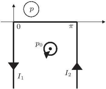
An explicit form of this integral can be obtained. With this aim in view, the integration contour is deformed as shown in Fig.  12 . As the integrand in Eq. ( 47 ) has period π , integrals I 1 and I 2 are cancelled as they have opposite integration paths. Consequently m ( p ) is defined only by the pole contribution at the point y 0 (cos( y 0 ) = i p /2). Then we have

Due to the fact that m ( p ) forms the geometrical progression by m , it is possible to make an explicit summation in recurrence formulaes ( 46 ). This is the main reason why the total amplitude a ( t ) can be represented in the form of the closed expression (see Appendix D).

Fig. 12. The integration along the path [0, π ] in expression ( 47 ) is changed to the residue in the pole p 0 and two integrals I 1 and I 2 .

The Laplace transforms of the partial amplitudes a k ( p ) ( k > 0) are expressed as

To get explicit expressions for the partial amplitudes, the inverse Laplace transform is made. Transforming the Laplace integral to the integration path around the cut [−2i, 2i], one gets an expression for a 0 ( t )

Further on, we get expressions for partial amplitudes a k ( t ) as

Here, the Laplace transform for a 0 ( p ) is performed at p = i x . An analysis of the expression for a k ( t ) shows that, as supposed, a k ( t ) ≪ 1 when t < ( k + 1) N .

Therefore, if the partial sum a 0 + a 1 + ··· + a k is taken for the representation of amplitude a ( t ), then the error of such approximation is of the same order as the smallness of k ( t ), i.e., ∼ [( k + 1)( N + 1)] −3 .

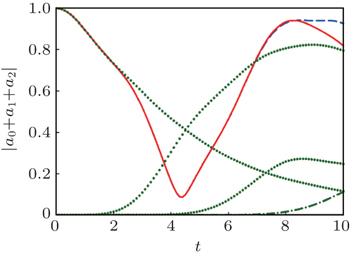
Fig. 13. The comparison of partial amplitudes sum | a 0 | + | a 1 | + | a 2 | (solid line) with the numeric integration (dashed line). Dotted lines: partial amplitudes | a 0 |, | a 1 |, | a 2 | “starting” at times t = 0, 2, 4, correspondingly. A small divergence is observed only at t > 8 where the unaccounted partial amplitude | a 4 | (dash-dotted line) starts to contribute. Parameters: N = 2, E = 1, C = 0.5, MSRE ≲ 10 −4 .

Consider as an example, the most unfavorable case of a very short lattice ( N = 2), and as an approximation, the sum of only three partial amplitudes a 0 + a 1 + a 2 . In Fig.  13 this partial sum is compared with the exact result of the numeric integration of the system ( 4 ). For t < 8 the expected error is ∼ 5 × 10 −5 . Thus the representation of a ( t ) by the sum of partial amplitudes is a very good approximation even for short lattices (the accuracy increases if the lattice becomes longer).

7. Multiple returning to the initial state

If the lattice is long enough then partial amplitudes, following each other, have enough time for damping on the corresponding time ranges [ t , t + N ]. In this case partial amplitudes do not interfere and reproduce the total amplitude with very high accuracy (see Fig.  1 ). The maxima of returning amplitudes slowly decrease.

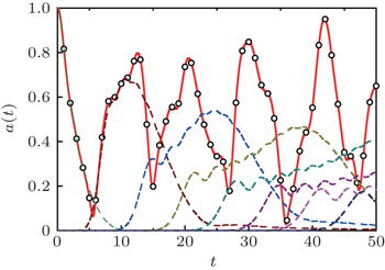
Partial amplitudes interfere on short lattices and maxima of returning amplitudes are irregular. The dependence of the total amplitude a ( t ) versus time for the lattice with N = 10 is shown in Fig.  14 . Numeric analysis performed at different values of parameters C , E , and N shows, that the maximal value of returned amplitude is a max ≈ 0.972 at t = 42 for N = 10.

Fig. 14. Solid line: sum of partial amplitudes | a 0 ( t )| + | a 1 ( t )| + ··· + | a 8 ( t )|. Dashed lines: partial amplitudes | a 0 |, | a 1 |, …, | a 8 | starting approximately at time instants t k = ( N /2) k = 5 k , k = 0, 1, …, 8. Maximal value of returned amplitude is ≈ 0.97 at t = 42. Empty circles: numeric results, MSRE ≲ 10 −5 . Parameters: N = 10, E = 0, C 2 = 0.4.

Incident and reflected pulses interfere on short lattices and the degree of returning is difficult to analyze at arbitrary parameter values C , E , N , but the first returning (maximal value of the partial amplitude a 1 ( t )) can be treated analytically if the lattice is long enough when the amplitude a 0 ( t ) becomes negligible.

The expression ( 51 ) for a 1 ( t ) using the trigonometric substitution of variables can be rewritten as

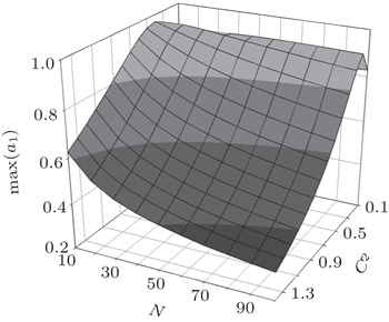
Figure  15 shows the maximal values of amplitude | a 1 ( t )| calculated according to Eq. ( 52 ) at E = 0 and different values of parameters N and C . One can notice that if C 2 ≈ 0.2 then the returned amplitude practically does not depend on the lattice length (10 < N < 100). The dissimilarity of the partial amplitude a 1 ( t ) from the total amplitude a ( t ) is negligible on this time range ( N < t < 2 N ). The divergence becomes essential (∼15%) for the shortest of considered lattices ( N = 10) and the smallest value of parameter C ( C 2 = 0.1). Amplitude a 0 ( t ) has not enough time to fully decay at these parameters values, and interferences with a 1 ( t ).

Fig. 15. Maximal value of amplitude of the first returning a 1 ( t ) at E = 0 and different values of C and N .
8. Conclusions

The wave function pulse, responsible for the charge propagation through the lattice, moves starting from the donor at the lattice end. If the electronic excitation is totally localized on the donor then, depending on the donor parameters, few scenarios of the quantum dynamics are realized. One of the most common cases is the formation of a pulse and its spreading through the lattice. The pulse moves with the maximal group velocity v = 2 and has the steep leading edge. The pulse amplitude decreases ∝ t −1/3 and the width increases ∝ t 1/3 . After reaching the opposite lattice end, the pulse reflects and moves in the opposite direction. This process can repeat many times.

The other scenario is realized if the parameters of the donor are such that the bound state is formed. Then the wave function is partially captured by this bound state. The analytical expressions describing the impulse dynamics coincide with the accurate numeric simulation with high precision.

There are several functions which describe the charge transfer employing the wave packet amplitudes b j ( t ). These include the first: and second: moments, and mean squared displacement , where 〈 n ( t )〉 = ∑ j j | b j ( t )| 2 . [ 20 ]

Different dependencies for probabilities and velocities of the pulse spreading are obtained as functions of the models used, and their parameters. Usually the dependence M 2 ( t ) ∝ t β is fulfilled. The power index β falls within the range 0 < β ≤ 2. The ballistic transport ( β = 2) is realized in the considered case of the defect-free lattice. If the lattice has the diagonal or/and off-diagonal disorder, then β < 2 and one or the other diffusion behavior is observed. Unusual hyperdiffusion cases when β > 2 are also known. [ 41 , 42 ] The second moment M 2 ( t ) is mostly calculated numerically, integrating the system similar to Eq. ( 4 ). Functions M 2 ( t ) and σ ( t ) can be calculated explicitly as there exist analytical representations for wave function amplitudes b j ( t ) in the present paper.

The problem of the electronic excitation spreading through the lattice formulated in a rather simple form, can be relevant to recent experiments on the charge transfer in synthetic olygonucleotides, polypeptides, and other non-metallic systems. At one time, it seemed that the polaron mechanism can adequately explain the charge transport in such substances. [ 43 50 ]

However, at least two weak points in the polaronic paradigm exist. First, polaron formation. After a charge is transferred to the chain, it should be more or less localized for some time allowing the polaron formation. The characteristic “dynamical” time of the lattice rearrangement is approximately two orders of magnitude greater compared to the “quantum” time (∼ ħ / ξ ); k , m are lattice rigidity and the mass of a particle, and ξ , intersite coupling. Otherwise, as is observed in numerical simulations, the wave function spreads very fast and approximately homogeneously along the lattice. The reason is that the lattice has not enough time for self-arranging and the polaron has no time for self-trapping. Most of the previous studies considered the polaron evolution on lattices with different interaction potentials when a polaron was created “by hand” as an initial condition. Unfortunately, too little attention was paid to the mechanisms of polaron formation.

The second problem is how the polaron can get an initial momentum necessary for the coherent movement. The initially formed unmovable polaron can start to move randomly (one-dimensional random walk) only under the influence of thermal fluctuations. Its diffusive movement cannot explain the experimentally observed single-step coherent transport. [ 9 ] As to our best knowledge, there exists the unique mechanism obeying the movement: When the next-to-nearest-neighbour interactions are included, for physical values of the parameters, polarons can spontaneously move, at T = 0, on bent chains that exhibit a positive gradient in their curvature. [ 51 ]

The discussed mechanism of quantum dynamical charge transfer allows one to exclude these difficulties in explaining the highly efficient charge transfer over long distances: the electronic wave packet, responsible for the charge transport, spontaneously forms and moves.

It is worth noting that results derived above for the defect-free lattices are also valid for weakly disordered systems. It was numerically verified that the pulse, travelling through the lattice N = 200 with the diagonal disorder W = 1, preserves its shape with rather good accuracy and is well approximated by Eq. ( 27 ).

Reference
1 Eberhard S Finazzi G Wollmann F A 2008 Annu. Rev. Genet. 42 463
2 Burda K 2007 Cell Biochem. Biophys. 47 271
3 Ferreira K N Iverson T M Maghlaoui K Barber J Iwata S 2004 Science 303 1831
4 Loll B Kern J Saenger W Zouni A Biesiadka J 2005 Nature 438 1040
5 Rich P R 2003 Biochem. Soc. Trans. 31 1095
6 Verkhovskaya M L Belevich N Euro L Wikström M Verkhofsky M 2008 Proc. Natl. Acad. Sci. USA 105 3763
7 Augustyn K E Genereux J C Barton J K 2007 Angew. Chem. Int. Ed. 46 5731
8 Barton J K Olmon E D Sontz P A 2011 Coord. Chem. Rev. 255 619
9 Genereux J C Barton J K 2010 Chem. Rev. 110 1642
10 Mallajosyula S S Pati S K 2010 J. Phys. Chem. Lett. 1 1881
11 Giese B 2002 Annu. Rev. Biochem. 71 51
12 Slater C Koster G F 1954 Phys. Rev. 94 1498
13 Anderson P W 1958 Phys. Rev. 109 1492
14 Biswas P Cain P Römer R A Schreiber M 2000 arXiv:cond-mat/0001315[cond-mat.dis-nn]
15 Kantelhardt J W Berkovits R Havlin S Bunde A 1999 Physica A 266 461
16 Kohmoto M Sutherland B Tang C 1987 Phys. Rev. B 35 1020
17 Ludlam J J Taraskin S N Elliott S R 2003 Phys. Rev. B 67 122203
18 Milde F Römer R A Schreiber M 1997 Phys. Rev. B 55 9463
19 Flach S 2010 Chem. Phys. 375 548
20 de Moura F A B F Caetano R A Santos B 2012 J. Phys.: Condens. Matter 24 245401
21 Evangelou S N Pichard J L 2000 Phys. Rev. Lett. 84 1643
22 Ng G S Kottos T 2007 Phys. Rev. B 75 205120
23 Ketzmerick R Kruse K Kraut S Geisel T 1997 Phys. Rev. Lett. 79 1959
24 Zhong J Diener R B Steck D A Oskay W H Raizen M G Plummer E W Zhang Z Niu Q 2001 Phys. Rev. Lett. 86 2485
25 Fermi E Pasta J Ulam S 1955 Los Alamos report LA-1940 (reprinted in Collected Papers of Enrico Fermi Segre E Vol. II, 1965, University of Chicago Press, 978
26 Berman G P Izrailev F M 2005 Chaos 15 015104
27 Ovchinnikov A A Erikhman N S Pronin K A 2001 Vibrational-Rotational Excitations in Nonlinear Molecular Systems New York Kluwer Acedemic/Plenum Publishers 298
28 Zwanzig R 1960 Lect. Theor. Phys. 3 106
29 Benderskii V A Falkovsky L A Kats E I 2007 JETP Lett. 86 221
30 Likhachev V N Astakhova T Y Vinogradov G A 2014 Theor. Math. Physics 180 1086
31 Benderskii V A Kotkin A S Rubtsov I V Kats E I 2013 JETP Lett. 98 219
32 Benderskii V A Kats E I 2011 JETP Lett. 94 459
33 Ndawana M L Römer R A Schreiber M 2002 Eur. Phys. J. B 27 399
34 Deych L I Lisyansky A A Altshuler B L 2001 Phys. Rev. B 64 224202
35 MacKinnon A Kramer B 1983 Z. Phys. B-Condens. Matter 53 1
36 MacKinnon A 1994 J. Phys.: Condens. Matter 6 2511
37 Pichard J L Sarma G 1981 J. Phys. C: Solid State Phys. 14 L127
38 Pichard J L Sarma G 1981 J. Phys. C: Solid State Phys. 14 L617
39 Elias B Genereux J C Barton J K 2008 Angew. Chem. Int. Ed. 47 9067
40 Gradstein I S Ryzhik I M 2007 Table of Integrals, Series, and Products 7th edn.) (Amsterdam Elsevier
41 Hufnagel L Ketzmerick R Kottos T Geisel T 2001 Phys. Rev. E 64 012301
42 Zhang Z Tong P Gong J Li B 2012 Phys. Rev. Lett. 108 070603
43 Conwell E M Rakhmanova S V 2000 Proc. Natl. Acad. Sci. USA 97 4556
44 Rakhmanova S V Conwell E M 2001 J. Phys. Chem. B 105 2056
45 Conwell E M Basko D M 2001 J. Am. Chem. Soc. 123 11441
46 Conwell E M Park J H Choi H Y 2005 J. Phys. Chem. B 109 9760
47 Conwell E M McLaughlin P M Bloch S M 2008 J. Phys. Chem. B 112 2268
48 Zhang G Hu H Cui S Lv Z 2010 Physica B 405 4382
49 Zhang G Cui P Wu J Liu C 2009 Physica B 404 1485
50 Wei J H Liu X J Berakdar J Yan Y 2008 J. Chem. Phys. 128 165101
51 Chakrabarti B Piette B M A G Zakrzewski W J 2012 EPL 97 47005