

High-efficiency wideband flat focusing reflector mediated by metasurfaces
[Yu Ji-Baoa) , Ma Hua†a)  , Wang Jia-Fu
a) , Li Yong-Fenga) , Feng Ming-Dea), b) , Qu Shao-Bo‡a) ]
, Wang Jia-Fu]
|
|


†Corresponding author. E-mail: mahuar@163.com
‡Corresponding author. E-mail: qushaobo@mail.xjtu.edu.cn
*Project supported by the National Natural Science Foundation of China (Grant Nos. 61331005, 11274389, and 11204378), the Postdoctoral Science Foundation of China (Grant Nos. 2013M532131 and 2014M552451), and the Foundation of the Author of National Excellent Doctoral Dissertation of China (Grant No. 201242).
We propose to achieve a high-efficiency wideband flat focusing reflector using metasurfaces. To obtain the wide band, the polarization conversion mechanism is introduced into the reflector design, based on the fact that the reflection phases of cross-polarized waves are linear in quite a wide band. This facilitates the design of wideband parabolic reflection phase profile. As an example, we design two reflective focusing metasurfaces with one- and two-dimensional in-plane parabolic reflection phase profiles based on elliptical split ring resonators (ESRRs). Both the simulation and experiment verify the wideband focusing performance in 10.0–22.0 GHz of the flat reflectors. Due to the wide operating band, such reflectors have important application values in communication, detection, measurement, imaging, etc.
Recently, metasurfaces with surface phase discontinuity were put forward, which attracted a great deal of attention.[1] Metasurfaces can manipulate and control electromagnetic waves on a sub-wavelength scale, resulting in many important applications including anomalous reflection/refraction, [1– 3] waveform transformation, [4] polarization conversion, [5, 6] flat lenses, [7– 10] surface wave coupling, [11, 12] etc. By choosing different sizes or rotating different angles of a resonator, one can arrange these resonators on a dielectric substrate with parabolic phase profiles to achieve wavefront focusing.[13– 15]
However, there are still two problems in front of us. Firstly, obtaining parabolic phase gradient with low polarization conversion efficiency results in low efficiency of focusing. Generally, multilayer metasurfaces can improve the polarization conversion efficiency and increase focusing energy density, but it is at the expense of increasing the size and weight.[16] Secondly, the previously focusing metasurfaces meet the parabolic phase gradient only in a very narrow bandwidth, which results in narrow-band focusing.[9, 17] Although wideband focusing metasurfaces can be obtained easily for circularly polarized waves, [18, 19] linearly polarized focusing is difficult to achieve a wide band, which restricts the practical application of focusing metasurfaces.
Motivated by linear reflection phases of cross-polarized waves, we obtain parabolic reflection phase profiles with high efficiency of cross-polarization in quite a wide band. Two thin polarized focusing reflectors are designed by arraying diverse geometry of ESRRs on dielectric substrates in this paper. The metasurfaces can rotate polarization state by 90° for linearly polarized waves. They can achieve high-efficiency focusing at wideband ranging from 10.0 to 22.0 GHz. The focal length varying with frequency and the focusing efficiency varying with incidence angles are also analyzed.
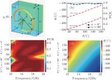
The unit cell of the proposed metasurfaces is shown in Fig. 1(a). It consists of an upper ESRR, metal background, and the middle dielectric substrate. The ESRR tilting 45° attaches to the dielectric substrate. Their axial ratio is 0.85, half long axis rm = 2.454 mm, line width w = 0.21 mm, and thickness t = 0.017 mm. The angle between the bisector of the ESRR’ s opening flare angle and the u axis is α (α = 0° and α = 90° ). The length of the dielectric substrate is a = 5.568 mm, the thickness is d = 2.5 mm, and its material is F4B-2 (ɛ r= 2.65, tan δ = 0.001).
By changing the opening flare angle, it is easy to adjust the phases of cross-polarized reflection waves. Figure 1(b) shows that the phases and polarization conversion ratio 
 | Fig. 1. (a) Schematic of the metasurfaces unit cell; (b) cross-polarization reflection phase Φ and PCR vary with θ at 14.5 GHz; (c) and (d) PCR and reflection phase Φ of the cross-polarized waves vary with flare angles. |
In fact, the PCR and phases of cross-polarization reflection waves meet the above requirements not only around 14.5 GHz, but also from 10.0 GHz to 22.0 GHz, as shown in Figs. 1(c) and 1(d). The efficiency of the cross-polarization is quite large. The reflection phase gradient is nearly dispersionless, and able to cover 360° for every frequency ranging from 10.0 GHz to 22.0 GHz, which ensures wideband wavefront focusing.
A conventional paraboloid reflects the incident electromagnetic waves on the surface at different positions to intersect at a point or line, and constructively interfere with each other. To realize reflective focusing over a flat reflector, different phase delays need to be settled on different positions of the reflector to make the reflective electromagnetic waves converge.
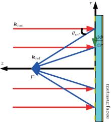
Suppose plane waves impinge on a flat reflector with a phase gradient ξ = dΦ /d r and the incident angle is θ inc. The in-plane wave number is k = ξ + kinc sinθ inc. Under normal incidences, the in-plane wave number is provided completely by the phase gradient, that is, k = ξ , as shown in Fig. 2. The inplane wave number of the reflected waves is k′ = kref · sinθ ref. According to the law of wave number conservation, there are kinc = kref and k = k′ , that is,

Combining with tanθ ref = r / F, the relationship among reflective phases, locations, and frequencies can be described as

where Φ 0 is the initial phase at the center of the metasurfaces, r is respect to the location on the surface, and F is the designed focal length. In a Cartesian space, the focusing reflector is called one-dimensional (1D) reflector if r2 = x2, and two-dimensional (2D) reflector if r2 = x2 + y2.
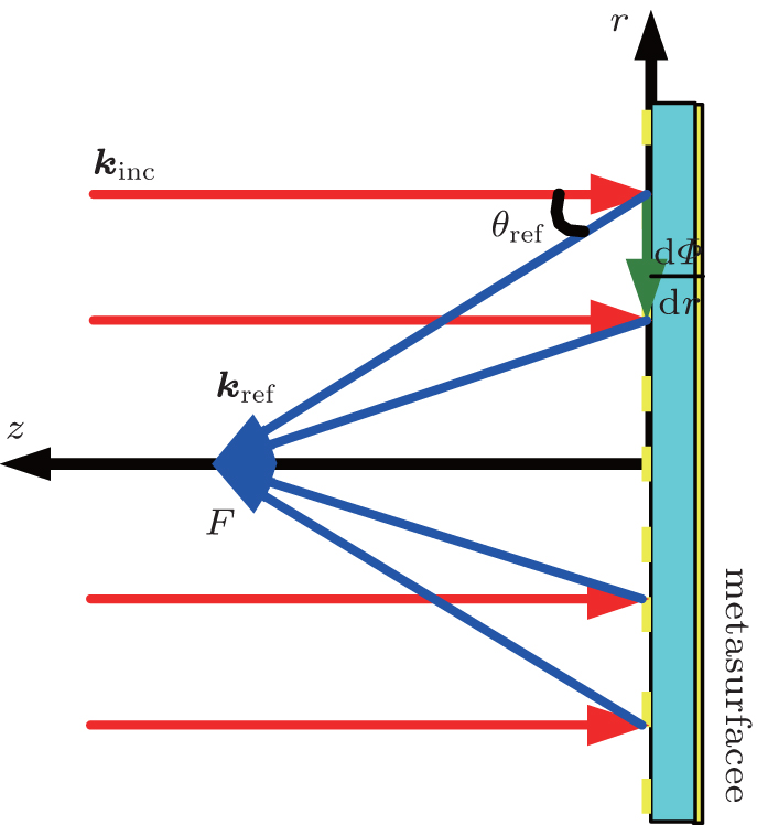 | Fig. 2. Schematic of focusing principle of a flat reflector. |
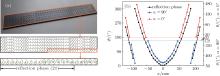
We arrange ESRRs with variant flare angles on the plate to construct a parabolic phase gradient according to Eq. (2). Figure 3(a) shows the fabricated sample in reflection geometry and its arrangement of unit cells. The upper photograph is the fabricated sample with size of 228.29 × 27.84 mm2, the middle schematic shows the ESRR array composed of 41 × 5 ESRRs, and the bottom schematic shows the super unit cell composed of 21 ESRRs. The parabolic phase gradient metasurface is arranged along the x axis, covering more than 2 × 360° of reflection phases, while it is repeatedly arranged along the y axis. The designed center frequency f0 is 14.5 GHz, the focal length F is 150 mm. The flare angle θ of the selected 41 ESRRs vary with the position x, and the corresponding cross-polarization field phases constitute a parabolic profile, as shown in Fig. 3(b). In addition, according to Ref. [3], two cross gratings covered on the front and back of the ESRR array make the metasurface functions in transmission geometry without influencing its performance.
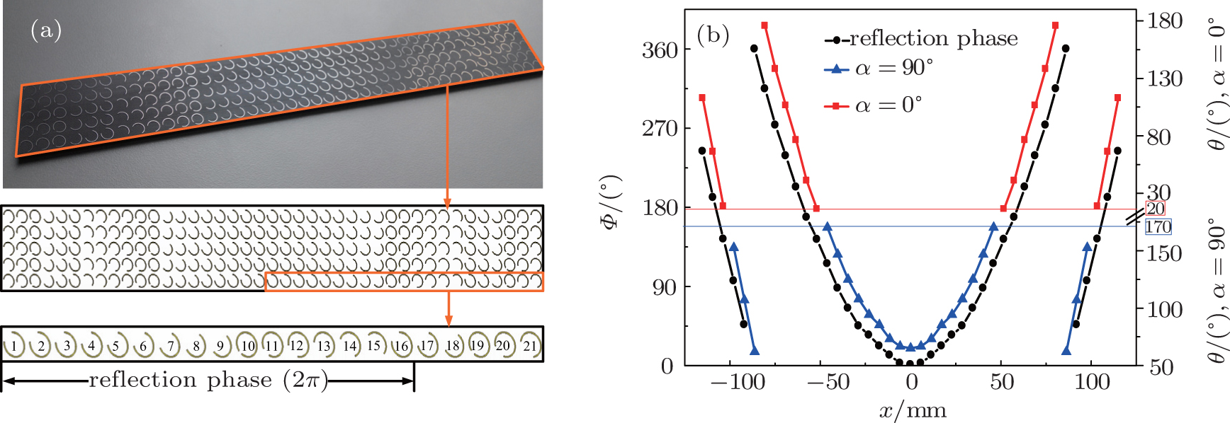 | Fig. 3. (a) Fabricated sample and schematics of the 1D reflector. (b) Cross-polarization reflection phase Φ and the flare angle θ vary with positions on the metasurface at 14.5 GHz. |
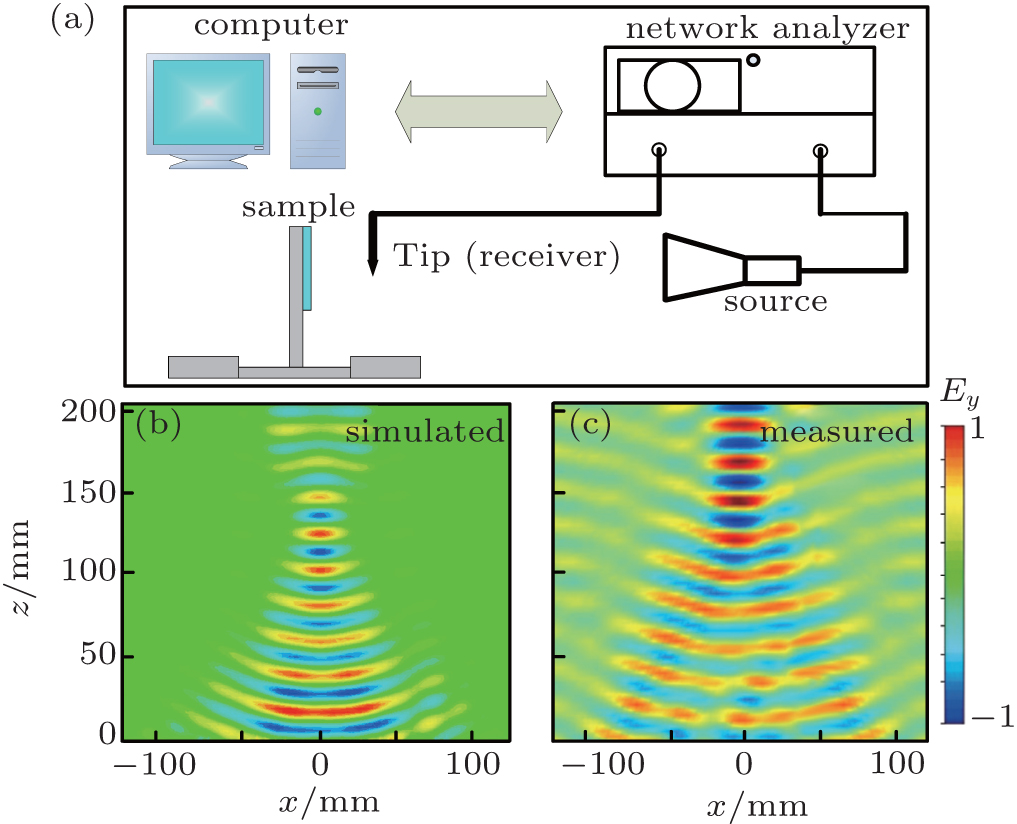 | Fig. 4. (a) Schematic of experimental system. (b) and (c) Simulated and measured distributions of y-component of reflection electric field at 14.5 GHz. |
Full-wave simulations are performed with CST Microwave Studio to verify the focusing property. The plane waves impinge on the metasurface normally with the electric field polarized along the x axis at 14.5 GHz. The distribution of the y-component of the reflection electric field is shown in Fig. 4(b). We built the experimental system shown in Fig. 4(a) to map the distribution of the reflected electric field in an anechoic chamber. The spatial resolution of the mapping is 2 mm, and the amplitudes of the electric field were recorded by a vector network analyzer. The measured result is shown in Fig. 4(c). The simulated focal length is about 148 mm, while the measured one is about 155 mm. The measured result is in agreement with both the design requirements and simulation results with a little bit of focal shift as a result of the finite size and measurement error.
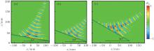
Moreover, the simulation results indicate that crosspolarization reflection waves are well focused to the focal line within a range of 10.0– 22.0 GHz, as shown in Fig. 5, while the co-polarization reflection waves are approximately zero. The focal length is about 115.4 mm, 130.8 mm, 152.8 mm, 175.3 mm, 199.5 mm, and 215.3 mm, corresponding to 11.0 GHz, 13.0 GHz, 15.0 GHz, 17.0 GHz, 19.0 GHz, and 21.0 GHz, respectively. We can find that the focal lengths increase with the incident field frequency, which can be applied to axial spectrometers and tunable Cassegrain antennas potentially. When frequencies do not fall in the range of 10.0– 22.0 GHz, the cross-polarization field still converges. However, due to decreasing PCR, the focusing effects deteriorate.
To further analyze the focusing properties of the metasurfaces, oblique incidence cases are considered. In the vicinity of the center frequency, cross-polarization field distributions at 10° , 20° , and 30° of incident angles are shown in Fig. 6. When the incident angle is less than 30° , the reflection waves
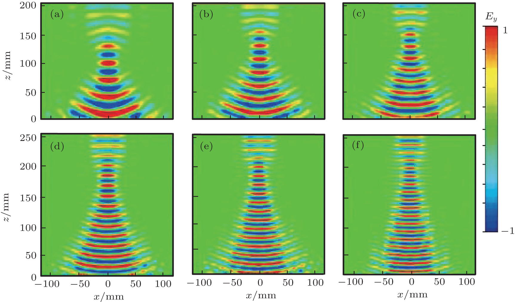 | Fig. 5. Distributions of the y-component of the reflection electric field at (a) 11.0 GHz, (b) 13.0 GHz, (c) 15.0 GHz, (d) 17.0 GHz, (e) 19.0 GHz, and (f) 21.0 GHz, respectively. |
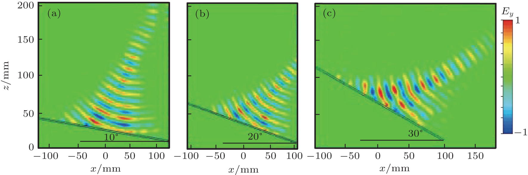 | Fig. 6. Distributions of the y-component of the reflection electric field at 14.5 GHz when the incident angle is (a) 10° , (b) 20° , and (c) 30° , respectively. |
are well converged to the focal line. Whereas when the incident angle exceeds 30° , the focusing effect deteriorates. This is due to the fact that the PCR decreases, and that the corresponding parabolic phase gradient changes under the condition of a large incident angle.
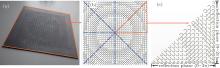
The phase gradient of a 2D flat reflector needs to be set in 2D space, and the design complexity is much bigger than that of a 1D reflector. We design a 2D parabolic phase gradient on a plate with size of 172.608 × 172.608 mm2, as shown in Fig. 7. Figure 7(a) is a photograph of the fabricated sample, figure 7(b) shows the schematic of the ESRR array consisting of 8 super unit cells which are symmetric about the diagonals and medians of the ESRR array, and figure 7(c) is the schematic of the super unit cell consisting of 136 ESRRs. The designed center frequency f0 is 14.5 GHz, and the focal length F is 150 mm.
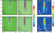
The cross-polarization electric field distributions and normalized field intensity (| Ey| 2/| E0| 2) at 14.5 GHz are shown in Fig. 8. The 2D phase gradient metasurface achieves polarization conversion and focusing. Measured (Figs. 8(b) and 8(e)) and simulation results (Figs. 8(a) and 8(d)) are in good consistency. As shown in Figs. 8(c) and 8(f), the center position of the focal spot is 158.3 mm, with a focal shift of 5.5%. The size of the focal spot along the horizontal orientation is about 28.3 mm and 29.8 mm in the x– o– z and y– o– z planes, respectively, which approaches Abbe’ s diffraction limit, 25.9 mm (0.6λ /NA). The axial ratio of the focal spot is 1.05, which approaches unity. Moreover, the relevance of focal length varying with the frequency is the same as that of a 1D metasurface.
 | Fig. 7. (a) A photograph of the fabricated metasurface; (b) schematic of the ESRRs array; (c) schematic of the super unit cell. |
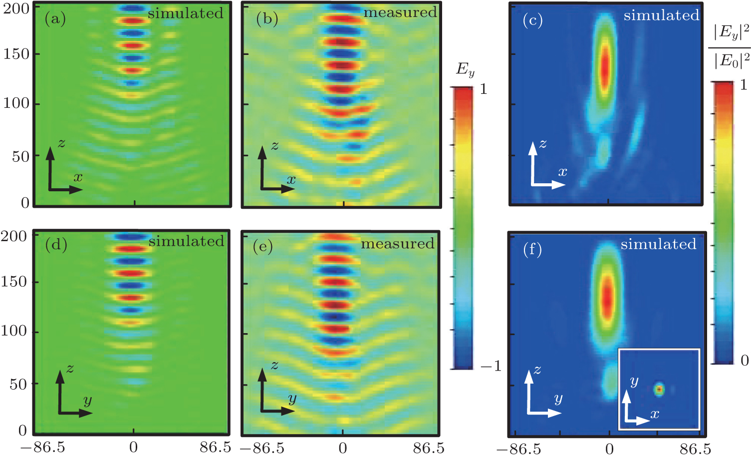 | Fig. 8. (a) and (b) Simulated and measured cross-polarization electric field distributions in the x– o– z plane at 14.5 GHz, respectively. (d) and (e) Simulated and measured cross-polarization electric field distributions in the y– o– z plane at 14.5 GHz, respectively. (c) and (f) Normalized cross-polarization electric field intensity in the x– o– z plane and y– o– z plane at 14.5 GHz, respectively. The inset shows the field intensity in the x– o– y plane at z = 158.3 mm. |
In conclusion, we demonstrated that ultrathin metasurfaces with 1D and 2D parabolic phase profiles can simultaneously polarization convert and focus with a high-efficiency and ultra-wideband performance in microwave frequency band. This work provides helpful guidance for manipulation and control of an electromagnetic wave in polarization state and propagation, and plays an important role in communication, detection, measurement, imaging, etc.
We acknowledge Cui Tie-Jun’s team at State Key Laboratory of Millimeter Waves, Southeast University for experimental support.
| 1 |
|
| 2 |
|
| 3 |
|
| 4 |
|
| 5 |
|
| 6 |
|
| 7 |
|
| 8 |
|
| 9 |
|
| 10 |
|
| 11 |
|
| 12 |
|
| 13 |
|
| 14 |
|
| 15 |
|
| 16 |
|
| 17 |
|
| 18 |
|
| 19 |
|