


Radial magnetic field in magnetic confinement device
[Xiong Haoa), b) , Liu Ming-Hai†a), b)  , Chen Ming
a), b) , Rao Boa), b) , Chen Jiea), b) , Chen Zhao-Quanc) , Xiao Jin-Shuia), b) , Hu Xi-Weia), b) ]
, Chen Ming|
|

 , Chen Ming
†Corresponding author. E-mail: mhliu@hust.edu.cn
*Project supported by the Special Domestic Program of ITER, China (Grant No. 2009GB105003).
The intrinsic radial magnetic field ( Br) in a tokamak is explored by the solution of the Grad–Shafranov equation in axisymmetric configurations through an expansion of the four terms of the magnetic surfaces. It can be inferred from the simulation results that at the core of the device, the tokamak should possess a three-dimensional magnetic field configuration, which could be reduced to a two-dimensional one when the radial position is greater than 0.6 a. The radial magnetic field and the amzimuthal magnetic field have the same order of magnitude at the core of the device. These results can offer a reference for the analysis of the plasma instability, the property of the core plasma, and the magnetic field measurement.
Tokamak-type devices are one of several types of magnetic confinement devices, and are one of the most promising candidates for producing controlled thermonuclear fusion. The total magnetic field in a tokamak is complex and of a helical shape, which is generated by the various coils’ currents and the electric current that flows inside the plasma. The toroial magnetic field is easily obtained in the coordinate system (R, φ , Z) as

the poloidal magnetic field is about 10− 3– 10− 2Bφ , and the radial magnetic field Br is commonly known as the error field which is generally considered to be majorly generated by the coil misalignments and the non-axisymmetric current. The radial magnetic field is relatively significantly smaller than the poloidal magnetic field, which can be neglected in most cases. However it plays a crucial role in instability analyses.
Rogers and his colleagues illustrated the importance of the radial magnetic field in the fast reconnection in a collisionless system depending on the dynamics of whistler and/or kinetic Alfvé n waves at small scales, where no quadratic waves can exist and the reconnection rate is very small when 
All of these viewpoints indicate that a very small Br is of great significance to the magnetic reconnection and the tearing mode in a tokamak. In the past, scholars used to think that the radial magnetic field Br was the error field generated by the coils’ misalignments and the non-axisymmetric current feeds. However, when calculating the magnetic field in the minor toroidal coordinate system (r, θ , φ ), it turns out that the intensity of the intrinsic radial magnetic field is equivalent to the azimuthal magnetic field at the core of the plasma (r < 0.2 a). Therefore, in this paper, the Grad– Shafranov equation is solved in the minor toroidal coordinate system, the results of numerical simulations show that there is a three-dimensional magnetic field structure at the core, and the radial magnetic field in the tokamak is considered to be produced by a combination of the intrinsic radial field and the error field.
The aim of this work is to calculate the magnetic field configuration in the minor toroidal coordinate system (r, θ , φ ), especially the intrinsic quantity of the radial magnetic field at the core of the plasma. As a result, it can offer a reference for the analysis of the plasma instability, the property of the core plasma, and the magnetic field measurement. The article is organized as follows. The physical model is presented in Section 2, followed by the simulation results in Section 3. The discussion and conclusion are presented in Section 4.
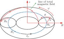
We solve the Grad– Shafranov equation in the minor toroidal coordinate system (r, θ , φ ), where r is the minor radial coordinate, φ is the toroidal angle, and θ is the azimuthal angle in the clockwise direction. Under the axisymmetrical hypothesis, the magnetic field is supposed to be independent of the toroidal angle φ .
Figure 1 is a diagram of the minor toroidal coordinate system. The quantitative relation between the minor toroidal coordinate system (r, θ , φ ) and the major toroidal coordinate system (R, φ , Z) is

The following is obtained through the Ampere law:


Equation (3) is the Grad– Shafranov equation in the minor toroidal coordinate system[16]

From Eqs. (1) and (2), the toroidal magnetic field should be revised when the angular current is considered.
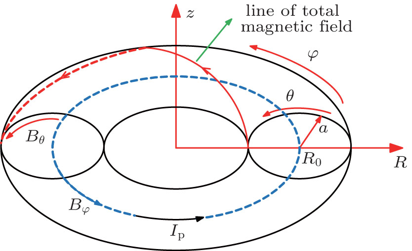 | Fig. 1. The minor toroidal coordinate system. |
The two-fluid modes regardless of impurity are


where mi and me are the masses of the ions and the electrons, respectively, ui and ue are their speeds; pi = nTi and pe = nTe are their pressures; Ti and Te are their temperatures; and τ ei is the collision time of ions and electrons.
The following is obtained by adding Eqs. (5) and (6) (nmi + nme ≈ nmi, the electron’ s inertia is neglected):

where p = pi + pe is the total pressure, and j = en(ui − ue) is the total current density.
The equilibrium equation in a steady state of no flow is

It can be seen that the three have similar shape distributions spatially.
The relations among the magnetic field, the magnetic surface, and the poloidal current I are defined as


The following is obtained by substituting Eqs. (8) and (10) to the radial component of Eq. (7):[17]

From the above formula, we can obtain

The following is obtained by substituting Eq. (13) to Eq. (4):

The magnetic surfaces are expanded to the 4th-order terms. Therefore, the initial value of the magnetic surface can be set as

where a0, a1, a2, a3 are the adjusting coefficients of the initial value of the magnetic surface.
The spatial distribution equations of pressure and current can be set as
where p0, A1, A2, I0, B1, B2 are the corresponding coefficients of pressure and current, respectively.
The central difference scheme is used for iteration for Eq. (4). For any point (ri, θ j),

The spatial step is 0.01 m, and the angle can be equally divided into 26 parts.
The boundary condition is eliminating the singularity around r = 0,

The boundary value can be obtained from Eq. (17) after the initial value of the magnetic surface is set. Through iteration by using the difference scheme of Eq. (14), the whole balancing magnetic surface distribution is obtained after some adjustments of a0, a1, a2, a3.
The magnetic field configuration is important for the takamak plasma. In the past, the magnetic surface of the tokamak plasma was solved in the magnetic surface coordinate (ψ , θ , φ ). Since the magnetic flux along the magnetic surface is irrelevant to the poloidal angle of the magnetic surface coordinate, the magnetic field in the magnetic surface coordinate system is equal to the two-dimensional spiral magnetic field, including only the poloidal magnetic field and the toroidal magnetic field. The position of every magnetic surface is difficult to identify and the shafranov displacement of every magnetic surface is not equal in the experiment. Therefore, when comparing the magnetic field data obtained in the magnetic surface coordinate and the experimental data, special attention should be paid to the difference between the position in the magnetic surface coordinate and the position in the spatial coordinate with the original point set at the device center.
However, in the minor toroidal coordinate system, the magnetic flux is a function concerning radius r and azimuthal angle θ ,

The three-dimensional magnetic field results can be obtained when solving the magnetic field of the tokamak plasma in the minor toroidal coordinate system, which includes the toroidal magnetic field, the azimuthal magnetic field, and the radial magnetic field (the radial direction centers at the original point of the minor radius coordinate system),
From the above, the source of the intrinsic radial magnetic field can be seen clearly.
In this paper, the azimuthal magnetic field is generated by the plasma current itself, thus the magnetic surface is also known as the net magnetic field. Shot number # 1026968 of J-TEXT serves as the calculation basis, and the major and minor radii of the device are 1.05 m and 0.27 m, respectively, the device belongs to a middle-sized circular section of the tokamak (formerly TEXT in Texas of the United States and was rebuilt by Huazhong University of Science and Technology in 2006).[18] The discharge parameters of the plasma are as follows: Bt = 1.60 T, Ip = 160 kA, ne0 ≅ 3.225 × 10¹⁹ m− 3, Te0 ≅ 0.9 keV, Ti0 ≅ 0.475 keV.
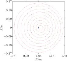
Figure 2 depicts the contours of the magnetic surfaces in the (R, Z) plane. The maximum of the Shafranov shift (shift of the magnetic axis) is 2.148 cm, which occurs at the innermost magnetic surface. This is the displacement of the magnetic axis. While the Shafranov shift of the outmost magnetic surface is almost zero, which means that the outmost magnetic field is in good agreement with the device.
 | Fig. 2. Contours of magnetic surfaces. |
Figure 3 depicts the Shafranov shift with different radius of the magnetic surface. The Shafranov shift is inversely proportional to the radius of the magnetic surface. The discrepancies between rs and r are especially cautious for the theoretical analysis, they are strictly equivalent only at the outermost position. Since the Shafranov shift at the core is large while the radius of the magnetic surface is small, the minor toroidal coordinate system reflects the furthest departure from the magnetic surface coordinate system in the center of the device. However, at the outermost part of the device, the minor toroidal coordinate system basically coincides with the magnetic surface coordinate system, mainly because the center of every magnetic surface is constantly changing. As the minor toroidal coordinate system deviates a lot from the magnetic surface coordinate system at the core, the specific magnetic surface structure is unknown during the process of experimental measurements and in fact the azimuthal magnetic field instead of the poloidal magnetic field is measured. Therefore, the three-dimensional magnetic field structure can provide a significant reference to the experimental magnetic measurement.
 | Fig. 3. Shafranov shift with different radius of the magnetic surface. |
In order to obtain a more accurate magnetic surface structure, the magnetic surface should be expanded to a higher order. In this way, the intrinsic radial magnetic field Br could be obtained. The perpendicular magnetic field is defined as 


 | Fig. 4. The vector graph of B⊥ . |
The radial magnetic field and the azimuthal magnetic field can be transferred to the poloidal magnetic field (Bp) and the magnetic field 
As shown in Fig. 5, the red circle is the magnetic surface at the core, and the dashed circle has its center at the geometric center and a radius of the radius of the magnetic surface.
 | Fig. 5. Magnetic surface coordinate and minor toroidal coordinate. |
The relationship between Br, Bθ and 


Thus the magnetic field structure can be obtained in the magnetic surface coordinate system. The magnetic field 
Through Eq. (18), the poloidal magnetic field and the magnetic field perpendicular to the magnetic surface in the magnetic surface coordinate system can be obtained based on the radial magnetic field and the azimuthal magnetic field in the minor toroidal coordinate system. Figure 6 depicts the relationship between the poloidal magnetic field and the radius of the magnetic surface. At the core, the poloidal magnetic field is significantly small. However, it increases rapidly with the increase of the radius of the magnetic surface and reaches its maximum value 0.135 T when the radius of the magnetic surface increases to 0.2 m (0.76a), and then slightly decreases with the increase of the radius. The variation range of the poloidal magnetic field is probably between 0.02 T and 0.135 T. The intensity of the magnetic field perpendicular to the magnetic surface is about 10− 4– 10− 2 of the poloidal magnetic field, therefore, it can be neglected compared to the poloidal magnetic field. That is to say, the magnetic field perpendicular to the magnetic surface is almost zero and the perpendicular magnetic field B⊥ is exactly the poloidal magnetic field. In the magnetic surface coordinate system, the magnetic field can be identified to have a two-dimensional structure. The results are identical to the magnetic field structure previously obtained in the magnetic surface coordinate system.
 | Fig. 6. Relation between the poloidal magnetic field and the raidus of the magnetic surface. |
Figure 7 is the changing law of the poloidal magnetic field with the change of the magnetic surface radius, where rs is 0.5a. From the above discussion, it is evident that the poloidal magnetic field at the strong field side is slightly larger than the poloidal magnetic field at the feeble field side, which is due to the toroidal effect.
 | Fig. 7. Relation between the poloidal magnetic field and the poloidal angle (rs = 0.5a). |
The Grad– Shafranov equation is solved in the minor radius coordinate system by an expansion of the four terms of the magnetic surface. In the past, the intrinsic radial magnetic field was often neglected, which was considered as the error field. However, in this paper, the intrinsic radial magnetic field is obtained by solving the Grad– Shafranov equation in the minor toroidal coordinate system. That is to say, the radial magnetic field in a tokamak is considered to be produced by a combination of the intrinsic radial field and the error field. The existence of the intrinsic Br has the following efficacies. 1) It can offer a reference for the analysis of the plasma instability such as sawtooths, tearing mode, etc. and the feature of the core plasma. 2) The first-order quantity of the magnetic field 

The first author is grateful to Prof. Yu of the Max-Planck-Institut für Plasmaphysik for his instructive remarks and suggestions. Appreciation is also expressed to Prof. Zhuang, Prof. Chen, Dr. Ding, Dr. Wang, Dr. Xu, Dr. Jiang, and Dr. Wang for their encouragement and useful advice.
| 1 |
|
| 2 |
|
| 3 |
|
| 4 |
|
| 5 |
|
| 6 |
|
| 7 |
|
| 8 |
|
| 9 |
|
| 10 |
|
| 11 |
|
| 12 |
|
| 13 |
|
| 14 |
|
| 15 |
|
| 16 |
|
| 17 |
|
| 18 |
|
| 19 |
|
| 20 |
|
| 21 |
|