†Corresponding author. E-mail: mvhuang@163.com
*Project supported by the National Natural Science Foundation of China (Grant No. 51406231).
The combustion of magnesium particles in water vapor is of interest for underwater propulsion and hydrogen production. In this work, the combustion process of a single magnesium particle in water vapor is studied both experimentally and theoretically. Combustion experiments are conducted in a combustor filled with motionless water vapor. Condensation of gas-phase magnesia on the particle surface is confirmed and gas-phase combustion flame characteristics are observed. With the help of an optical filter and a neutral optical attenuator, flame structures are captured and determined. Flame temperature profiles are measured by an infrared thermometer. Combustion residue is a porous oxide shell of disordered magnesia crystal, which may impose a certain influence on the diffusivity of gas phases. A simplified one-dimensional, spherically symmetric, quasi-steady combustion model is then developed. In this model, the condensation of gas-phase magnesia on the particle surface and its influence on the combustion process are included, and the Stefan problem on the particle surface is also taken into consideration. With the combustion model, the parameters of flame temperature, flame diameter, and the burning time of the particle are solved analytically under the experimental conditions. A reasonable agreement between the experimental and modeling results is demonstrated, and several features to improve the model are identified.
The combustion of magnesium particles with water is of interest for the hydrogen generation for fuel cells, which are considered as a potential renewable, clean fuel alternative for future energy supplies.[1, 2] The development of fuel cells requires the conception of a compact, safe, and inexpensive hydrogen source and storage systems. Magnesium has also been used as a fuel additive in many solid fuel propulsion systems due to its high energy density. One application in underwater propulsion is the water ramjet engine, which utilizes the highly exothermic combustion of powdered magnesium fuel and seawater to generate thrust.[3, 4] Without the oxidant onboard, water ramjet engines have the potential to improve specific impulses.
Extensive studies on the combustion of magnesium particles have been carried out for decades. In the early 1960s, the combustion of the magnesium droplet was first modeled by an extension of the quasi-steady vapor-phase diffusion flame theory for hydrocarbon droplets.[5] Based on that theory, the modeling of the magnesium particle combustion was gradually developed. In Ref. [6], a distributed two-dimensional mathematical model of magnesium particle combustion was established taking into account the region of the thermal influence of the particle on the gas. The single-phase Stefan problem was included in the magnesium particle combustion model in Ref. [7]. In Ref. [8], a simplified two reaction-zone model of the magnesium particle combustion in pure carbon dioxide was constructed, in which a vanishingly thin reaction zone, average transport properties across all regions, and neglect of the influence of C(s) and MgO(s) on the particle surface were assumed. In order to investigate the conditions required for the vapor phase combustion, the relationship between the heat fluxes in the combustion of a single magnesium particle in an oxygen-containing medium was analyzed. The results indicate that the vapor-state combustion is possible only in the case where a considerable portion of magnesium oxide condenses on the droplet surface.[9] Using the ab initio quantum chemical method, the reaction mechanism of Mg with water was investigated, [10] and a preliminary macro-kinetics model was developed in Ref. [11].
As for the experimental study, optical spectrum investigations have been applied to acquire component concentration and gas phase temperature distributions in the combustion zone of a single magnesium particle.[12] Similarly, the radiation bands of the Mg and MgO vapor were observed in the research on the magnesium particle combustion in air[13] and the aerosol combustion in microgravity.[14] The PLIF images obtained in Ref. [15] indicated that the magnesium combustion with oxygen at atmospheric pressure is a predominantly gas phase reaction and can be characterized as a quasi-steady process. In addition, experimental and numerical studies showed that the magnesium particle combustion in CO2 is also controlled by the vapor phase diffusion, [16] and a pulsating flame was observed in the experiment due to the formation of a carbon layer on the particle surface. An experiment on the combustion of a Mg/H2O(l) mixture was conducted in Ref. [17], and a diffusion-limited model for the combustion wave propagation in Mg/H2O(l) mixtures was developed and solved analytically. Investigations on the diffusion dominated reaction between magnesium particles and water vapor have been performed in Refs. [18] and [19]. A conclusion can be drawn from the above studies that magnesium particles have the ability to burn as the vapor phase diffusion flames.[20] However, without a clear understanding of the feedback mechanism between the metal-oxidation kinetics and structural features of the oxide film, it is difficult to construct a model that adequately describes magnesium ignition and combustion.[21]
As to the research on magnesium particle combustion with water vapor, little experimental data is available. Several problems have to be addressed in the experiments, for instance, creating an environment of pressurized water vapor, and fixing and igniting the small magnesium particles. Previously in our group, basic ignition and combustion characteristics of a single magnesium particle in water vapor were observed experimentally.[22] In the present study, the experiment is further refined, and then a mathematical model of single magnesium particle combustion in water vapor is developed. Comparisons between the model predictions and the experimental results are also performed.
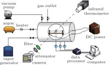
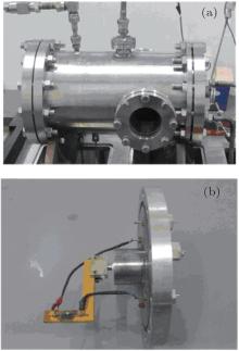
In order to study the combustion characteristics of magnesium particles with water vapor, an optical pressure vessel, a particle ignition device, and a gas pipeline system were designed, fabricated, and tested. Figure 1 is a schematic diagram of the experimental facility. Figure 2(a) shows a photograph of the optical pressure vessel, in which an environment of water vapor can be provided. The vessel was constructed from stainless steel and can sustain pressure of up to 4 MPa. It is equipped with two quartz windows having a Φ 80 mm field of view. The particle ignition device, as shown in Fig. 2(b), is positioned inside the pressure vessel during the tests, keeping the particle within the visible area by the optical windows. The tested magnesium particle is perforated by a chromel wire for fixing and heating, which is connected to an adjustable direct-current (DC) power outside through a plug at one end of the pressure vessel. For the gas pipeline system, water vapor is supplied by a vapor generator, providing a vapor pressure of 3.5 MPa, and a temperature of 553 K to the maximum. Argon is used for the dilution of the water vapor in the system.
With the decreasing vapor temperature caused by heat loss during the test, the water vapor inside the optical pressure vessel is apt to condense, which would lead to the vapor pressure dropping. In order to stabilize the vapor state, measures were taken to diminish the heat loss. Glass wool was applied to the outside of the vessel wall for heat insulation; before each test of the vessel, water vapor was repeatedly filled to preheat the pipeline and vessel walls. In this way, a vapor state above 423 K, 2.5 atm can be sustained during the particle combustion.
In the experiments, an infrared thermometer (MODLINE 5R-3015, IRCON) ranging from 1273 K to 3273 K, with an uncertainty of 0.5% Fs, was applied in order to measure the flame temperature of the magnesium particle combustion. A Ni– Cr thermocouple (Type-K, 0.5 mm in diameter) with an upper range of 1573 K was embedded into the specimen to obtain the particle temperature during the combustion process, and its uncertainty is ± 2.5 K. Due to the adequate particle combustion time, a digital camera with a sampling frequency of 25 fps was adopted for combustion observation, instead of using a high-speed camera. In addition, an optical filter (center wavelength 500 nm) and a neutral optical attenuator (transmission 0.1%), as shown in Fig. 3 were added at the front of the lens to distinguish the flame front from the luminous combustion zone. A thermocouple and a pressure transducer were installed at the combustor to measure the temperature and the pressure of the vapor environment. The pressure uncertainty is 0.1% FS, and the temperature uncertainty here is ± 5 K.
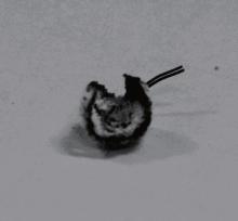
Experiments of single magnesium particle combustion in water vapor were conducted. The experimental parameters and results of two runs 1 and 2 are listed in Table 1. Figure 4 shows typical images of the flame characteristics of the vapor-phase combustion stage of an individual Mg particle in water vapor. After ignition, the evaporation mass rate of magnesium increases significantly and the flame expands rapidly, turning to the vapor-phase combustion stage at which the flame stays at a certain distance from the surface of the particle. With the help of an optical filter and an attenuator, the flame front and flame size could be determined. The luminous core surrounded by the flame is a near-spherical oxide layer. From the images in Fig. 4, a portion of the combustion product coagulating on the particle surface, which thickens the particle oxide layer, can be distinguished. From these results, it is inferred that the solid-phase MgO was formed at the particle surface.
| Table 1. Experimental results. |
 | Fig. 4. Images of Mg particle combustion in water vapor obtained by a camera at (a) t = 0.81 s, (b) t = 1.53 s, (c) t = 9.27 s, and (d) t = 11.63 s. Ignition time ti = 0. |
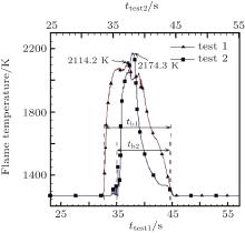
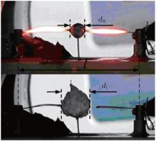
The flame temperature variation during the vapor-phase combustion in both experiments was recorded by an infrared thermometer. As shown in Fig. 5, the peak temperature is 2114.2 K and 2174.3 K, respectively. The measured flame temperatures are lower than the adiabatic value 2800 K, [23] owing to heat loss. According to Fig. 4(b) which was taken 1.53 s after the ignition, the distance between the two terminals (l) is 40 mm, and the particle flame diameter (df) is determined as 11.26 mm, as shown in Fig. 6.
Methods based on the recorded images and the temperature curves were employed respectively and then compared in order to obtain an appropriate particle burning time. At this point, the particle burning time refers to the vapor-phase combustion process. As for the recorded images, the burning is considered as the period from when the particle ignites until its luminous flame goes out, as shown in Figs. 7(a) and 7(b). With the temperature curves, the defined burning time begins when the temperature rises suddenly, and ends when it returns to the starting value, as shown in Fig. 5, tb1 and tb2 are the particle burning times of the two experiments.
As shown in Figs. 4(c) and 4(d), with the burning of the particle, the flame gradually shrank to the particle surface and died out in the end, leaving a near-spherical residue. The diameter of the residue was about twice the initial value, as shown in Fig. 8. Figure 9 is a photograph of the particle residue removed from the ignition device, which shows a hollow spherical shell shape of the residue. The black substance on the residue shell was cohered from the insulating bakelite board under the burning particle, which was ablated by the particle flame. The porous structure of the residue shell observed under the scanning electron microscope (SEM) is presented in Fig. 10. It was composed of disordered magnesia crystal with holes at different scales, as the arrows shown in Fig. 10. It was estimated that the size of the holes were from 10 μ m to 100 μ m. This structure of the residue shell would certainly exert an influence on the diffusivity of the gas components between the particle and the environment.
 | Fig. 10. SEM photograths of the oxide shell. |
Based on the combustion characteristics of single magnesium particles in water vapor observed in the experiments, a simplified model was developed for a basic understanding of the magnesium particle combustion process. As depicted in Fig. 11, the model consists of an internal zone, an external zone, and a thin flame surface between the two zones. In the internal zone, magnesium vapor diffuses outwards to the reaction surface and reacts with the water vapor coming from the external zone in a stoichiometric proportion. Gas-phase products diffuse from the flame surface to both sides, while condensed phase products move outwards with the bulk gas flow. Gas-phase magnesia in the products condenses when arriving at the particle surface. With the heat from the condensation of the magnesia and the thermal radiation of the flame surface, the melted particle evaporates into the gas phase, and furthermore the gas-phase magnesium is heated to the flame temperature. At the flame surface, both gas-phase and solid-phase MgO are produced, and the reaction of Mg and water vapor is written as

where a + b= 1.
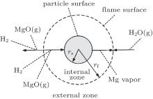 | Fig. 11. Sketch of the proposed model. |
Within this model, the following assumptions are also made for simplification.
(i) The flame surface is infinitely thin with no reaction occurring elsewhere.
(ii) The combustion process is quasi-steady and the flame is spherically symmetric.
(iii) Condensation rate of gas-phase MgO on the particle surface is infinite. The condensed MgO covers the particle evenly.
(iv) Gas– liquid equilibrium at the particle surface is assumed, and Clausius– Clapeyron equation is applied.
(v) Density-diffusivity product (ρ D), thermal conductivity (λ ), and heat capacity (cp) of the gas phase are considered to be constant, and the Lewis number equals 1. Here, ρ is the local gas-phase density, and D is the local gas-phase diffusivity.
In the present model, the effect of the porous oxide shell on the thermal conductivity of the magnesium particle is taken into consideration. Here, the shell is treated as a porous medium with pinholes, as shown in Fig. 12. An effective thermal conductivity (λ e) of the particle oxide shell is defined by λ e = α λ gas + (1 − α )λ MgO, where α is the porosity of the particle shell, λ gas is the thermal conductivity of the gas-phase medium, and λ MgO the thermal conductivity of MgO.
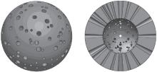 | Fig. 12. Postulated structure of oxide shell. |
Based on the assumptions above, the species mass conservation equations within the internal zone (rs ≤ r ≤ rf, where r is the local radius, rs is the particle radius, and rf is the flame radius) can be presented as


where ṁ 1 and ṁ 2 are the net mass flow rates in the internal zone and the external zone, respectively; YMg, YMgO, YH2 are the mass fractions of Mg vapor, gas-phase MgO, and hydrogen.
The gas-phase energy conservation equation within the internal zone is

where T is the local temperature.
The species mass conservation equations within the external zone (rf ≤ r ≤ ∞ ) can be described as


The gas-phase energy conservation equation within the external zone is

At the boundaries, when r = rs,


where Ts is the particle surface temperature, and YMg, s, YMgO, s are the mass fractions of Mg vapor and gas-phase MgO at the particle surface.
Considering the Stefan flow at the particle surface (r = rs), we obtain


where ṁ i, j is the mass flow rate of component i, which corresponds to the internal zone when subscript j = 1, and to the external zone when j = 2.
At the flame surface, magnesium vapor reacts with water vapor completely in a stoichiometric ratio. When r = rf,


where YMg, f, YMgO, f, YH2O, f, and YH2, f are the mass fractions of Mg vapor, gas-phase MgO, water vapor, and H2 at the flame surface. MMg, MH2O, and MH2 are the molecular weights of Mg, H2O, and H2.
According to the assumption of phase equilibrium, the mass fraction of Mg at the flame surface can be calculated with the Clausius– Clapeyron equation

where M̄ is the molecular weight of local gas-phase mixture, Lv is the evaporation latent heat of magnesium droplet, pref is the reference pressure, p is the pressure of local gas-phase mixture, Tref is the reference temperature, and R is the gas constant of magnesium vapor.
When r → ∞ ,


where YH2O, ∞ , YH2, ∞ , and YMgO ∞ are the mass fractions of each component in the environment, and T∞ is the temperature in the environment.
Calculate the integrals of Eqs. (1), (2), and (4) from rs to r, set r = rs, and then we obtain


where Tf is the flame temperature, qr is the heat transfer rates by radiation from the flame surface to the particle, and qc is the heat release rate by condensation of gas-phase MgO at the particle surface.
In a similar way, results of integrals of Eqs. (6)– (8) from rf to r with r = rf give


where σ is the Boltzmann constant, ε is the emissivity, and Qmg rate of reaction heat by Mg and H2O at the flame surface.
Moreover, the following equations are obtained according to the conservation of Mg atoms and mass at both zones across the flame surface:


where MMgO is the molecular weight of MgO.
Selecting Eqs. (17)– (20) and Eqs. (25)– (33), the mathematical model for a single Mg particle combustion in water vapor is established, and the unknown parameters are ṁ 1, ṁ Mg, 1, ṁ MgO, 1, ṁ 2, ṁ H2O, 2, ṁ H2, 2, ṁ MgO, 2, YMg, s, YMgO, f, YH2, fTs, Tf, rf.
With the model established above, calculations of the magnesium particle combustion in water vapor were conducted, and previous experimental conditions were used as input. According to SEM results, the porosity of the shell (α ) was estimated at 0.219, with which effective thermal conductivity was calculated. Boltzmann constant (σ ) is 5.67 × 10− 12 W/(cm2 · K4) and emissivity (ε ) used was 0.4.
The calculated results of single magnesium particle combustion under experimental conditions of Exp. 01 are presented in Figs. 13(a)– 13(c). Figure 13(a) shows the calculated evaporation mass rate and gas-phase MgO condensation mass rate of the magnesium particle. The particle evaporation mass rate also represents its combustion rate, and with the MgO condensation mass rate, the total mass of the solid-phase MgO at the end of combustion was determined as 0.0316 g. This value is less than the measured shell mass of 0.0457 g, which implies that surface reactions may take place during the particle combustion. The particle temperature stays around the magnesium boiling point, while the flame temperature varies with the particle radius as shown in Fig. 13(b). As seen in Fig. 13(c), the particle flame size is about twice the size of the particle all along the combustion.
 | Fig. 13. Calculated results of single magnesium particle combustion under experimental conditions of Exp. 01. (a) Evaporation rate versus r; (b) particle temperature versus t; (c) particle radius versus t. |
For a comparison between the experimental and calculated results, the calculation was set to stop at the time corresponding to Fig. 4(b) (t = 1.53 s). The calculated temperature and mass fraction distributions around the particle are presented in Figs. 14 and 15. Tables 2– 4 give the comparisons between the calculated and the experimental results in terms of the flame temperature, the flame diameter, and the burning time of the two tests.
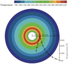 | Fig. 14. Temperature distribution around the particle at 1.53 s. |
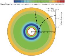 | Fig. 15. Mass fraction distribution of Mg and H2O around the particle at 1.53 s. |
| Table 2. Particle flame temperature comparison. |
| Table 3. Particle flame diameter comparison. |
| Table 4. Particle burning time comparison. |
As shown in Table 2, the experimental and calculated flame temperatures of the particles are close. However, the calculated particle flame diameters of both cases in Table 3 deviate significantly from the measured values, which are about 23% larger. This deviation could be caused by the assumption of a vanishingly thin reaction surface with no reaction occurring in both internal and external zones, as the surface reaction may take place during the combustion. Reaction dynamics in more detail should be included in order to improve the model. The particle burning time in this work was judged with recorded images and temperature curves, as shown in Table 4. In the present model, the influences of the porous oxide shell on the Mg droplet evaporation mass rate and gas phase diffusivity were neglected, resulting in a slightly shorter calculated burning time than the experimental results. Note that the particle burning time determined by the temperature curve in Case 2 is less than its calculated value. This is because the Mg particle was not fixed well by the wire in this test, and the particle dropped and deviated from the focus of the infrared thermometer, leading to a drastically decreased temperature.
The combustion of a single magnesium particle in a water vapor atmosphere has been experimentally investigated. The results have been successfully modeled using the real particle and gas properties. Based on the experimental measurements and the developed model, the following is concluded.
With an optical filter and a neutral optical attenuator, the gas-phase flame structure and the flame surface of the burning particle were captured. A portion of the combustion product was observed coagulating on the particle surface, from which it can be inferred that the solid-phase MgO formed on the particle surface. The lame temperature measured by an infrared thermometer is above 2100 K. The particle burning time determined by the recorded images and the temperature curves were compared. The diameter of the particle residue was about twice its initial value, and the residue took the shape of a hollow spherical shell. The characteristics of the particle oxide shell were analyzed using SEM. The oxide shell has a porous structure, which is composed of magnesia crystal bonded together disorderly with holes at different scales.
A one-dimensional, spherically symmetric, quasi-steady model was developed to describe a single magnesium particle burning in water vapor. In this model, condensation of the gas-phase MgO on the particle surface was considered, and the Stefan problem at the particle surface was included. The flame structure predicted by the model shows a temperature profile with a sharp peak at the flame surface, which is associated with the assumption of the thin reaction zone. A reasonable agreement between the model predictions and the experimental results on the flame temperature, the flame diameter and the burning time of the particle was obtained. The particle-surface reaction, the detailed reaction dynamics and the effect of the condensed MgO on the evaporation mass rate of a magnesium droplet should be considered to further improve the model accuracy.
| 1 |
|
| 2 |
|
| 3 |
|
| 4 |
|
| 5 |
|
| 6 |
|
| 7 |
|
| 8 |
|
| 9 |
|
| 10 |
|
| 11 |
|
| 12 |
|
| 13 |
|
| 14 |
|
| 15 |
|
| 16 |
|
| 17 |
|
| 18 |
|
| 19 |
|
| 20 |
|
| 21 |
|
| 22 |
|
| 23 |
|


