†Corresponding author. E-mail: jccao@mail.sim.ac.cn
*Project supported by the National Basic Research Program of China (Grant No. 2014CB339803), the National High Technology Research and Development Program of China (Grant No. 2011AA010205), the National Natural Science Foundation of China (Grant Nos. 61131006, 61321492, and 61404149), the Major National Development Project of Scientific Instrument and Equipment, China (Grant No. 2011YQ150021), the National Science and Technology Major Project, China (Grant No. 2011ZX02707), the Major Project, China (Grant No. YYYJ-1123-1), the International Collaboration and Innovation Program on High Mobility Materials Engineering of the Chinese Academy of Sciences, and the Shanghai Municipal Commission of Science and Technology, China (Grant Nos. 14530711300).
Terahertz quantum cascade lasers (THz QCLs) emitted at 4.4 THz are fabricated and characterized. An equivalent circuit model is established based on the five-level rate equations to describe their characteristics. In order to illustrate the capability of the model, the steady and dynamic performances of the fabricated THz QCLs are simulated by the model. Compared to the sophisticated numerical methods, the presented model has advantages of fast calculation and good compatibility with circuit simulation for system-level designs and optimizations. The validity of the model is verified by the experimental and numerical results.
The terahertz (THz) region (0.3– 10 THz) of the electromagnetic spectrum has attracted significant attention for its proved potential in a number of applications, such as remote sensing, communication, astronomy, biology, and medicine.[1] Since their first realization in 2002, [2] terahertz quantum cascade lasers (THz QCLs) operating in the frequency range from 1 THz to 5 THz have become promising candidates to supply intense THz light. When THz QCLs are used in communication and similar systems, a system-level simulation is highly desired for the circuit design and system performance optimization. Traditionally, the performance of THz QCLs can be described accurately by several numerical methods, such as the self-consistent rate equations model[3] and the non-equilibrium Green’ s function formalism.[4] However, these methods are not suited to the system-level designs since they have high computational cost and are incompatible with the circuit simulation and optimization.
Therefore, equivalent circuit models are developed for circuit simulation, which can be integrated with the readout circuit for system level design.[5] In this paper, THz QCLs with four-well resonant phonon (RP) active region structure are fabricated and an equivalent circuit model is constructed based on the five-level rate equations. Utilizing this model, the characteristics of the THz QCLs at steady and dynamic states are quickly obtained, which are in good agreement with the experimental and numerical results. By using the common circuit simulation tools, such as SPICE, the equivalent circuit model presented in this paper has advantages of fast calculation and good compatibility with the circuit simulation compared to other numerical methods.
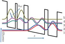
The RP active region structure of THz QCLs in Ref. [6] is utilized in this work and was grown in the GaAl/Al0.15Ga0.85 As material system by molecular beam epitaxy with 183 cascaded modules. Figure 1 shows the calculated wave functions and the conduction band structure of the considered devices calculated by self-consistent Poisson– Schrodinger equations[7] under the design bias of 11 kV/cm, indicating that the investigated devices are based on the five energy levels lasing structure.
The carrier transport and output characteristics of the devices can be described by the following five-level rate equations:


where η is the injection efficiency, I is the injection current, q is the electronic charge, N1, N2, N3, N4, and N5 are the numbers of carriers in the five levels, respectively, gc is the gain coefficient, S denotes the photon number, Γ is the confinement factor, τ 54, τ 53, τ 43, τ 42, τ 41, τ 32, τ 31, and τ 21 are the lifetimes representing the transitions between the corresponding levels, τ 5, τ 4, and τ 3 are the total lifetimes of the corresponding levels, τ tunnel denotes the tunneling rate, c is the velocity of light, n is the effective refractive index of the device, α denotes the total optical loss, τ sp is the spontaneous lifetime, τ pn is the photon lifetime, and β stands for the spontaneous emission coupling coefficient.
The equivalent circuit model consisting of six sub-circuits is extracted according to Eqs. (1)– (6) by considering N5, N4, N3, N2, N1, and S as the voltages of the nodes in the corresponding sub-circuits. For example, the revised form of Eq. (1) can be written as

As shown in Fig. 2, equation (7) can be interpreted as a Kirchoff’ s current law equation when the q term is considered as a capacitor, τ 5/q as a resistor, qΓ (c/n)gc(N5 – N4)S and I as the current sources controlled by the node voltages of the sub-circuits and the current of the biased device, respectively. By employing similar procedures, the equivalent circuit model of the THz QCLs is constructed, which can be analyzed accurately and quickly by circuit simulation tools, such as SPICE.
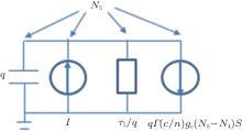 | Fig. 2. The equivalent circuit extracted from Eq. (1), where carrier number N5 is considered as the node voltage of the sub-circuit. |
The current-voltage (I– V) characteristic of the THz QCLs is modeled by a diode with a series resistance. The parameters in the model are obtained by fitting the measured data with the expression

where VT is the thermal voltage, Is is the reverse saturation current of the diode, and Rs is the series resistance. The following expression is used to calculate the gain coefficient used in Eqs. (1), (2), and (6):

where Δ N is the population inversion, f0 is the resonance frequency of the transition, | d| is the dipole matrix element, ħ is the reduced Planck constant, ε 0 is the permittivity of free space, and L(f) is the Lorentz-type line shape.
The lifetimes of carriers on different energy levels in Eqs. (1)– (6) are derived from the Monte Carlo (MC) simulation. Electron– electron, electron– LO-phonon, electron– impurity scatterings and the hot-phonon effect are included in the MC model used here. Details are available in our previous work.[8– 11]
In order to construct the circuit model, the relation between the optical output power P and the photon number S is used

where L is the length of the laser cavity, and R is the facet reflectivity.
The devices are fabricated as follows. The 160 μ m-wide ridge was defined by optical lithography and dry etching. Ti/Au metallization was applied as the top contact. After thinning down the substrate to about 150 μ m, a 3-mm long laser bar was cleaved, then the device was soldered onto a Cu heat sink and wire-bonded for measurements. The top view of the devices is shown in the inset of Fig. 3. For measurement, the THz QCL was mounted on the cold finger of a closed-cycle helium cryostat with a polyethene window. The detailed description of the measurement setup can be found in our previous work.[12, 13]
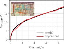 | Fig. 3. Comparison between the experimental THz QCL current– voltage curve at 10 K and the result fitted by Eq. (7). Inset is the top view of the fabricated THz QCLs. |
The best fitting result of the I– V characteristic based on Eq. (7) is shown in Fig. 3. It can be seen that with a series resistance about 1.519 Ω , the result obtained by the diode model agrees well with the experimental one.
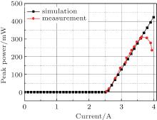
Figure 4 depicts the output light power– current (P– I) characteristic of a 160 μ m wide and 1 mm long THz QCL sample at the heat sink temperature of 10 K in the pulsed mode. The driven current of the sample has a repetition rate of 2 kHz and a pulse width of 5 μ s (1% duty cycle). The peak power of the sample is about 300 mW, and the threshold current is about 2.5 A. As the injected current increases, the temperature increases, and the sample is saturated due to the variation of temperature dependent carrier lifetime and other thermal effects which decrease the population inversion. The P– I behavior of the sample is well described by the model as shown in Fig. 4. It should be noted that because the characteristic of the devices in the quasi linear area of the P– I curve is important for practical applications, and differences between parameters such as carrier life times in this area are rather small, we only use parameters calculated for the devices under 3 A in the simulation. This is why the derivation exists between simulation and experimental results when the devices operate in the non-linear area where the injection current is larger than 3.5 A.
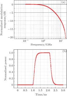
The dynamic responses of the sample, including modulation and pulse transient responses, can be obtained by the proposed model as well, which are illustrated in Fig. 5. Due to the lack of the probe station that can operate under very low temperature in our laboratory, the influence of the parasitic circuit could not be removed at present. Therefore experimental results of the modulation and pulse transient responses of the sample are not available here. However, the results calculated by the model, for example the ∼ 10 G 3-dB bandwidth and the ∼ 100 ps rising delay of pulse, are similar to those obtained by the other numerical methods in references, [14, 15] demonstrating the validity of this model for dynamic response simulation.
An equivalent circuit model of THz QCLs is proposed in this work based on the five-level rate equations. THz QCLs with RP structure are fabricated and characterized. The parameters in the model are derived from the MC simulation. Instead of complicated numerical methods, the proposed model is compatible with the circuit simulation and fast in calculation. The characteristics of THz QCLs at steady and dynamic states are simulated, including I– V, P– I, modulation bandwidth, and transient response. The validity of the model is verified by the experimental and numerical results, indicating that the proposed equivalent model is suitable and beneficial for system-level designs and optimizations.
| 1 |
|
| 2 |
|
| 3 |
|
| 4 |
|
| 5 |
|
| 6 |
|
| 7 |
|
| 8 |
|
| 9 |
|
| 10 |
|
| 11 |
|
| 12 |
|
| 13 |
|
| 14 |
|
| 15 |
|


