Zhao Tao, Zhong Ren-Bin†, Hu Min, Chen Xiao-Xing, Zhang Ping, Gong Sen, Liu Sheng-Gang. Tunable terahertz radiation from arbitrary profile dielectric grating coated with graphene excited by an electron beam. Chinese Physics B, 24(9): 094102
Permissions
Tunable terahertz radiation from arbitrary profile dielectric grating coated with graphene excited by an electron beam
Zhao Taoa),b), Zhong Ren-Bin†a),b), Hu Mina),b), Chen Xiao-Xinga),b), Zhang Pinga),b), Gong Sena),b), Liu Sheng-Ganga),b)
Terahertz Research Center, School of Physical Electronics, University of Electronic Science and Technology of China, Chengdu 610054, China
Cooperative Innovation Centre of Terahertz Science, Chengdu 610054, China
*Project supported by the National Basic Research Program of China (Grant No. 2014CB339801), the National Natural Science Foundation of China (Grant Nos. 61231005, 11305030, and 612111076), the Fundamental Research Funds for the Central Universities of China (Grant No. ZYGX2013J058), and the National High-tech Research and Development Project of China (Grant No. 2011AA010204).
Abstract
In this paper, the enhanced terahertz radiation transformed from surface plasmon polaritons, excited by a uniformly moving electron bunch, in a structure consisting of a monolayer graphene supported on a dielectric grating with arbitrary profile is investigated. The results show that the grating profile has significant influence on the dispersion curves and radiation characteristics including radiation frequency and intensity. The dependence of dispersion and radiation characteristics on the grating shape for both the symmetric and asymmetric gratings is studied in detail. Moreover, we find that, for an asymmetric grating with certain profile, there exist two different diffraction types, and one of the two types can provide higher radiation intensity comparing to the other one. These results will definitely facilitate the practical application in developing a room-temperature, tunable, coherent and miniature terahertz radiation source.
Graphene is a promising candidate to develop terahertz (THz) radiation sources by various methods, such as amplified stimulated emission, [1, 2] spontaneous radiation, [3] second-order nonlinear optical process, [4] cyclotron-like radiation process, [5] and diffraction radiation.[6, 7] References [6] and [7] both presented and explored the free-electron excited THz diffraction radiation source based on graphene surface plasmon polaritons (SPPs). Graphene has been proven to sustain SPPs with extreme high confinement and low Ohmic loss, [8, 9] and the features of SPPs can be tuned by adjusting external gate voltage or chemical doping.[10] These remarkable features are suitable for the development of tunable THz radiation sources based on graphene plasmonics. References [6] and [7] demonstrated that graphene SPPs can be effectively excited by an electron bunch uniformly moving along the surface of graphene, and can be transformed into enhanced THz radiation by the dielectric grating because the wave vector mismatch is removed. The radiation intensity reaches up to 103 W/cm2, which is hundreds times that without graphene due to the strong field enhancement of grapheme SPPs. This radiation mechanism could provide exciting opportunities to develop a room-temperature, tunable, coherent, and miniature THz radiation source.
In Refs. [6] and [7], for the structure of graphene situated on a dielectric grating, the grating with ideal rectangular shape is studied. Actually, limited by the manufacture process, the grating profile cannot keep rectangle with periodicity in macro- or nano-scale, and it is mostly with profile similar to sinusoid, triangle, or trapezoid.[11– 15] Therefore, investigating the influence of grating profile on the radiation characteristics will facilitate the practical application of this kind of THz radiation source. In this paper, the graphene SPPs enhanced THz radiation from graphene coated dielectric grating with arbitrary profile excited by an electron bunch is theoretically studied. The results show that the grating profile has significant influence on the dispersion curves and the radiation characteristics including radiation frequency and intensity.
This paper is organized as follows. In Section 2, based on the rigorous coupled-wave analysis, the general theoretical formulations are derived for the diffraction radiation from arbitrary shape grating covered with a monolayer graphene excited by an electron bunch. The theoretical and analytical results are given in Section 3. Section 4 gives the conclusions.
2. General theoretical formulations
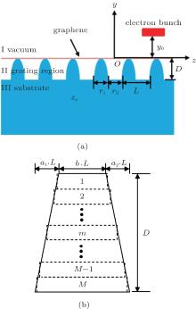
The model concerned here is an electron bunch moving above a monolayer graphene supported on a one-dimensional dielectric grating with arbitrary profile as shown in Fig. 1(a). The electron bunch is assumed to be a line charge with charge density ρ in the x direction, and it moves at a constant speed u0 along the z direction with trajectory distance y0 above the graphene. The grating has period L, and thickness D. Assume there are three space regions for the structure: the upper free space (vacuum) is region I, the grating area is region II, and the lower substrate is region III.
Fig. 1. (a) Schematic of graphene situated on a one-dimensional dielectric grating with arbitrary profile. (b) Multi-layer model of trapezoidal grating, the grating region is divided into M layers with equal thickness, and each layer approximates to be with rectangular profile.
The electromagnetic fields in region I consist of evanescent plane wave induced by the moving line charge along the z direction and its diffracted waves represented as an infinite sum of plane waves due to the periodicity of grating.[6, 7]
The incident fields can be obtained by solving the following inhomogeneous Helmholtz equation in the Cartesian coordinate:[16]
The time factor is assumed to be e− jω t and suppressed throughout this paper.
The current density of the moving electron beam Jz is expressed as
Submitting Eq. (2) into Eq. (1), and making use of the Fourier transformation, the z component of electric field can be obtained in the frequency domain[16]
where q is the line charge density of electron beam, ω is circular frequency, ε 0 is the dielectric constant of vacuum, c is the light velocity in vacuum, k0 = ω /c is the wave vector in vacuum, kz = ω /u0 is the wave vector of electron beam along the z direction, and kc is the wave vector of electron beam along the y direction,
Besides the fields induced by the electron beam, there also exist diffraction fields in region I. It can be expressed as
where kzn = kz + 2π n/L, n is the number of space harmonics of the diffraction fields, and it is an integer.
Hence, the total electromagnetic fields in region I can be written as
In region III, there only exist the diffracted waves with the same form as that in region I,
where ε s is the relative permittivity of dielectric substrate,
Other components of fields in regions I and III can be obtained by solving Maxwell equations together with Ez.
For region II, the grating is divided into a large number of sufficiently thin grating layers with rectangular profile, which can approximate the arbitrary profile grating to an arbitrary degree of accuracy. The electromagnetic fields in each grating layer can be conveniently solved by the coupled-wave approach.[17, 18] For the m-th grating layer with filling factor fm, which is defined as the ratio of the width of dielectrics (particularly the dielectric medium with relative permittivity ε s) in the m-th grating layer to grating period. The periodic permittivity can be expanded in a Fourier series, and its inverse is also expressed in a Fourier series for numerical stability and fast converge, [19, 20]
where
DM = D, dm is the thickness of the m-th grating layer, and Dm is the distance from the bottom of the m-th grating layer to the top of grating.
The tangential electric and magnetic fields in the m-th grating layer are expressed in a Fourier expression
The electromagnetic fields in the grating layer obey the Maxwell equations
Submitting Eq. (8) into Eq. (9), eliminating the y component of electric fields can obtain the following eigen equation:
where I is the unity matrix, Kz is a diagonal matrix with diagonal elements kzn/k0, and the n, p-th element of Cm is cm, n– p. Am is the matrix with its n, p-th element α m, n– p, and is the eigen matrix.
By solving Eq. (10), all the eigenvalues and eigenvectors can be obtained, so the tangential magnetic field in the m-th grating layer can be expressed as
where N is the total number of space harmonics, wm, n, i and qm, i are the elements of the eigenvector matrix Wm, and the square root of the eigenvalues of the matrix , respectively. The field coefficients and are determined by the boundary conditions.
The tangential electric field can be obtained by solving Eq. (9) with the tangential magnetic field
where vm, n, i is the element of the product matrix Vm = AmWmQm, and qm, i is the diagonal element of the diagonal matrix Qm.
At the boundaries between each region and each grating layer, the tangential electric and magnetic fields are continuous. Due to the existence of surface current on the graphene layer at the boundary between region I and the first grating layer, the boundary conditions are given by
where the conductivity of graphene σ g is described by Drude model. Here only the intraband conductivity is considered for the THz frequency regime, [21, 22]
j is the imaginary unit, T is temperature, kB is Boltzmann constant, τ is the relaxation time, and μ c is chemical potential.
In region II, at the boundary between the m − 1 and m grating layer (y = – Dm – 1)
At the boundary between the last grating layer and the substrate region (y = – DM),
By solving equations under the above boundary conditions, the field coefficients can be obtained. To avoid the numerical instability, the enhanced transmittance matrix approach proposed by Moharam is used[23]
where
ZI and ZIII are diagonal matrices with the diagonal elements and respectively, Xm is a diagonal matrix with the diagonal elements exp(− k0qm, idm).
The radiation power intensity in regions I and III can be calculated by
3. Theoretical and analytical results
Based on the above general formulations, the influence of grating profile on the dispersion curves and radiation characteristics can be theoretically and numerically investigated. For the ideal rectangular grating, its period is L = 1.5 μ m, grating height is D = 0.6 μ m, filling factor is 0.45, and the relative permittivity of dielectric substrate is ε s = 11.6.[7] Values of T = 300 K, τ = 1.2 ps, and μ c = 0.35 eV are used throughout this paper.[6, 7, 24] Without loss of generality, we take a typical trapezoidal grating as example. The multi-layers model of trapezoidal grating is shown in Fig. 1(b), the grating region is equally divided into M thin grating layers, each layer approximates to be with rectangular profile. M = 20 is adopted for the numerical calculation with enough accurate results. Keep the period of trapezoidal grating same as that of rectangular grating, the bottom edge of trapezoid grating is fixed at 0.45 times that the period. We define the ratio of upper edge of trapezoid to period as grating profile factor b (0 < b < 0.45). Obviously, the sharper is the trapezoidal profile, the smaller is the value of b. When the trapezoidal grating is asymmetric, its profile can be completely defined with another parameter (a1 or a2) shown in Fig. 1(b). We will study the influence of grating profile in symmetry and asymmetry cases separately.
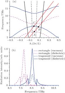
For the symmetric trapezoidal grating, its dispersion curves (the blue solid curves) are shown in Fig. 2(a), which are obtained by searching the poles caused by SPPs in the scattering matrix.[7, 25, 26] The dispersion curves of rectangular grating (the magenta dashed curves) are also depicted in Fig. 2(a) as a comparison. We can see that there both exist band gaps for the dispersion curves at the Brillouin zone center and boundaries for the two kinds of gratings because of multiple Bragg scattering arising from the periodicity of grating.[7, 27, 28] Due to the first dispersion band lying below the light line, SPPs of this band cannot be transformed into radiation, only the second and third bands of dispersion curves are given in this paper. For the rectangular grating structure, the frequencies at the Brillouin center of the dispersion bands are 7.82 THz and 8.84 THz, thus the band gap between them is 1.02 THz. For the trapezoidal grating structure, the dispersion bands apparently move up, comparing to those of rectangular structure. The corresponding frequencies increase by 9.7% and 17% to 8.58 THz and 10.34 THz, respectively, and the band gap is enlarged to 1.76 THz. To understand the physical mechanism of the huge upward shifting of the dispersion curves, a homogeneously effective dielectric layer with relative permittivity ε eff = ε sfeff + (1 − feff) is introduced to describe the grating region. For the rectangular structure, the effective filling factor feff is equal to 0.45, while for the trapezoidal grating feff is bounded by b and 0.45 (b < feff < 0.45). The sharper the trapezoidal profile is, the smaller the value of b is. When the rectangular profile of grating turns into trapezoidal shape, the effective permittivity ε eff decreases due to the decrease of effective filling factor feff, which leads to the upward shifting of dispersion curves.[29, 30]
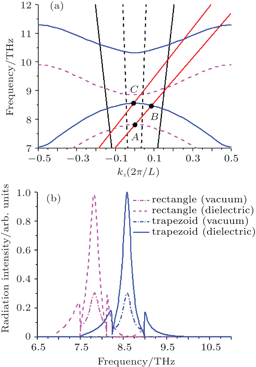
Fig. 2. (a) Dispersion curves for the structure of a monolayer graphene suited on the rectangular (the magenta dashed curves) and symmetrical trapezoidal (the blue solid curves) gratings, where b is equal to 0.3. (b) The radiation spectra of rectangular and symmetrical trapezoidal gratings, the peak frequencies correspond to the points A and C.
The radiation characteristics are also seriously affected by the change of grating profile. As shown in Fig. 2(a), the vacuum and substrate radiation areas are bounded by two vacuum light lines (two dashed lines symmetrical to the Brillouin center) and two dielectric light lines (two solid lines symmetrical to the Brillouin center), respectively. Obviously, there is an overlapped region bounded by two vacuum light lines for the two radiation areas, so the radiation wave with frequency locating in this region can radiate into both vacuum and substrate sides, while that in the non-overlapped radiation region can only radiate into the substrate side. Under the excitation of an electron beam with velocity 0.0391c, the beam line intersects with the dispersion curves of the rectangular grating at point A (the Brillouin center) in the overlapped radiation area, while this beam line will intersects with the dispersion curves at point B in the non-overlapped region when the grating profile changes to trapezoid, so the radiation of point B can only radiate into the substrate side. To obtain the intersection point at the Brillouin center for the trapezoidal grating, the electron beam velocity must be increased to 0.0429c, and the intersection point is C.
The radiation spectra of rectangular grating (the dashed curves) and symmetrical trapezoidal grating (the solid curves) excited by the electron bunch with velocities 0.0391c and 0.0429c are shown in Fig. 2(b). The results are in agreement with those in Fig. 2(a), the peak radiation frequency of rectangular grating is 7.82 THz corresponding to the point A, while that of trapezoidal grating largely blue shifts to 8.58 THz, corresponding to the point C. The radiation intensity in substrate is much higher than that in vacuum for both two kinds of gratings, [7] and the radiation intensity from trapezoidal grating is little stronger than that from rectangular grating both in the vacuum and substrate sides. This is caused by a stronger interaction between the electron beam and graphene SPPs at higher frequency, which leads to the higher intensity of excited SPPs on the graphene sheet, and in turn higher transformed radiation intensity.
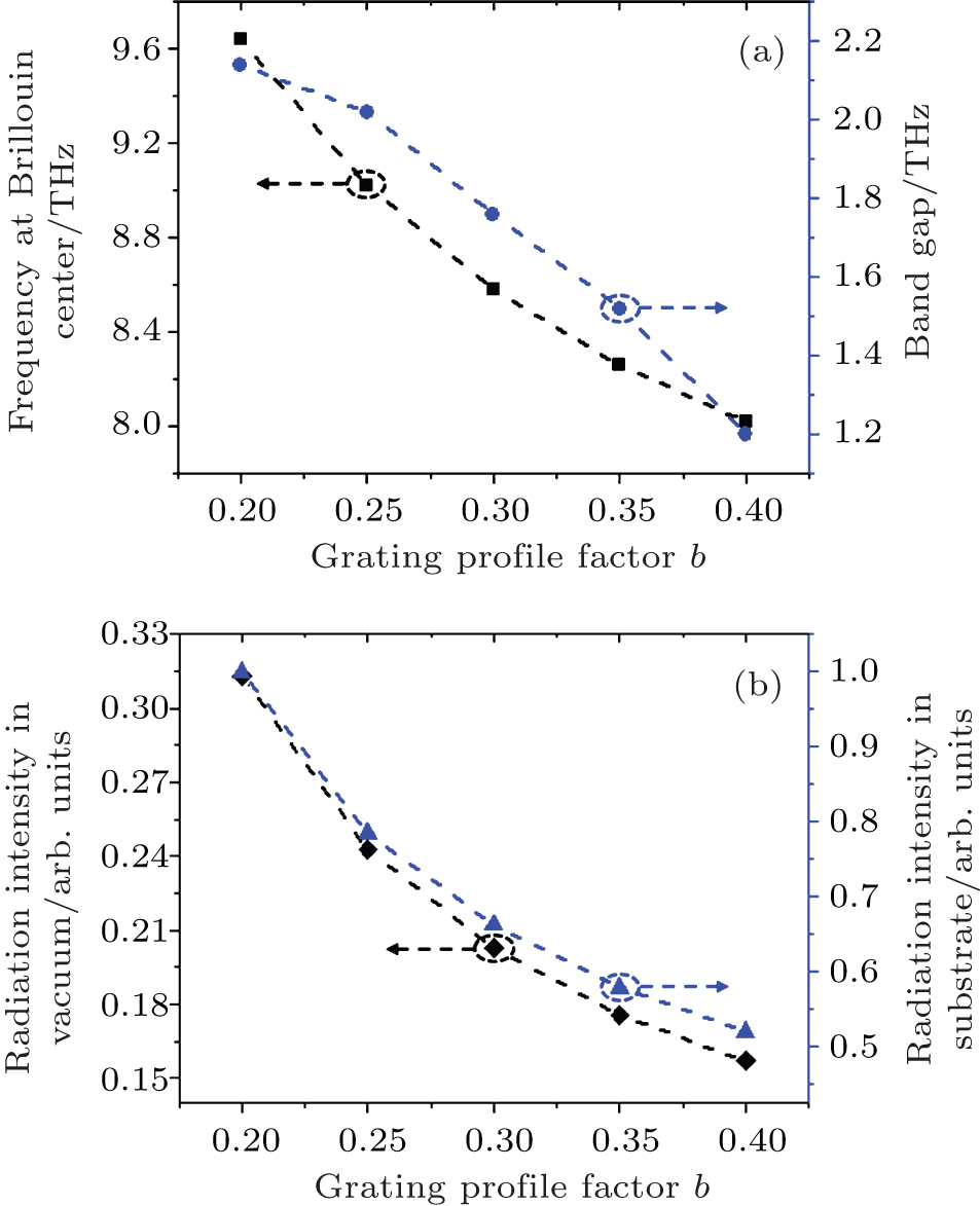
The dependence of dispersion and radiation characteristics on the grating profile factor b for the symmetrical trapezoidal grating is studied in detail. Figure 3(a) shows that the dispersion characteristics including the frequency at the Brillouin center of the second dispersion band and the band gap varies with b. It can be seen that with the decrease of b (the more change of grating profile), both the frequency and band gap increase. When b decreases 30%, the frequency increases 23%, and the band gap even increases 110%. It is because the permittivity of effective medium ε eff decreases with the decrease of b, which leads to the increase of frequency and band gap. Figure 3(b) shows the intensity of radiation waves toward the vacuum and substrate sides increases with the decrease of b. When b decreases 30%, the radiation intensity both in the vacuum and substrate sides is doubled. The enhancement comes from a stronger interaction between the electron beam and graphene SPPs at higher frequency, which leads to the higher intensity of excited SPPs on the graphene sheet, and in turn higher transformed radiation intensity.
Fig. 3. (a) Frequency at the Brillouin center of the second dispersion band and band gap versus the grating profile factor b for the symmetrical trapezoidal grating. (b) Radiation intensity with frequency at the Brillouin center of the second dispersion band in vacuum and substrate sides versus the grating profile factor b, other parameters are the same as that used in Fig. 2.
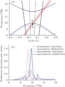
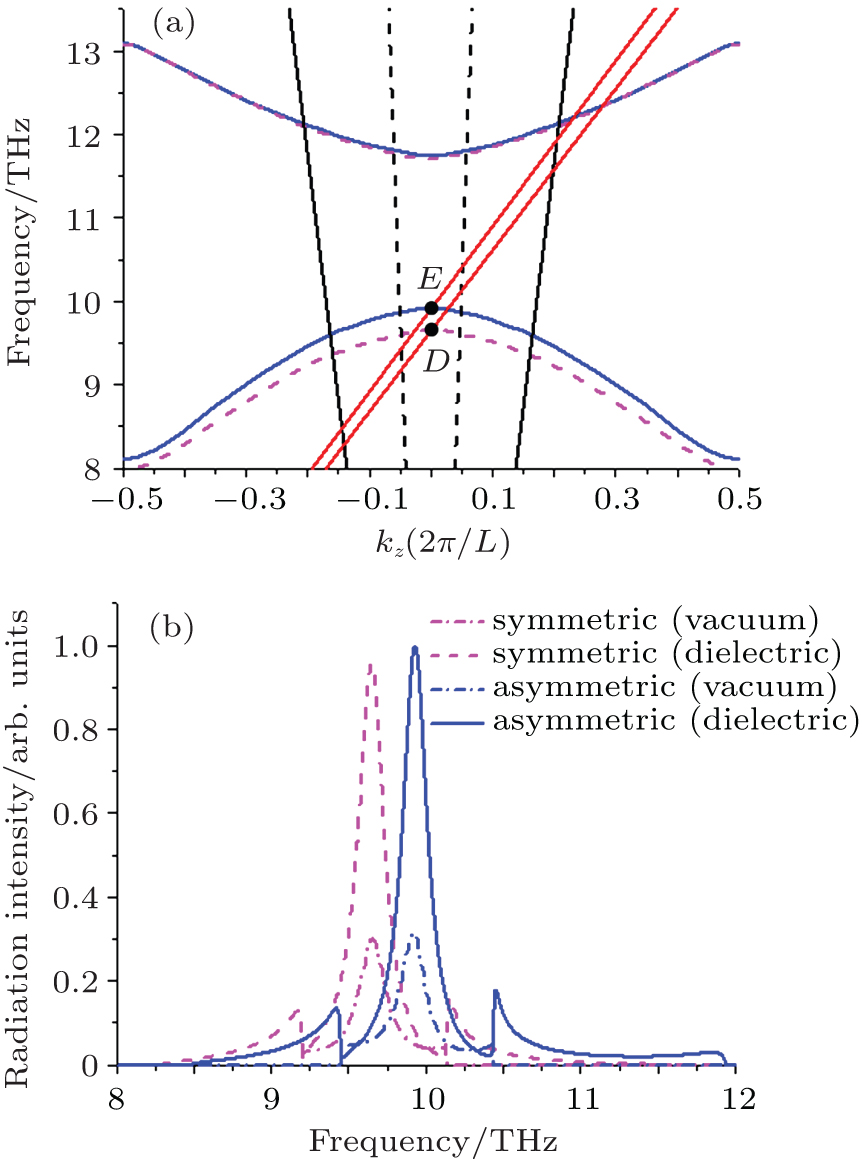
Now we investigate the influence of asymmetry of grating on dispersion and radiation characteristics. The profile parameter a1 (or a2) can be regarded as the asymmetry factor due to the asymmetry degree of trapezoidal grating increases with the decrease of a1 (or a2). Figure 4(a) shows the dispersion curves for the symmetrical (the magenta dashed curves) and asymmetrical (the blue solid curves) trapezoidal grating. We can see that the asymmetry also leads to the change of dispersion curves. Comparing to the symmetrical grating, the second dispersion band of asymmetrical grating apparently moves up, the third dispersion band slightly, and the band gap is decreased. The intersection point between beam line and dispersion curves at the Brillouin center changes from D to E, and the beam velocity is increased from 0.0483c to 0.0505c. Figure 4(b) shows their radiation spectra, the peak radiation frequency of symmetrical grating is 9.65 THz corresponding to the point D, while that of asymmetrical grating blue shifts to 10.1 THz corresponding to the point E. The radiation intensity from asymmetrical grating is little higher than that from symmetrical grating both in the vacuum and substrate sides. The reason is the same as that given in the comparison of radiation intensity of rectangular and trapezoidal gratings.
Fig. 4. (a) Dispersion curves for the symmetrical (the magenta dashed curves) and asymmetrical (the blue solid curves) trapezoidal grating, where b is equal to 0.2, a1 is equal to 0.1, and other parameters are the same as that used in Fig. 2. (b) Radiation spectra of the symmetrical (the dashed curves) and asymmetrical (the solid curves) trapezoidal gratings.
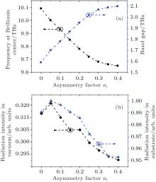
Figure 5(a) shows that the dispersion characteristics including the frequency at the Brillouin center of the second dispersion band and the band gap varies with the profile parameter a1. With the increasing asymmetry (the decrease of a1), the frequency increases compared to that of symmetrical grating, while the band gap decreases, which is caused by the fact that the second dispersion band moves up more with the decrease of a1 and the third dispersion band changes little. Figure 5(b) shows the intensity of radiation waves toward the vacuum and substrate sides increases firstly with the decrease of a1, reaches a peak value at a1 = 0.05, then decreases.
Fig. 5. (a) Frequency at the Brillouin center of the second dispersion band and band gap versus the asymmetry factor a1. (b) Radiation intensity with frequency at the Brillouin center of the second dispersion band in vacuum and substrate sides versus the asymmetry factor a1. Other parameters are the same as that used in Fig. 4.
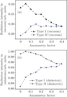
For an asymmetrical trapezoidal grating with a fixed profile, there exist two different diffraction types. Assume Type I is the one with a1 < a2, then Type II is another one with a1 > a2. The dispersion curves are the same for both types due to the rotational symmetry (Type I is equivalent to Type II when it rotates 180 degree around the y axis), while the radiation intensity are quite different because of the breaking of rotational symmetry by the directivity of excited propagating SPPs. Figure 6 shows the intensity of radiation wave with frequency at the Brillouin center of the second dispersion band in vacuum and substrate sides varies with the asymmetry factor for the two types. The radiation intensity of Type I is higher than that of Type II both in vacuum and dielectric sides, and the difference of radiation intensity between them increases with the increase of asymmetry. These results indicate that Type I is prior to Type II in transforming SPPs into radiation wave, and hence in the practical application, Type I is preferred.
Fig. 6. Intensity of radiation wave with frequency at the Brillouin center of the second dispersion band in vacuum (a) and substrate (b) sides versus the asymmetry factor for the two diffraction types, the asymmetry factor is a1 for Type I, and it is a2 for Type II.
4. Conclusions
Theoretical and numerical study was carried out for the enhanced THz radiation transformed from surface plasmon polaritons excited by an electron bunch in a structure consisting of a monolayer graphene situated on a dielectric grating with arbitrary profile. The results show that the grating profile has significant influence on the dispersion curves and radiation characteristics. When the grating profile changes from rectangle to trapezoid, the dispersion curves move up, the band gap is enlarged, and the radiation frequency blue shifts with higher exciting beam velocity. The more the grating shape changes, the greater the variations of these dispersion and radiation characteristics are. Furthermore, the asymmetry of grating profile can affect the dispersion curves and radiation characteristics as well. The radiation frequency increases with the increase of asymmetry, while the band gap decreases. The variation of radiation intensity is more complicated. It increases firstly to a peak value, then decreases. In addition, for an asymmetric grating with certain profile, there are two different diffraction types, and Type I is prior to Type II in transforming SPPs into radiation wave. These results can facilitate the practical application in the development of a room-temperature, tunable, coherent, and miniature THz radiation source.
Boubanga-TombetS, ChanS, WatanabeT, SatouA, RyzhiiV and OtsujiT2012Phys. Rev. B85035443DOI:10.1103/PhysRevB.85.035443[Cited within:1]
2
WatanabeT, FukushimaT, YabeY, TombetS A B, SatouA, DubinovA A, AleshkinY V, MitinV, RyzhiiV and OtsujiT2013New J. Phys. 15075003DOI:10.1088/1367-2630/15/7/075003[Cited within:1]
... IntroductionGraphene is a promising candidate to develop terahertz (THz) radiation sources by various methods, such as amplified stimulated emission,[1,2] spontaneous radiation,[3] second-order nonlinear optical process,[4] cyclotron-like radiation process,[5] and diffraction radiation ...
1
2013
0.0
0.0
... IntroductionGraphene is a promising candidate to develop terahertz (THz) radiation sources by various methods, such as amplified stimulated emission,[1,2] spontaneous radiation,[3] second-order nonlinear optical process,[4] cyclotron-like radiation process,[5] and diffraction radiation ...
1
2012
0.0
0.0
... IntroductionGraphene is a promising candidate to develop terahertz (THz) radiation sources by various methods, such as amplified stimulated emission,[1,2] spontaneous radiation,[3] second-order nonlinear optical process,[4] cyclotron-like radiation process,[5] and diffraction radiation ...
1
2009
0.0
0.0
... IntroductionGraphene is a promising candidate to develop terahertz (THz) radiation sources by various methods, such as amplified stimulated emission,[1,2] spontaneous radiation,[3] second-order nonlinear optical process,[4] cyclotron-like radiation process,[5] and diffraction radiation ...
1
2013
0.0
0.0
... IntroductionGraphene is a promising candidate to develop terahertz (THz) radiation sources by various methods, such as amplified stimulated emission,[1,2] spontaneous radiation,[3] second-order nonlinear optical process,[4] cyclotron-like radiation process,[5] and diffraction radiation ...
6
2014
0.0
0.0
... [6,7] References#cod#x00A0 ...
... [6] and [7] both presented and explored the free-electron excited THz diffraction radiation source based on graphene surface plasmon polaritons (SPPs) ...
... [6] and [7] demonstrated that graphene SPPs can be effectively excited by an electron bunch uniformly moving along the surface of graphene, and can be transformed into enhanced THz radiation by the dielectric grating because the wave vector mismatch is removed ...
... [6] and [7], for the structure of graphene situated on a dielectric grating, the grating with ideal rectangular shape is studied ...
... [6,7] ...
... [6,7,24] Without loss of generality, we take a typical trapezoidal grating as example ...
10
2014
0.0
0.0
... [6,7] References#cod#x00A0 ...
... [6] and [7] both presented and explored the free-electron excited THz diffraction radiation source based on graphene surface plasmon polaritons (SPPs) ...
... [6] and [7] demonstrated that graphene SPPs can be effectively excited by an electron bunch uniformly moving along the surface of graphene, and can be transformed into enhanced THz radiation by the dielectric grating because the wave vector mismatch is removed ...
... [6] and [7], for the structure of graphene situated on a dielectric grating, the grating with ideal rectangular shape is studied ...
... [6,7] ...
... [7] Values of T #cod#x003D ...
... [6,7,24] Without loss of generality, we take a typical trapezoidal grating as example ...
... [7,25,26] The dispersion curves of rectangular grating (the magenta dashed curves) are also depicted in Fig ...
... [7,27,28] Due to the first dispersion band lying below the light line, SPPs of this band cannot be transformed into radiation, only the second and third bands of dispersion curves are given in this paper ...
... The radiation intensity in substrate is much higher than that in vacuum for both two kinds of gratings,[7] and the radiation intensity from trapezoidal grating is little stronger than that from rectangular grating both in the vacuum and substrate sides ...
1
2003
0.0
0.0
... Graphene has been proven to sustain SPPs with extreme high confinement and low Ohmic loss,[8,9] and the features of SPPs can be tuned by adjusting external gate voltage or chemical doping ...
1
2011
0.0
0.0
... Graphene has been proven to sustain SPPs with extreme high confinement and low Ohmic loss,[8,9] and the features of SPPs can be tuned by adjusting external gate voltage or chemical doping ...
1
2011
0.0
0.0
... [10] These remarkable features are suitable for the development of tunable THz radiation sources based on graphene plasmonics ...
1
1988
0.0
0.0
... [11#cod#x2013 ...
1
2000
0.0
0.0
1
2005
0.0
0.0
1
2007
0.0
0.0
1
2013
0.0
0.0
... 15] Therefore, investigating the influence of grating profile on the radiation characteristics will facilitate the practical application of this kind of THz radiation source ...
2
2012
0.0
0.0
... The incident fields can be obtained by solving the following inhomogeneous Helmholtz equation in the Cartesian coordinate:[16] ...
... (1), and making use of the Fourier transformation, the z component of electric field can be obtained in the frequency domain[16] ...
1
1981
0.0
0.0
... [17,18] For the m-th grating layer with filling factor fm, which is defined as the ratio of the width of dielectrics (particularly the dielectric medium with relative permittivity #cod#x03B5 ...
1
1982
0.0
0.0
... [17,18] For the m-th grating layer with filling factor fm, which is defined as the ratio of the width of dielectrics (particularly the dielectric medium with relative permittivity #cod#x03B5 ...
1
1993
0.0
0.0
... The periodic permittivity can be expanded in a Fourier series, and its inverse is also expressed in a Fourier series for numerical stability and fast converge,[19,20] ...
1
1996
0.0
0.0
... The periodic permittivity can be expanded in a Fourier series, and its inverse is also expressed in a Fourier series for numerical stability and fast converge,[19,20] ...
1
2008
0.0
0.0
... Here only the intraband conductivity is considered for the THz frequency regime,[21,22] ...
1
2012
0.0
0.0
... Here only the intraband conductivity is considered for the THz frequency regime,[21,22] ...
1
1995
0.0
0.0
... To avoid the numerical instability, the enhanced transmittance matrix approach proposed by Moharam is used[23] ...
1
2008
0.0
0.0
... [6,7,24] Without loss of generality, we take a typical trapezoidal grating as example ...
1
1996
0.0
0.0
... [7,25,26] The dispersion curves of rectangular grating (the magenta dashed curves) are also depicted in Fig ...
1
1999
0.0
0.0
... [7,25,26] The dispersion curves of rectangular grating (the magenta dashed curves) are also depicted in Fig ...
1
2012
0.0
0.0
... [7,27,28] Due to the first dispersion band lying below the light line, SPPs of this band cannot be transformed into radiation, only the second and third bands of dispersion curves are given in this paper ...
1
2012
0.0
0.0
... [7,27,28] Due to the first dispersion band lying below the light line, SPPs of this band cannot be transformed into radiation, only the second and third bands of dispersion curves are given in this paper ...
1
2013
0.0
0.0
... [29,30] ...
1
2015
0.0
0.0
... [29,30] ...
Tunable terahertz radiation from arbitrary profile dielectric grating coated with graphene excited by an electron beam
[Zhao Taoa),b), Zhong Ren-Bin†a),b), Hu Mina),b), Chen Xiao-Xinga),b), Zhang Pinga),b), Gong Sena),b), Liu Sheng-Ganga),b)]


 , Hu Min