Liu Si-Yuan, Zheng Bu-Sheng, Li Hai-Ming, Liu Xiao-Chun, Liu Shao-Bin†. Double transmission peaks electromagnetically induced transparency induced by simultaneously exciting the electric and magnetic resonance in one unit cell. Chinese Physics B, 24(8): 084204
Permissions
Double transmission peaks electromagnetically induced transparency induced by simultaneously exciting the electric and magnetic resonance in one unit cell
Liu Si-Yuana), Zheng Bu-Shenga), Li Hai-Minga), Liu Xiao-Chunb), Liu Shao-Bin†a)
Key Laboratory of Radar Imaging and Microwave Photonics, Ministry of Education, College of Electronic and Information Engineering, Nanjing University of Aeronautics and Astronautics, Nanjing 210016, China
The Aeronautical Science Key Laboratory for High Performance Electromagnetic Windows, Jinan 250023, China
*Project supported by the Chinese Specialized Research Fund for the Doctoral Program of Higher Education, China (Grant No. 20123218110017), the National Natural Science Foundation of China (Grant Nos. 61307052 and 61471368), the Foundation of Aeronautical Science, China (Grant No. 20121852030), and the Fundamental Research Funds for the Central Universities (Grant No. kfjj20150407).
Abstract
In this paper, we investigate a metamaterial formed by a planar array of a metallic L-shaped structure and a cut wire (CW), which behaves as an analogue of the electromagnetically induced transparency (EIT). The double transmission peaks are formed by the destructive interference of two bright-modes and a quasi-dark mode. The two bright-modes are respectively excited by the L-shaped structure and CW. The unit structure itself performs a quasi-dark mode. The group refractive indexes are over 20 in the first transmission peak, and 117 in the second transmission peak, thus offering potential applications in slow light devices. Finally, all the above characteristics are achieved in just one simple unit cell.
PACS:
42.50.Dv; 03.67.Mn
Keyword:
electromagnetically induced transparency; double transmission peaks
The analogue of the electromagnetically induced transparency (EIT) has attracted a lot of attention during the past decade, and this phenomenon is induced by destructive quantum interference between two excitation resonances, which is useful in slow or stopped light, [1– 3] sensing, [4, 5] surface-enhanced Raman scattering (SERS), [6] optical modulation and switching, [7– 9] and nanoscale plasmon rulers[10] applications. Many researchers have demonstrated theoretically and experimentally the analogue of EIT phenomenon based on optical dipole antennas, [11] trapped-mode patterns, [12] split-ring resonators, [13– 15] and array of metallic nanoparticles.[16] In these applications, the phenomena of slow or stopped light are surely the most stunning EIT effects. The latter is a key component in optical (quantum) information processing, e.g., in deterministic single photon sources, quantum networks, or quantum repeaters.[17] Thus, the giant group refractive indexes have shown great promise in developing novel slow light devices. Many EIT structures[1, 4, 5] have been realized based on planar and three-dimensional (3D) metamaterials.[18, 19] Among them, the realization of the EIT phenomenon in a single-layered metamaterial is highly advantageous because it can be easily fabricated.
The classical unit cell of EIT metamaterial includes cut wires (CWs), fishnets, split-ring resonators (SRRs), [20] etc. Most of the earlier efforts focus on demonstrating analogue EIT by using the electric resonators and the magnetic resonators with different structures. Among them, the electric resonance is excited by the incident electric field, [21– 23] and the magnetic resonance is excited by the near-field coupling of the radiative mode.[24] Besides, many researches focused on incident electric fields near-field coupling to the magnetic or electric resonance to generate EIT.[25, 26] However, there are few reports concerning the EIT with electric and magnetic resonance simultaneously excited by the incident electromagnetic wave.
Here, we present a design with a single-layered EIT metamaterial that can generate double transmission peaks. The electric and magnetic resonances in the unit cell of EIT metamaterial are simultaneously excited by the incident electric and magnetic field, respectively. The group refractive indexes are over 117 in the second transmission peak, which may have potential applications in slow light devices.
2. Structure design
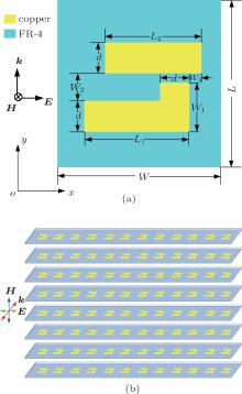
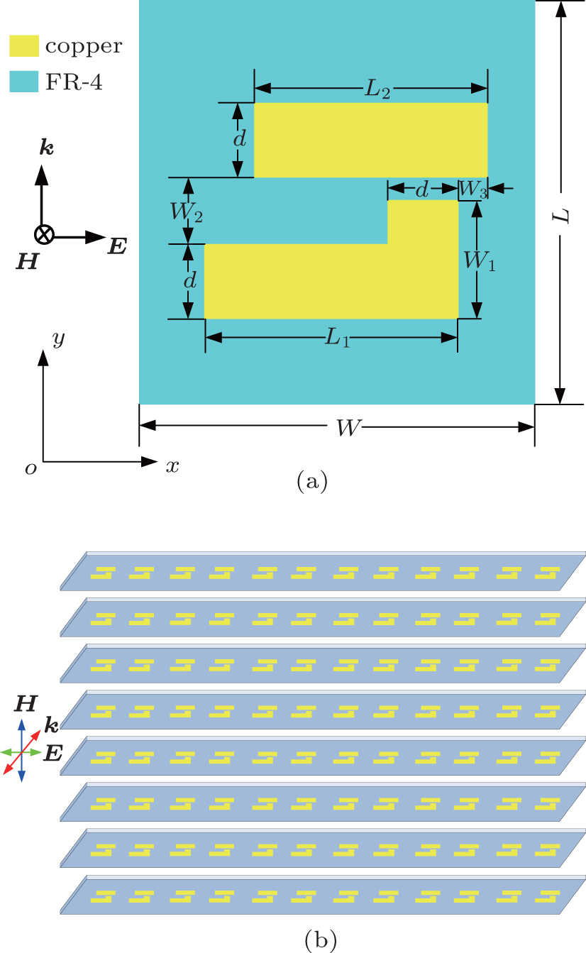
As is well known, the EIT phenomenon is mostly composed of bright– bright mode or bright– dark mode. In order to obtain a simple structure, we design the unit cell of the EIT metamaterial consisting of a CW and an L-shaped structure in this paper as shown in Fig. 1(a). The construction of the metamaterial array proposed here in this work is shown in Fig. 1(b).
Fig. 1. Schematics of (a) EIT unit cell and (b) our proposed metamaterial array.
The incident electromagnetic wave with the wavenumber k, electric field E, and magnetic field H impinges along the normal direction to the metamaterial array surface. When the direction of electric field polarization is along the x axis, the CW and L-shaped structure can be respectively excited by the incident electromagnetic wave. The EIT phenomenon (double transmission peaks) in the present study is composed of bright– dark– bright mode. Two electric resonances (two bright modes) in the CW and L-shaped structure can be produced in the direction parallel to the incident electric field. When the direction of magnetic field polarization is along the z axis, the CW and the L-shaped structure joined together can be considered as an analogue of split-ring resonator, [27] which leads to magnetic resonance and can be chosen as a quasi-dark mode.
With the incident electromagnetic wave excitation, two EIT-like sharp transmission peaks can be observed. Due to destructive interference effects between the first bright mode (the L-shaped structure) and quasi-dark mode (the SRR-like), and between the second bright mode (the CW structure) and quasi-dark mode, the EIT structure takes on double transmission peaks with different group refractive indexes. Underlying physics can be explained by induced surface currents.
3. Simulated and experimental results
As shown in Fig. 1, the geometrical dimensions of this metamaterial unit cell are as follows: W = 27.4 mm, L = 35.2 mm, d = 3.4 mm, L1 = 9.2 mm, W1 = 4.6 mm, L2 = 8.4 mm W2 = 1.8 mm, and W3 = 1.4 mm. Figure 1(b) shows the fabricated metamaterial array, which has 20 unit cells along the x axis and 30 unit cells along the z axis. The overall size of the whole metamaterial array is 576 mm× 548 mm. The L-shaped structure and CW are patterned on FR-4 board with a thickness of 1.8 mm (permittivity ε r = 4.30).
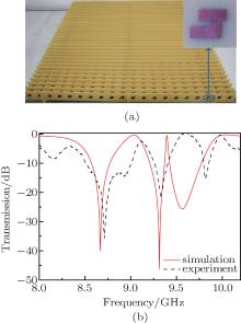
To clarify the underlying mechanism of the EIT effect, We use software CST Microwave Studio and Matlab to conduct our simulation and fabricate the sample of our metamaterial array for the experiment as illustrated in Fig. 2(a). The sample is measured with a pair of X-band broadband horn antennas and a vector network analyzer (N5230C) in a microwave anechoic chamber. Figure 2(b) shows the measured (black dash line) and simulated (red solid line) transmittance spectra of our metamaterial array with the incident electromagnetic field excitation. Figure 2(a) shows that the simulated result is basically in agreement with the measured result. However, the experimental result shows a slight frequency drift, especially in the high frequency band, which is due to the deformation from accidental error in experiment and manufacture craft of the FR-4 substrate.
Fig. 2. (a) Photograph of fabricated EIT structure, with the inset showing the amplified part of the unit cell. (b) Measured (black dashed line) and simulated (red solid line) transmission spectra as a function of frequency.
From Fig. 2(b), we can observe two transmission peaks at the frequencies of 9.06 GHz and 9.40 GHz and three transmission dips at frequencies of 8.65 GHz, 9.30 GHz, and 9.59 GHz. On the left side of the first peak and right side of the second peak (frequency < 8.25 GHz and 10.00 GHz < frequency < 10.30 GHz), the transmission curve is smooth without any other clutter resonance. The two transmission peaks are caused by the destructive interference between two bright modes and a quasi-dark mode. Under the condition of single electric or magnetic resonance, corresponding Q-values of three resonators are as follows: Q1 = 65 (L-shaped structure), Q2 = 94 (CW), and Q3 = 335 (SRR-like structure). The quality factor (Q-value) can be calculated from the center frequency divided by the half maximum bandwidth. The mutual coupling of three resonators (Q1 < Q2 < Q3) forms the double transmission peaks. The difference between the Q3 and Q1 is larger than that between the Q3 and Q2, which is the reason why the Q-value of right transmission peak (Q = 226) is larger than that of the left transmission peak (Q = 26).
4. Surface current distributions and group index
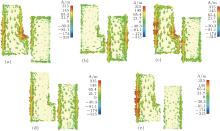
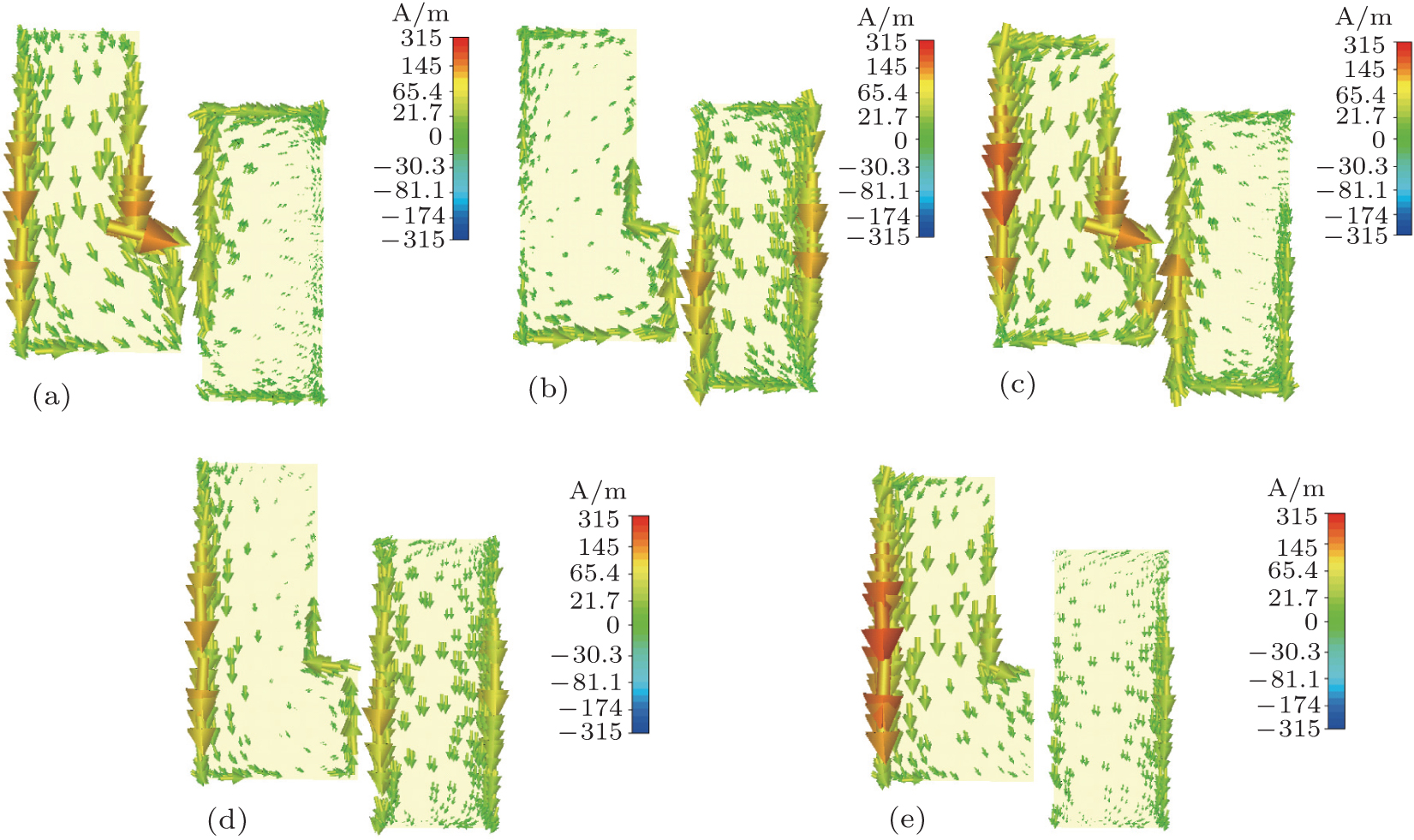
In order to gain an insight into the underlying physics of our proposed EIT structure, the surface current distributions at various frequencies are shown in Fig. 3. We can find that the surface current distributions along L-shaped structure are obviously larger than along cut wire at three different transmission dips (8.65 GHz, 9.30 GHz, and 9.59 GHz) in Figs. 3(a), 3(c), and 3(e). However, the Q-value of electronic resonance of the L-shaped structure is lower than that of the cut wire, which causes no uniform current distributions along the L-shaped structure nor the cut wire. At the transmission peaks (9.06 GHz and 9.40 GHz) in Figs. 3(b) and 3(d), the L-shaped structure and the cut wire both behave as an SRR, the surface current along it is weak, which is consistent with the scenario at high level transmission peaks in Fig. 2(a).
Fig. 3. Simulated surface current distributions for L-shaped structure and cut wire at frequencies (a) 8.65 GHz, (b) 9.06 GHz, (c) 9.30 GHz, (d) 9.40 GHz, and (e) 9.59 GHz.
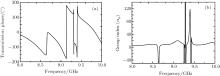
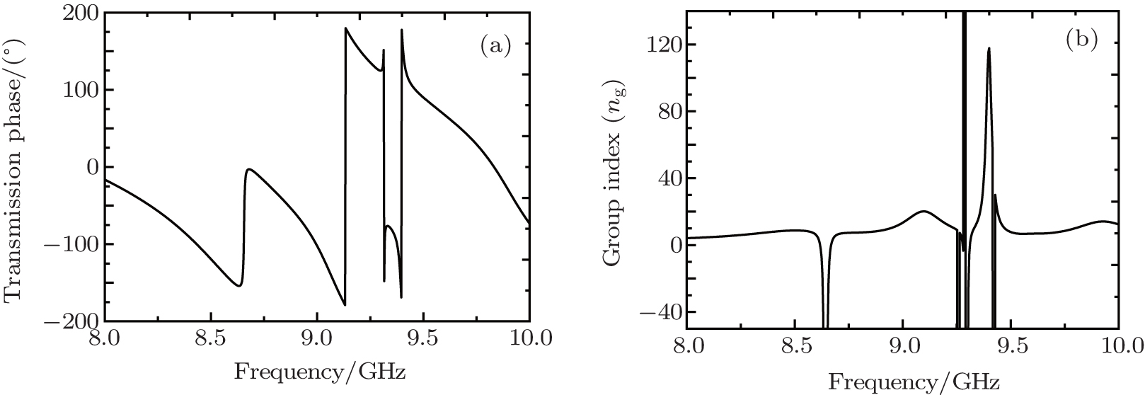
The refractive index of a large group is clearly useful for the slow light. The group refractive index can be defined by ng = n + ω dω /dn, where n refers to the effective refractive index and it can be extracted from the numerical simulations of the transmission and reflection coefficient by using a well-established retrieval algorithm. From two transparency windows, we can observe strong dispersion (see Fig. 4(a)). The group refractive index at first transmission peak is over 20 and the group refractive index at two transmission peaks is over 117, which can be obtained from Fig. 4(b). The EIT structure with such a large group refractive index may have potential applications in slow light devices.
Fig. 4. Simulated phase (a) and group refractive index (b) as a function of frequency.
5. Effective parameter of the unit structure
It is obvious that the FR-4 board, the SRR-like structure, and the size of unit cell will affect the transmission spectra. These parameters include the thickness of the substrate, d, L1, L2, W1, and W2.
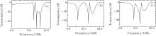
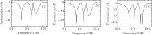
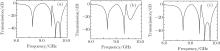
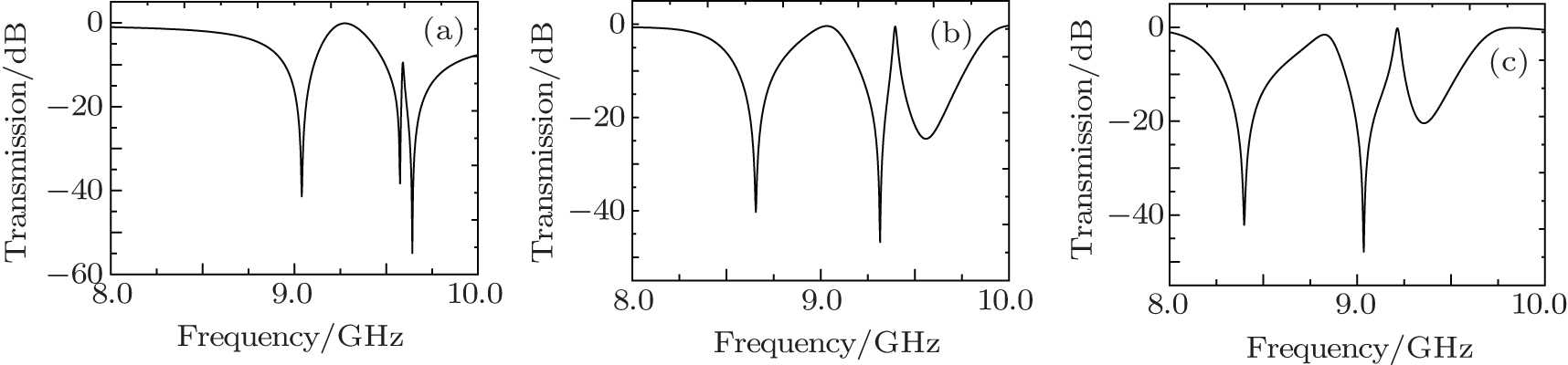
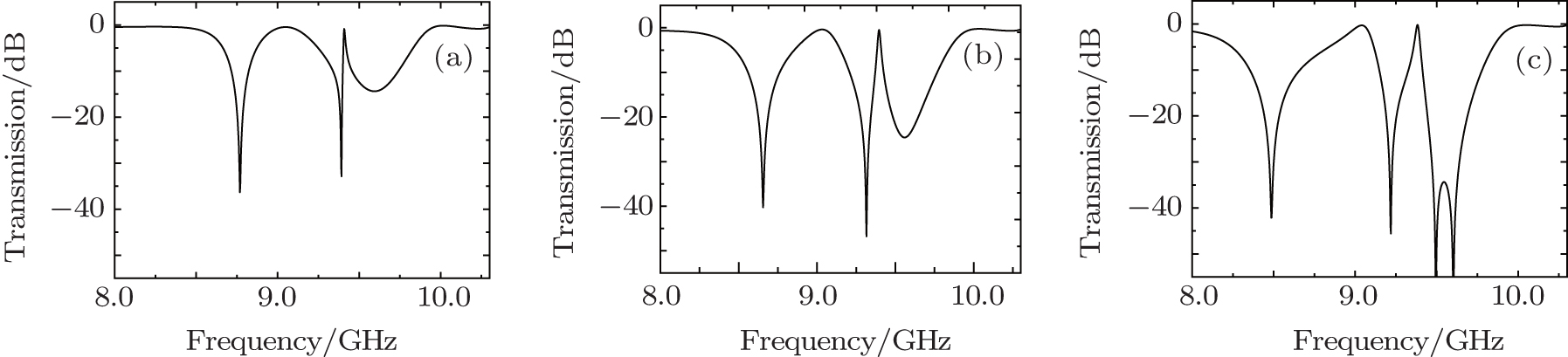
Figure 5 shows transmission spectra with frequency for the three different values of substrate thickness. The values of the substrate thickness are 1.6 mm, 1.8 mm, and 2.0 mm, respectively. From Fig. 5, it can be observed that the values of substrate thickness have little influence on the shape of double peak. With the increasing of the substrate thickness, the frequency of peak and dip shift toward the low-frequency, and the second peak of Q-value obviously decreases. There are two potential reasons for this phenomenon: one is that the dielectric loss increases as the substrate thickness increases, which leads to the decrease of Q-value; the other is that the equivalent conductivity and permeability of metamaterial increase as the substrate thickness increases, which leads to the decreases of frequency of peaks and dips.
Fig. 5. Transmission spectra when the thickness values of the substrate are (a) 1.6 mm, (b) 1.8 mm, (c) 2.0 mm.
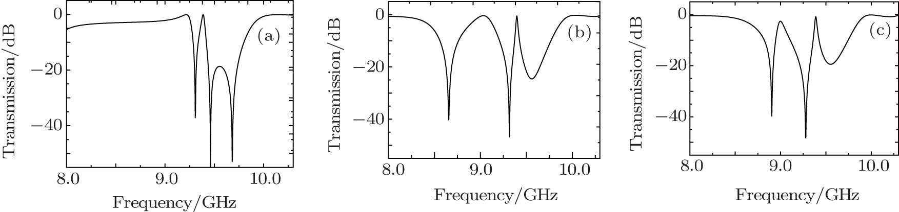
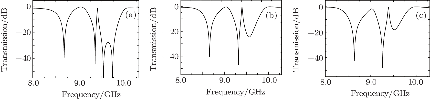
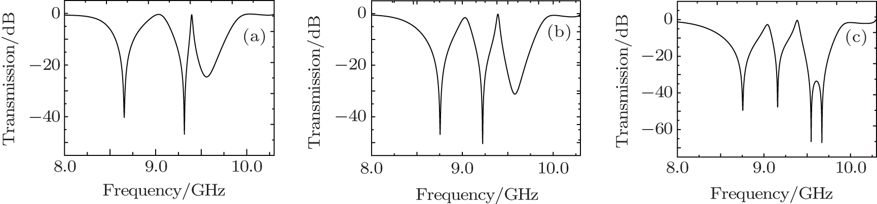
We can clearly see that there are two transmission peaks and the frequencies of the two transmission peaks are almost unchanged as the d, L1, L2, W1, and W2 change within a certain range as shown in Figs. 6– 10, which show that our EIT-like metamaterial has strong stability. The strong stability may have potential applications in slow light devises.
Fig. 10. Transmission spectra when the values of W2 are (a) 1.6 mm, (b) 1.8 mm, (c) 2.0 mm.
6. Conclusions
In this work, we proposed a new type of EIT-like structure having a double transmission peak with simultaneously excited electric and magnetic resonance. Two EIT-like narrow transmission windows with transmission peaks located between three dips is observed in simulated transmission spectra. Moreover, each phase changes steeply between the dips constituting a double transmission peak, and the group refractive index of the second transmission peak exceeds 117. The large group refractive index may have potential applications in slow light devices. In addition, double transmission peak EIT-like metamaterial with simultaneously exciting electric and magnetic resonance can enrich metamaterial analogy electromagnetically induced transparency.
WuC, KhanikaevA B, AdatoR, ArjuN, YanikA A, AltugH and ShvetsG2012Nat. Mater. 1169DOI:10.1038/nmat3161[Cited within:1]
2
2009
0.0
0.0
... IntroductionThe analogue of the electromagnetically induced transparency (EIT) has attracted a lot of attention during the past decade, and this phenomenon is induced by destructive quantum interference between two excitation resonances, which is useful in slow or stopped light,[1#cod#x2013 ...
... Many EIT structures[1,4,5] have been realized based on planar and three-dimensional (3D) metamaterials ...
... 9] and nanoscale plasmon rulers[10] applications ...
1
2011
0.0
0.0
... 9] and nanoscale plasmon rulers[10] applications ...
1
2008
0.0
0.0
... Many researchers have demonstrated theoretically and experimentally the analogue of EIT phenomenon based on optical dipole antennas,[11] trapped-mode patterns,[12] split-ring resonators,[13#cod#x2013 ...
1
2008
0.0
0.0
... Many researchers have demonstrated theoretically and experimentally the analogue of EIT phenomenon based on optical dipole antennas,[11] trapped-mode patterns,[12] split-ring resonators,[13#cod#x2013 ...
1
2009
0.0
0.0
... Many researchers have demonstrated theoretically and experimentally the analogue of EIT phenomenon based on optical dipole antennas,[11] trapped-mode patterns,[12] split-ring resonators,[13#cod#x2013 ...
1
2013
0.0
0.0
1
2012
0.0
0.0
... 15] and array of metallic nanoparticles ...
1
2009
0.0
0.0
... [16] In these applications, the phenomena of slow or stopped light are surely the most stunning EIT effects ...
1
2013
0.0
0.0
... [17] Thus, the giant group refractive indexes have shown great promise in developing novel slow light devices ...
1
2012
0.0
0.0
... [18,19] Among them, the realization of the EIT phenomenon in a single-layered metamaterial is highly advantageous because it can be easily fabricated ...
1
2010
0.0
0.0
... [18,19] Among them, the realization of the EIT phenomenon in a single-layered metamaterial is highly advantageous because it can be easily fabricated ...
1
2014
0.0
0.0
... The classical unit cell of EIT metamaterial includes cut wires (CWs), fishnets, split-ring resonators (SRRs),[20] etc ...
1
2009
0.0
0.0
... Among them, the electric resonance is excited by the incident electric field,[21#cod#x2013 ...
1
2014
0.0
0.0
1
2014
0.0
0.0
... 23] and the magnetic resonance is excited by the near-field coupling of the radiative mode ...
1
2012
0.0
0.0
... [24] Besides, many researches focused on incident electric fields near-field coupling to the magnetic or electric resonance to generate EIT ...
1
2011
0.0
0.0
... [25,26] However, there are few reports concerning the EIT with electric and magnetic resonance simultaneously excited by the incident electromagnetic wave ...
1
2012
0.0
0.0
... [25,26] However, there are few reports concerning the EIT with electric and magnetic resonance simultaneously excited by the incident electromagnetic wave ...
1
2012
0.0
0.0
... When the direction of magnetic field polarization is along the z axis, the CW and the L-shaped structure joined together can be considered as an analogue of split-ring resonator,[27] which leads to magnetic resonance and can be chosen as a quasi-dark mode ...
Double transmission peaks electromagnetically induced transparency induced by simultaneously exciting the electric and magnetic resonance in one unit cell
[Liu Si-Yuana), Zheng Bu-Shenga), Li Hai-Minga), Liu Xiao-Chunb), Liu Shao-Bin†a)]


 ]
]