†Corresponding author. E-mail: lin.ma.wf@gmail.com
A comb fiber filter based on modal interference is proposed and demonstrated in this paper. Here two cascaded up-tapers are used to excite the cladding mode, and a core-offset jointing point is used to act as an interference component. Experimental results show that this kind of structure possesses a comb filter property in a range of the C-band. The measured extinction ratio is better than 12 dB with an insertion loss of about 11 dB. A switchable multi-wavelength erbium-doped fiber laser based on this novel comb filter is demonstrated. By adjusting the polarization controller, the output laser can be switched among single-, dual-, and three-wavelengths with a side mode suppression ratio of better than 45 dB.
Stable multi-wavelength erbium-doped fiber lasers are very attractive sources for many applications such as fiber communication systems, optical instrument testing, optical fiber sensing, and microwave photonic systems.[1– 3] Especially, a switchable multi-wavelength fiber laser is more attractive, for its output can be switched among the single-, dual-, and multi-wavelengths.[4– 6] To achieve multi-wavelength lasing, versatile filters as selectors of operation wavelengths have been employed in the laser cavity to maximize the number of stable emission lines. Feng et al. reported a switchable multi-wavelength erbium-doped fiber laser based on a Mach– Zehnder interferometer.[7] Here a twin-core fiber was used as the comb filter, and a multi-wavelength fiber laser with maximum lasing wavelengths of three wavelengths has been achieved. However, the signal-to-noise ratio (SNR) of the laser is very low due to the low extinction ratio of the twin-core fiber-based comb filter. Chen et al. designed a comb fiber filter based on a delay interferometer cascaded with a tunable band-pass filter.[8] A dual-wavelength fiber ring laser has been realized by using this new comb filter. However, the fiber Mach– Zehnder interferometer (MZI) also has a low extinction ratio and cannot suppress the mode competition of dual-wavelength lasing effectively. Zou et al. demonstrated a switchable dual-wavelength PM-EDF fiber laser based on a dual-pass Mach– Zehnder (MZ) interferometer in cooperation with a Sagnac loop.[9] The proposed filter is very interesting. However, the configuration of this laser is complex which restricts its application. Luo reported a tunable and switchable multi-wavelength laser based on a modified dual-pass MZ interferometer.[10] By adjusting the polarization controller, up to 29 lasing lines can be achieved. Many other multi-channel filters based on fiber Bragg grating (FBG) have been reported, such as cascaded FBGs, [11] sampled FBG, [12] polarization-maintaining FBG, [13] cascaded long-period fiber grating (LPG), [14] etc. However, the fabrication of FBG is complex and needs expensive equipment such as an excimer laser and phase mask plate, which increases the production costs virtually.
In this paper, a simple novel comb filter based on modal interference is proposed and experimentally demonstrated. Some filters based on modal interference have been reported.[15, 16] However, these reported filters need LPG or a specially designed optical fiber. The comb filter proposed in this paper is fabricated by standard telecommunication single-mode optical fiber and does not need FBG or other optical elements. Here we use two cascaded up-tapers to excite the cladding modes[17– 19] and a core-offset jointing point behind the up-taper is used as an interference component. By adjusting the diameter of the cascaded up-taper and the core-offset distance of the core-offset jointing point, a comb filter in a spectrum range of the C-band is achieved. Using this comb filter in the ring fiber laser as a wavelength selector, a stable and effective switchable multi-wavelength erbium-doped fiber laser is achieved experimentally. By adjusting the polarization controller (PC), the laser can operate in stable single-, dual-, and three-wavelengths’ lasing states.
Figure 1 shows the schematic diagram of the cascaded up-taper-core-offset structure-based filter. It can be seen from Fig. 1 that the filter contains two cascaded up-tapers, a core-offset jointing point, and an optical fiber between the up-taper and the core-offset jointing point. The light is incident into the sensor from the left port, and transmits through the cascaded up-tapers and the core-offset jointing point. When the light in the core mode propagates into the cascaded up-tapers, part of the light will couple into the cladding and excites some cladding modes which will propagate in the cladding. Here we should point out that the two cascaded up-tapers are used to excite the cladding mode instead of a single up-taper. This is mainly because the cascaded up-tapers are more effective for cladding modes to be excited compared with a single up-taper. Figure 3(b) shows the interference spectrum of the filter with single and two up-tapers. The diameter of the single up-taper is 249 μ m, and the diameters of the two cascaded up-tapers are 249 μ m and 245 μ m respectively. We can see from Fig. 2 that the extinction ratio of the filter with two up-tapers is much bigger than that of the filter with a single up-taper.
After the light in the core and cladding propagates through a certain length of fiber to the core-offset jointing point, the light in the cladding will re-couple back to the core and interfere with the core mode. There will be transmission peaks and dips in the output spectrum due to the accumulated phase difference between the core mode and cladding mode. All the fibers used in this experiment are standard telecommunication single-mode optical fibers (SMF-28, Corning, Inc.) with the core/cladding diameter of 8.3 μ m/125 μ m. The core-offset distance d is about 8.5 μ m and the maximum diameters of the two cascaded up-tapers are 249 μ m and 245 μ m, respectively. The diameter of the waist between the up-tapers is about 120 μ m with the center-to-center distance of 745 μ m. Here the core-offset structure is fabricated by using a fiber fusion splicer with an altered “ SMF splicing program” . The fusion current is reduced to 10.3 mA in order to avoid damaging the waveguide structure of the SMF. The up-taper is also fabricated by using an altered “ SMF splicing program” . The parameter “ overlap” in the original program is changed into a maximum value of 49.9 μ m. However, the overlap value is not enough to fabricate the up-taper, so we need to splice the SMF many times until a satisfactory up-taper is achieved. By taking the fast Fourier transformation (FFT), we find that only the low-order cladding mode is excited effectively in the cascaded up-tapers and interferes with the core-mode in the core-offset jointing point. The output power of the sensor can be calculated from the following equation:[20]

where Icore and 


Here δ i is the optical path difference, L is the fiber length, λ is the free space wavelength, 


We can see from Eq. (5) that there will be many transmission peaks corresponding to different values of k. In addition, the free space range (FSR) of the filter will correspond to the length of fiber (L) between the cascaded up-taper and the core-offset jointing point. The measured transmission spectrum of the filter is shown in Fig. 2. Here figures 2(a)– 2(c) show the transmission spectra of the filter with different fiber lengths and figure 2(d) shows the relationship between the FSR and L. Here we can see from Fig. 2 that the filter shows a good property in the C-band, which is the absorption range of the erbium-doped fiber (EDF). The measured extinction ratio is more than 12 dB for each filter as shown in Fig. 2, which is large enough for laser oscillation. So we can use this kind of comb filter to fabricate our multi-wavelength fiber laser.
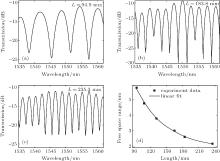 | Fig. 2. Transmission spectrum of the up-taper-core-offset-based filter with fiber length L = 94.9 (a), 183.8 (b), 235.3 mm (c), and (d) the relationship between FSR and L. |
Although the comb filter shows a good property in the C-band, there is also a slight fluctuation in the transmission spectrum. This phenomenon is caused mainly by the interferences between the high-order modes and the fundamental mode. To analyze the number and power distribution of the interference modes, the transmission spectra in Fig. 2 are Fourier-transformed to obtain the spatial frequency spectra of the interference patterns. The spatial frequency spectra are shown in Fig. 3(a). The dominant peak at zero corresponds to the fundamental mode LP01, and the other peaks correspond to the high-order modes. There is only one prominent minor peak in Fig. 3(a), which indicates that only one high-order mode is excited effectively and interferes with the fundamental mode. However, there are also some feeble peaks in Fig. 3(a) which relate to other high-order modes. The interference between these high-order modes and the fundamental mode is slight and modifies the envelope of the transmission spectrum as shown in Fig. 2.
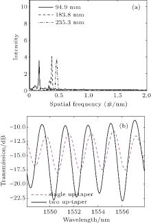 | Fig. 3. (a) Spatial frequency spectra of the comb filter with different fiber lengths, (b) transmission spectra of the filter with single and two up-tapers. |
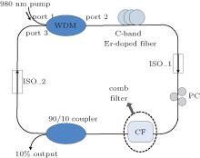
As expressed above, the comb filter based on the cascaded up-tapers-core-offset structure can be used as a wavelength selector to fabricate the multi-wavelength fiber laser. The configuration of the proposed laser is shown in Fig. 4. Here a 980-nm laser diode with a power of 150 mW is used to pump the laser. The pump laser is incident into the cavity through a 980/1550 wavelength division multiplexer (WDM). The other port of the WDM(port2) is fusion-spliced with a 4-m-long in-house-fabricated erbium-doped fiber (EDF), whose absorption coefficient is 16 dB/m at 1530 nm. Then the EDF is spliced with the up-taper-core-offset-based comb filter, which is used to serve as the wavelength select mechanism. The filter length used in our laser is 235.3 mm, with the FSR of 2.18 nm. The insertion loss of this filter is about 11 dB and the transmission spectrum is shown in Fig. 2(c). Here we should point out that the polarization dependence of the proposed filter is reduced in the cavity due to the asymmetry of the core-offset structure, and a polarization controller (PC) is inserted in front of the filter to control the polarization statement. The PC can diversify the polarization states of different wavelengths in the EDF through wavelength-dependent polarization rotation and introduce wavelength-dependent gain and loss. Consequently, a polarization hole burning (PHB) effect is introduced into the cavity, which will reduce the homogeneous line-width of the EDF.[21] The output of the filter is then spliced with a 10/90 fiber coupler whose 10% port is used to monitor the output of the laser, and the 90% port is spliced with port 3 of the WDM to make the light transmit back to the cavity. Here two isolators (ISO) are inserted into the cavity to suppress the undesired reflection.
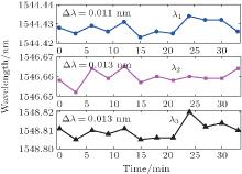
By adjusting the PC, the laser can be made to operate in stable single-, dual-, and three-wavelength lasing states under the invariable pumped power at room temperature. The output spectrum with three wavelengths is shown in Fig. 5. The wavelengths are 1544.431 nm (λ 1), 1546.657 nm (λ 2), and 1548.807 nm (λ 3). The lasing wavelengths are determined by the transmission peaks of the comb filter. The wavelength intervals are 2.226 nm between the first peak and the second peak, and 2.15 nm between the second peak and the third peak. Here we should point out that the lasing wavelength spacing of the oscillation operations is not precisely matched with the transmission peaks spacing of the comb filter. This phenomenon is caused mainly by the spectral hole burning (SHB) effect. The SHB effect can be influenced when we adjust the PC, which will affect the gain spectrum of the laser.[21]
The measured signal-to-noise ratio (SNR) is better than 45 dB, and the 3-dB bandwidths are 0.035 nm, 0.033 nm, and 0.035 nm for the three wavelengths. In order to test the stability of the laser, the output spectrum is recorded repeatedly for more than half an hour with the recording interval of three minutes. The results are shown in Figs. 6 and 7. The results show that the laser exhibits a high stability within the measured time with a peak power and lasing wavelength fluctuation of less than 0.9 dB and 0.013 nm for these three wavelengths. The detailed fluctuation for each wavelength is marked in these figures. Here we should point out that there are only three wavelengths oscillating in the cavity at most. We think that this is mainly due to the unequal EDF gain. In addition, the property of the home-made PC also will influence the number of lasing wavelengths because the polarization states of the different lasing wavelengths cannot be accurately adjusted.[21]
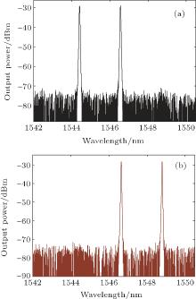
By adjusting the state of the PC, we can control the polarization state in the ring cavity. Then we can adjust the polarization-dependent loss for the three lasing wavelengths of λ 1, λ 2, and λ 3. If the polarization-dependent loss for one lasing wavelength is big enough, this lasing wavelength will be suppressed. As a result, the lasing wavelength number can be controlled and a switchable fiber laser with single- and dual-wavelengths can be achieved. Figure 8 shows the output spectra of the laser with dual-wavelength. Figure 8(a) shows the output spectrum with the lasing wavelengths of 1544.418 nm and 1546.566 nm and figure 8(b) shows the output spectrum with the lasing wavelengths of 1546.658 nm and 1548.806 nm. In order to test the stability of the laser operating in dual-wavelength, the output spectrum is recorded repeatedly 12 times in 3-min intervals for more than half an hour. The results show that both of the two dual-wavelength lasers are highly stable. The measured peak power and lasing wavelength fluctuation for each of the two dual-wavelength lasers are less than 1 dB and 0.015 nm, respectively.
Adjusting the PC continuously, a single-wavelength laser can be achieved in this experiment. The single-wavelength can be controlled to oscillate at each wavelength among the three wavelengths by adjusting the PC. The superimposed spectra of the laser with single-wavelength are shown in Fig. 9. The output laser wavelengths are 1544.301 nm, 1546.484 nm, and 1548.820 nm for these three single-wavelength lasers. Here we should point out that the wavelengths are not precisely matched with the three-wavelength output results. This phenomenon is caused mainly by the SHB and PHB effect. In order to illustrate the position relations of each lasing wavelength, we plot these three single-wavelength lasers in the same figure in different colors as shown in Fig. 9. The stabilities of the three single-wavelength lasers are also monitored in more than half an hour. The power and wavelength fluctuation are less than 0.7 dB and 0.015 nm for each of the three wavelengths respectively.
Here, we should point out that the up-taper-core-offset structure is polarization-dependent. By adjusting the PC, we can gain a dual-wavelength fiber laser with two different polarization stations. The output spectrum is shown in Fig. 10. The out wavelengths are 1548.689 nm and 1548.820 nm, with a wavelength spacing of 0.131 nm. In addition, by adjusting the PC, we can suppress one of the two polarization stations and the dual-wavelength fiber laser can be switched to single-wavelength. The output spectra of the fiber laser under different polarizations are shown in Fig. 11.
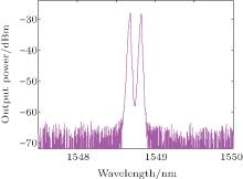 | Fig. 10. Output spectrum of the laser with dual-wavelength operation. |
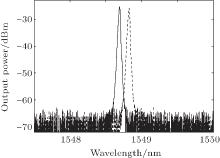 | Fig. 11. Output spectra of the laser under different polarization stations. |
In addition, by adjusting the fiber length of the comb filter, we can control the FSR of the filter. In this condition, we can gain a fiber laser with more lasing wavelengths. Figure 12 shows the output spectrum of the laser with a filter length of 304.3 mm, whose FSR is 1.85 nm. As shown in Fig. 12, we can gain a four-wavelength stabile output.
 | Fig. 12. Output spectrum with four lasing wavelengths. |
We proposed a comb filter based on a cascaded up-tapers and core-offset jointing point. Here the two cascaded up-tapers are used as a cladding exciting component, and the core-offset jointing point is used to act as the interference component. This novel fiber filter shows a nice filter property in the spectrum range of the C-band with a measured extinction ratio of better than 12 dB. On this basis, we fabricate a switchable multi-wavelength erbium-doped fiber laser. By adjusting the state of the PC, a switchable fiber laser with single-, dual-, and three-wavelengths is achieved in this experiment. The laser has an SNR of better than 45 dB and shows a high stability at room temperature within the measured time. In addition, by adjusting the fiber length of the comb filter, we can gain a fiber laser with more lasing wavelengths.
| 1 |
|
| 2 |
|
| 3 |
|
| 4 |
|
| 5 |
|
| 6 |
|
| 7 |
|
| 8 |
|
| 9 |
|
| 10 |
|
| 11 |
|
| 12 |
|
| 13 |
|
| 14 |
|
| 15 |
|
| 16 |
|
| 17 |
|
| 18 |
|
| 19 |
|
| 20 |
|
| 21 |
|


