†Corresponding author. E-mail: han xiaoying@iapcm.ac.cn
*Project supported by the National Basic Research Program of China (Grant Nos. 2011CB921501 and 2013CB922200), the National Natural Science Foundation of China (Grant Nos. 11274035, 11275029, 11328401, 11371218, 11474031, 11474032, and 11474034), and the Foundation of Development of Science and Technology of Chinese Academy of Engineering Physics (Grant Nos. 2013A0102005 and 2014A0102005).
A method to deal with the electron impact excitation cross sections of an atom from low to high incident energies are presented. This method combines the partial wave method and the first Born approximation (FBA), i.e., replacing the several lowest partial wave cross sections of the total cross sections within FBA by the corresponding exact partial wave cross sections. A new set of codes are developed to calculate the FBA partial wave cross sections. Using this method, the convergent e–He collision cross sections of optical-forbidden and optical-allowed transitions at low to high incident energies are obtained. The calculation results demonstrate the validity and efficiency of the method.
Atomic data of the electron impact excitation process are indispensable in many fields, including radiation physics, [1] plasma physics, [2] atmospheric physics, [3] and astrophysics.[3– 5] Helium is an abundant element in the universe, whose electron impact excitation cross sections are important physical parameters for diagnosing helium abundances in astrophysics.[6– 10]
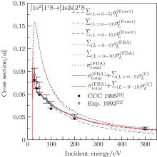
With only two electrons, the helium atom provides a testing ground for developing a general method to deal with electron scattering with complex atoms or ions. Many calculations of electron– helium scattering have been performed experimentally (see review articles[11– 14] and the references therein) and theoretically.[15– 22] However, most of those studies mainly focused on the cross sections near the excitation threshold. Reference [21] (Fursa and Bray 1995) applied the convergent close-coupling (CCC) method to calculate e– He scattering cross section excited from the ground state in the incident energy range from 1.5 eV to 500 eV, where the overall agreement with the experimental data[23] is good, but without a detailed resonance structure.
It is known that the excitation cross sections of an atom impacted by low-energy electron can be dealt with by the partial wave method using R-matrix codes.[24– 31] At the high incident energy, the first Born approximation (FBA) is applicable and the generalized oscillator strength (GOS, i.e. the differential cross sections) can be calculated, e.g., by the codes we developed from the traditional R-matrix codes.[32, 33] To calculate the electron impact excitation cross sections of the atom at intermediate incident energy is still a difficult task, especially for optical-allowed transition, since here FBA is inapplicable and a huge number of partial wave cross sections (PWCS’ s) need to be accounted.
In this work, an approach to deal with the electron impact excitation cross sections of atom at low to high incident energies in a consistent way are presented and validated by the e– He collision calculations. More specifically, the exact PWCS’ s and the PWCS’ s within FBA of e– He collision in the whole energy range (from low to high incident energies) are calculated for [1s2]11S → [1s2s]21S and [1s2]11S → [1s2p]21P transitions. The exact PWCS’ s are calculated by using the traditional R-matrix method. To calculate the PWCS’ s within FBA, a new set of codes are developed based on the traditional R-matrix codes. The calculation results show that the two kinds of PWCS’ s decrease with the increasing angular momentum L and the increasing incident energy. The comparisons between the two kinds of PWCS’ s manifest that the exact and FBA PWCS’ s merge together gradually with the increasing L. The two features give some hint that the difference between the exact and FBA total cross sections mainly originate from the lowest several PWCS’ s. Thus the approach of combining the partial wave method and FBA is presented, i.e., replacing a few FBA PWCS’ s (L < Lcut) of the FBA total cross sections by the corresponding exact PWCS’ s. The convergent total cross sections of e– He collision for monopole and dipole transitions at low to high incident energies are obtained by using this method. Our calculation results agree with the previous experimental measurement[23] and CCC calculation results[21] overall. Moreover, in our calculations the resonance structures near the excitation threshold are displayed. Therefore, the e– He collision calculations demonstrate that the excitation cross sections of an atom impacted by electrons at low to high incident energies can be dealt with efficiently in a consistent way by combining the partial wave method and FBA.
Since the detailed descriptions of the R-matrix method to deal with the electron– atom collision process have been presented elsewhere, [24– 31] a brief outline will be given here. This method begins by partitioning the subconfiguration space of the colliding electron into two regions by a sphere of radius a centered on the nucleus. The value of a is chosen such that the exchange interactions between the colliding electron and the other target electrons are negligible for r > a, where r is the distance of the colliding electron relative to the centroid of the target atom. Thus in the external region (r ≥ a), the colliding electron mainly feels a long-range static polarization potentials.
Within the reaction zone r ≤ a, the interactions between the colliding electron and the target electrons involve electron exchange and correlation interactions, which is a many-body problem and is solved variationally as a whole to obtain the logarithmic derivative boundary matrix R(E). Therefore, in the reaction-zone the electron correlations for the (N + 1)-electron system including the target atom and a colliding electron are calculated adequately by the variational method. The wavefunction Ψ for the (N + 1)-electron system of eigen-energy E in the reaction zone are expanded as

where Ψ k are the energy-independent bases, which are expanded by the following way

where A is the antisymmetrization operator which accounts for the electron exchange between the target electrons and the colliding electron. Φ i are the channel wavefunctions obtained by coupling the N-electron target wave functions with the angular momentum and spin of the colliding electron. uij are the continuum orbitals. ϕ j are (N + 1)-electron wave functions formed from the bound-type orbitals to ensure the completeness of the total wave functions and take account of the electron correlations within the reaction zone. The coefficients aijk and bjk are obtained by diagonalizing the Hamiltonian matrix of the (N + 1)-electron system. Using the R-matrix method, we can deal with the interactions between the target electrons and the colliding electron in various channels within the reaction zone.
In an electron impact excitation process, the differential cross section dσ /dΩ is equal to (k′ /k)| f(k̂ ′ )| 2 (atomic units are used throughout the paper if not specified). Here f(k̂ ′ ) is the scattering amplitude, which can be calculated by the following formula, [34]

where Ti→ j is the T-matrix. k (k′ ) and χ (χ ′ ) are the wave vector and spin wave function of the initial (final) state of the impact electron. Φ i(L̃ S̃ π ̃ ) and Φ j(L̃ ′ S̃ ′ π ̃ ′ ) are the initial- and final-state wave functions of the target with the definite angular momentum L̃ (L̃ ′ ), spin S̃ (S̃ ′ ), and parity π ̃ (π ̃ ′ ). | eik· rχ , Φ (L̃ S̃ π ̃ )〉 is the wave function of an (N + 1)-electron system. Ψ + characterizes the asymptotic behavior of the initial state for the (N + 1)-electron system. V(r1 … rN, r) is the interaction operator between the impact electron and the target, which is equal to 

 | (4) |
here the direction of incident electron is defined as the ẑ axis. l (l′ ) and s (s′ ) are the angular momentum and spin of the impact (scattered) electron. The total angular momentum L, spin S, and parity π of the (N + 1)-electron system are good quantum numbers in an electron impact process. 

According to Bethe theory, [36, 37] if the incident energy of the impact electron is high enough, the asymptotic wave function Ψ + of the (N + 1)-electron system can be evaluated by | eik· rχ , Φ i(L̃ S̃ π ̃ )〉 within FBA, [38] and the corresponding FBA amplitude is

where 
The generalized oscillator strength (GOS) Fi→ j(Δ E, K) of the target is defined as,

From Eq. (6), we can see that the accuracy of GOS is determined by the accuracy of the target wave function Φ (L̃ S̃ π ̃ ). Moreover, in the limit of K → 0, GOS is equal to the optical oscillator strength (OOS), which will be useful to test the accuracy of the calculated GOS by using the optical experimental measurement. In our previous work, [32] the high precision GOS of helium excited from the ground state to n1S, n1P, n1D (n → ∞ ) and adjacent continuum states are calculated by using our developed codes.
Within FBA, the relation between the differential cross section 


After performing the summation of the final state and the average of the initial state, i.e. the integration of k̂ ′ , and the sum of M̃ ′ L̃ ′ , M̃ ′ S̃ ′ , and m′ s′ , and the average over k̂ , M̃ L̃ , M̃ S̃ , and ms, we obtain the FBA total cross sections 
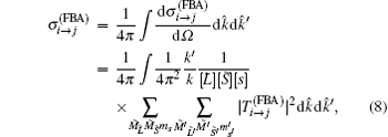
where [L̃ ] means 2L̃ + 1 and 

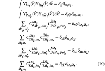
According to the orthogonality of the Clebsch– Gordon coefficient and spherical harmonic functions, we obtain
So the total cross section within FBA is
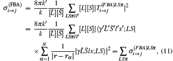
where γ represents all the other information to define the target state uniquely. Based on the traditional R-matrix codes we develop a new set of codes to calculate the PWCS’ s within FBA presented in formula (11). In this work, we adopt the same set of orbital bases, including spectroscopy orbitals 1s, 2s, 2p, 3s, 3p, 3d and pseudo-orbitals 


The difference between the exact PWCS and the FBA PWCS is

If 


It means that a few lowest FBA PWCS’ s (L ≤ Lcut) of the total cross sections within FBA are replaced by the corresponding exact PWCS’ s. Beyond Lcut the difference between the exact and FBA PWCS’ s is negligible. This approach is anticipated to be more efficient than the partial wave method to calculate the total cross sections at intermediate incident energy, especially for the optical-allowed transition.
Figure 1 shows the comparisons between our calculated eight lowest PWCS’ s (L = 0 ∼ 7) for [1s2]11S → [1s2s]21S transition according to the formula (4) (labeled as “ Exact” ) and the formula (11) (labeled as “ FBA” ) respectively. In Fig. 1, it can be seen that the two kinds of PWCS’ s decrease fast with the increasing angular momentum L and the increasing incident energy. The maximum of the two kinds of PWCS’ s for L = 7 are only about 10% of those for L = 0 respectively. The two kinds of PWCS curves gradually merge together with the increasing L at the intermediate and high incident energies (> 200 eV). So the main contribution of the differences between 

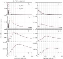 | Fig. 1. The comparisons between the PWCS’ s (L = 0– 7) for [1s2]11S → [1s2s]21S transition calculated according to the formula (4) (solid line labeled as “ Exact” ) and the formula (11) (dashed line labeled as “ FBA” ) respectively. |
Figure 2 shows the total cross sections for [1s2]11S → [1s2s]21S transition calculated by partial wave method and FBA method respectively. In Fig. 2, at the low incident energies (from threshold to 50 eV) the blue, red, and black dashed lines (corresponding to the summations of the lowest 6, 11, and 16 


For more clarity, figure 3 shows the ratios of the calculated total cross sections by different methods in Fig. 2 relative to 

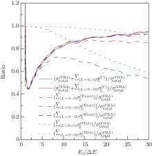 | Fig. 3. The ratios of the calculated total cross section curves by the different methods in Fig. 2 relative to the total cross sections within FBA. |
In Fig. 3, the blue dashed line (the summation of the 6 exact PWCS’ s) agree with the red solid lines in the range of Ei/Δ E < 3, the red dashed line (the summation of the 11 exact PWCS’ s) agree with the red solid lines until to Ei/Δ E ∼ 12. This demonstrates that at the high incident energies (Ei/Δ E > 12) more PWCS’ s need to be accounted for the total cross sections. The red and blue dotted lines (the summation of the FBA PWCS’ s) start from one at the threshold and then become lower than one gradually. This also means that with the increasing incident energies more FBA PWCS’ s need to be accounted for in the convergent FBA total cross sections.
Figure 4 shows the comparisons between our calculated eight lowest PWCS’ s (L = 0 ∼ 7) for [1s2]11S → [1s2p]21P transition according to the formula (4) (labeled as “ Exact” ) and the formula (11) (labeled as “ FBA” ) respectively. In Fig. 4, it can be seen that for L > 0 the two kinds of PWCS’ s decrease with the increasing L and the increasing incident energy. The FBA PWCS’ s decrease faster with the increasing L than the exact PWCS’ s. On the other hand, the FBA and exact PWCS curves gradually merge together with the increasing L in the overall energy range. Therefore, the main contribution of the difference between 

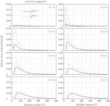 | Fig. 4. The comparisons between the PWCS’ s for [1s2]11S → [1s2p]21P transition calculated according to the formula (4) (solid line labeled as “ Exact” ) and the formula (11) (dashed line labeled as “ FBA” ) respectively. |
Figure 5 shows the total cross sections for [1s2]11S → [1s2p]21P transition calculated by partial wave method and FBA method respectively. In Fig. 5, it can be seen that in the whole incident energy range only the red solid line (i.e., 


To see this more clearly, figure 6 shows the ratio curves of the total cross sections calculated by different methods in Fig. 5 relative to 
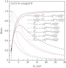 | Fig. 6. The ratios of the calculated total cross section curves by the different methods in Fig. 5 relative to the total cross sections within FBA. |
Finally we would make the following conclusion. A method to deal with the electron atom collision excitation cross sections from low to high incident energies in a consistent way is presented. This method combines the partial wave method and the FBA method, i.e., replacing the lowest several FBA PWCS’ s of the FBA total cross sections by the corresponding exact PWCS’ s. To calculate the FBA PWCS’ s a new set of codes are developed based on the traditional R-matrix codes. The e– He collision calculations demonstrate the validity and the efficiency of the method for optical-allowed and optical-forbidden transitions. More specifically, our calculated exact and FBA PWCS’ s of e– He collision decrease with the increasing angular momentum L and the increasing incident energies. The two kinds of PWCS’ s merge together with the increasing angular momentum L at intermediate and high incident energies. These features manifest that the difference between the exact and FBA total cross sections mainly originates from the lowest several PWCS’ s. Thus the convergent total cross sections at low to high incident energy can be obtained by replacing the several lowest partial wave cross sections of the total cross sections within FBA by the corresponding exact partial wave cross sections. Moreover, using this method the resonance structures of the total cross sections near the threshold are guaranteed since the resonances mainly present in the several lowest exact PWCS’ s near the threshold. Although the CCC method is valid at all incident energies, it concentrates on a single energy at a time and is very time-consuming to exhibit the resonance structures. The illustrated method in this work, inherited from the R-matrix method, has the ability to generate accurate results on a fine energy mesh after the single time consuming step of solving the problem within the ‘ inner’ region and is more timesaving and efficient.
| 1 |
|
| 2 |
|
| 3 |
|
| 4 |
|
| 5 |
|
| 6 |
|
| 7 |
|
| 8 |
|
| 9 |
|
| 10 |
|
| 11 |
|
| 12 |
|
| 13 |
|
| 14 |
|
| 15 |
|
| 16 |
|
| 17 |
|
| 18 |
|
| 19 |
|
| 20 |
|
| 21 |
|
| 22 |
|
| 23 |
|
| 24 |
|
| 25 |
|
| 26 |
|
| 27 |
|
| 28 |
|
| 29 |
|
| 30 |
|
| 31 |
|
| 32 |
|
| 33 |
|
| 34 |
|
| 35 |
|
| 36 |
|
| 37 |
|
| 38 |
|


