†Corresponding author. E-mail: jingfeng09@sina.cn
*Project supported by the National Natural Science Foundation of China (Grant No. 61308040) and the National High Technology Research and Development Program of China (Grant No. 2013AA8043047).
Due to laser-induced damage, the aperture of optics is one of the main factors limiting the output capability of high-power laser facilities. Because of the general difficulty in achieving large-aperture optics, an alternative solution is to tile some small-aperture ones together. We propose an accurate, stable, and automatic method of array element tiling and verify it on a double-pass 1 × 2 tiled-grating compressor in the XG-III laser facility. The test results show the accuracy and stability of the method. This research provides an efficient way to obtain large-aperture optics for high-power laser facilities.
The high-power laser can produce ultra-short and ultra-strong pulses, and is widely used in many fields, for example, the fast ignition in inertial confinement fusion, [1] the study of laser– matter interactions, [2] and research into x-ray sources.[3] Due to laser-induced damage, the output capability of high-power laser facilities is mainly limited by the apertures of optics, including the non-linear crystal, compression grating and focusing terminal. So large-aperture optics is required to improve the output capability of high-power laser facilities. However, it is quite difficult to manufacture large-aperture optics with the state-of-the-art technology, an alternative solution is to tile some small-aperture ones together.
To obtain a large-aperture non-linear crystal, researchers tried to tile nine potassium dihydrogen phosphate (KDP) crystals together in the Nova laser facility in 1982.[4] In 2008, researchers from Osaka University proposed a tolerance range for the tiling errors of four KDP crystals.[5] With regard to the grating tiling, Mazzacurati et al. analyzed the possibility in 1990.[6] In 1998, Zhang et al. proposed an array grating compressor to scale the output energy by increasing the gratings’ apertures in the compressor.[7] At present, many high-power laser facilities use the tiling technology to obtain a large-aperture grating, e.g., America’ s Omega-EP facility, [8] Japan’ s Firex-I facility, [9] and China’ s SG-II petawatt facility.[10] In the planned conceptual design of the multinational cooperation laser facility HiPER, a tiling terminal similar to a large tiling telescope was proposed to realize the simultaneous focus of 24 beams.[11] The fast ignition pulse of America’ s national ignition facility (NIF) also used a similar technology.[12] To avoid the influence of the tiling errors on the output pulses, the array element should be tiled with high accuracy and stability. This study proposes an accurate, stable, and automatic method to tile the array element. This method uses capacitance displacement sensors to detect the pose of the array element and a proportional-integral-derivative (PID) control algorithm to lock the pose. The proposed method is verified on a double-pass 1 × 2 tiled-grating compressor in the XG-III laser facility.
In the ideal tiling of the array element, all the sub-elements lie on an ideal plane or a curved surface and can be treated as a complete large-aperture element. However, there will be some inevitable misalignment errors among the sub-elements. The most typical errors include rotation errors around axes x and y (tip θ x and tilt θ y, respectively), and longitudinal shift dz, as shown in Fig. 1. Of course, for different optics, there are also other tiling requirements, such as consistency of the matching angles of the non-linear crystals, and the groove parallel for the gratings. Specific errors will not be discussed in this paper.
It is assumed that the tiled array element is composed of a static unit and a dynamic unit. The static unit is mounted on the support frame as the tiling base, while the dynamic unit is driven and supported by a movement mechanism. Moreover, we assume that the rotation angles of the dynamic unit around axes x and y are α and β , respectively, and the shift along axis z is dz. The rotational transformation matrices of the coordinate system are


and the translational transformation matrix is

During the adjustment process, the target pose of the dynamic unit is generally known. By calculating the inverse solution according to Eqs. (1)– (3) and the dynamic model of the tiled structure, the output of each driven mechanism can be obtained. By the driven mechanism, the dynamic unit can move to the predetermined position and stay at the expected pose.
The capacitive displacement sensor is a kind of precise measuring instrument. Based on the principle of non-contact capacitance, it can convert a mechanical displacement into a capacitance variation to realize the measurement of the mechanical displacement. Owing to the high resolution (nm), the capacitive displacement sensor is applicable to high accuracy measurement. Qiao et al.[13] and Habara et al.[14] proposed that the capacitive displacement sensor can be used to provide the positional information of one grating with respect to another.
Figure 2 shows the pose lock and control system for the array element based on capacitive displacement sensors. The whole control system, which runs in a closed-loop mode, is comprised of a set of driving mechanisms, several capacitive displacement sensors, and a processor. The capacitive displacement sensors detect the current tiling pose information w of the array element in real-time. The processor conducts the analysis and calculation to acquire the control signal q according to the output of the capacitance displacement sensors. The driving mechanism is the executive component of the system and drives the array element to change pose. Under the effect of q, the tiling error r can be controlled and the pose of the array element can be locked.
Before actual operation, the system should be calibrated to determine the tiling reference state of the array element. The output of the capacitance displacement sensors in this state is taken as the tiling reference wref. With a tiling error among sub-elements, the output wreal of the capacitance displacement sensors varies correspondingly with the pose change of the array element. Therefore, the tiling state of the array element can be deduced according to the output of the capacitive displacement sensors. The pose lock and control of the array element is realized by a PID control algorithm

where qk+ 1 and qk are the (k + 1)-th and the k-th control signals, respectively; S is the mapping matrix between the state change of the capacitance displacement sensors and the control signal, which can be obtained by theoretical calculation or actual measurement; and a1 and a2 are the control factors, which can be set and optimized according to the real condition. As the algorithm runs, the output of the capacitance displacement sensors converges towards the tiling reference wref.
The tiled grating compressor of the XG-III laser facility[15] is used for verification. The tiled-grating compressor is constituted by TGA1 and TGA2, where TGA1 consists of sub-gratings G11 and G12, and TGA2 is composed of sub-gratings G21 and G22. G11 and G21 are static gratings, while G12 and G22 are dynamic gratings. The experimental setup is shown in Fig. 3.
After reaching TGA1, the main laser (the red beam) is diffracted to TGA2 which is in parallel with TGA1. Then it is further diffracted by TGA2. After that, the diffracted beam is reflected by M4. By adjusting M4, the beam is reflected along the incident direction of the beam horizontally and deviated by a small angle (about 1° ) with the incident beam vertically. After being reflected by M5 and M6, it enters the beam reducer composed of L3 and L4. The reduced beam is focused by L5, and the far-field pattern is recorded by CCD2. A micro-objective lens is used here for expanding the far-field pattern.
The red beam in the figure is the main laser, while the blue one is the monitoring laser. The monitoring laser is mainly used to calibrate the system and determine the tiling reference. The monitoring laser and the main laser meet the match relation equations proposed by our group, [16] and their far-field patterns vary in the same way with the tiling errors between the tiled-gratings. In the calibration process, the tiling errors are separated by the 0th order and the 1st order diffraction far-field patterns of the monitoring laser. When the tiling errors are corrected, the far-field pattern of the main laser is the reference pattern. For convenience, a continuous laser with the same wavelength is used as the main laser.
Figure 4 shows the far-field patterns before and after tiling TGA1 and TGA2 of the main laser. It can be seen that after tiling TGA1 and TGA2, the far-field pattern has a much higher intensity. The red and blue curves in Fig. 4(b) show the normalized intensity profiles in the horizontal and vertical directions, respectively.
To test the accuracy of the proposed method, the cross-correlation algorithm below is used to analyze the similarity between the traced far-field pattern and the reference far-field pattern

where

R(u, v) is the cross-correlation coefficient; Iref is the reference pattern; Ireal is the traced pattern; (N, N) refers to the size of the reference pattern; Ireal(u + i, v + j) is the data from row u + i and column v + j in the traced pattern; and Iref(i, j) is the data from row i and column j in the reference pattern. In the calculation, the Iref of N × N moves over the greater Ireal of M × M. As R(u, v) is maximal where Ireal and Iref are the most similar, it can be used to characterize the similarity between the two patterns. Moreover, a long-term observation of the far-field pattern is performed to test the stability.
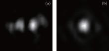
Figure 5 shows the far-field patterns of the main laser with and without misalignment errors among tiled-gratings. It is found that the cross-correlation coefficient of the two far-field patterns is 77%, i.e., there is a similarity of 77% between the two far-field patterns. When the traced pattern is exactly the same as the reference pattern, R(u, v) is equal to 100%.
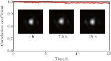
The far-field patterns are acquired at a frequency of 30 f/h for 15 h. Figure 6 shows the variation in cross-correlation coefficient between the traced far-field pattern and the reference far-field pattern. The cross-correlation coefficient is always greater than 98% in the 15 h, and is greater than 99% for most of the time (58.4%). Figure 6 also shows the far-field patterns at 0 h, 7.5 h, and 15 h. They are very similar to each other. These results show that within 15 h, the array element tiling system has high accuracy and stability.
To improve the output capability of high-power laser facilities, we propose an accurate, stable, and automatic method of array element tiling. This method uses capacitance displacement sensors to detect the pose of the array element and a PID control algorithm to lock the pose of the array element. The method is verified on a double-pass 1 × 2 tiled-grating compressor in the XG-III laser facility. The test results prove that the far-field pattern achieves a similarity of 98% with the reference far-field pattern within 15 h, and most of the time (58.4%), the similarity is greater than 99%. It can be seen that this proposed method is both accurate and stable. This research provides an efficient way to obtain large-aperture optics for high-power laser facilities.
| 1 |
|
| 2 |
|
| 3 |
|
| 4 |
|
| 5 |
|
| 6 |
|
| 7 |
|
| 8 |
|
| 9 |
|
| 10 |
|
| 11 |
|
| 12 |
|
| 13 |
|
| 14 |
|
| 15 |
|
| 16 |
|


