Shen Yang-Wu, Ke De-Ping†, Sun Yuan-Zhang, Daniel Kirschen, Wang Yi-Shen, Hu Yuan-Chao. A novel transient rotor current control scheme of a doubly-fed induction generator equipped with superconducting magnetic energy storage for voltage and frequency support. Chinese Physics B, 24(7): 070201
Permissions
A novel transient rotor current control scheme of a doubly-fed induction generator equipped with superconducting magnetic energy storage for voltage and frequency support
Shen Yang-Wua), Ke De-Ping†a), Sun Yuan-Zhanga), Daniel Kirschenb), Wang Yi-Shenb), Hu Yuan-Chaoa)
School of Electrical Engineering, Wuhan University, Wuhan 430072, China
Department of Electrical Engineering, University of Washington, Seattle, Washington, USA
*Project supported by the National Natural Science Foundation of China (Grant No. 51307124) and the Major Program of the National Natural Science Foundation of China (Grant No. 51190105).
Abstract
A novel transient rotor current control scheme is proposed in this paper for a doubly-fed induction generator (DFIG) equipped with a superconducting magnetic energy storage (SMES) device to enhance its transient voltage and frequency support capacity during grid faults. The SMES connected to the DC-link capacitor of the DFIG is controlled to regulate the transient dc-link voltage so that the whole capacity of the grid side converter (GSC) is dedicated to injecting reactive power to the grid for the transient voltage support. However, the rotor-side converter (RSC) has different control tasks for different periods of the grid fault. Firstly, for Period I, the RSC injects the demagnetizing current to ensure the controllability of the rotor voltage. Then, since the dc stator flux degenerates rapidly in Period II, the required demagnetizing current is low in Period II and the RSC uses the spare capacity to additionally generate the reactive (priority) and active current so that the transient voltage capability is corroborated and the DFIG also positively responds to the system frequency dynamic at the earliest time. Finally, a small amount of demagnetizing current is provided after the fault clearance. Most of the RSC capacity is used to inject the active current to further support the frequency recovery of the system. Simulations are carried out on a simple power system with a wind farm. Comparisons with other commonly used control methods are performed to validate the proposed control method.
PACS:
02.30.Yy; 88.80.fj; 88.50.–k; 84.60.–h
Keyword:
doubly-fed induction generator; transient rotor current control; superconducting magnetic energy storage; voltage support
The utilization of renewable sources for power systems has experienced rapid growth in recent years.[1– 3] As one of the most promising approaches to solving the energy crisis, wind power harnessing techniques have been under extensive study in this century.[4– 10] For many wind farms, doubly-fed induction generator (DFIG) based wind turbines are used. However, DFIG is very sensitive to grid disturbances, especially those causing a sudden drop of the DFIG terminal voltage. During such a fault, the DFIG may be disconnected from the grid to protect its rotor-side converter (RSC) and dc-link capacitor from damage because of the emergence of overcurrent in the rotor circuit and overvoltage in the dc-link capacitor. Hence, the conventional crowbar circuit which directly short circuits the rotor during a grid fault via an external resistor is commonly suggested to protect the DFIG.[11] Despite the fact that the crowbar method is comparatively simple yet reliable, its weakness is also apparent, e.g., loss of the controllability of the stator active power and consumption of a large amount of reactive power during the fault period. Many researchers have tried various advanced approaches implemented on the RSC to solve this problem. Typically, a new low voltage ride through (LVRT) control strategy based on flux linkage tracking was investigated in Ref. [12]. The rotor flux linkage was controlled to track a reduced fraction of the varying stator flux linkage so as to decrease the rotor current during the fault. Another solution to the LVRT issue is to deploy additional hardware, such as energy storage devices (ESDs)[13] or a DC/DC chopper with a resistor across the dc bus of the converter, attached to the DFIG to improve its LVRT capability.
With the increased wind power penetration, modern grid codes require that the DFIGs based wind farms can not only survive during external faults, but also have the capability to contribute to the network transient voltage and frequency support. Several control strategies focusing on the enhancement of the transient behaviors of the DFIG have been proposed in recent years. However, most of the existing literature only solves either the transient voltage support issue or the frequency support issue, and few present a control strategy which fully exerts the capabilities of the ESD equipped to the DFIG to simultaneously fulfill the two control objectives. Therefore, based on a comprehensive review of relevant literature, this paper proposes an elaborated transient rotor current scheme of the DFIG for upgrading both the transient voltage and frequency support capabilities during grid faults by connecting a SMES based ESD to the dc-link of the DFIG (DFIG-SMES). In particular, the SMES is controlled to regulate the dc-link voltage so that the grid side converter (GSC) can be free from such tasks during the transient and it dedicates its entire capacity to injecting reactive power to the grid for the initial voltage support and also assistance of the terminal voltage recovery after the clearance of the grid fault. Moreover, different control objectives for three different periods of the grid fault are designed for the RSC. Firstly, the demagnetizing current control is employed for the RSC in Period I to suppress the transient surge of the rotor current and help the DFIG back to its control region. Then, since the dc component of the stator flux decays rapidly with the demagnetizing current control, the active and reactive current is also added to the rotor current in Period II to provide the initial grid frequency support and further enhance the transient voltage support. Finally, in Period III, the RSC providing demagnetizing and active current and the GSC injecting reactive current are coordinately controlled during a short period after the fault clearance, which remarkably benefits the system post-fault voltage recovery and also improves the grid frequency response dynamics.
This paper is organized as follows: The literature review is presented in Section 2. Section 3 introduces the structure of the DFIG-SMES and the relevant dynamics during grid faults. The overall energy management scheme of the DFIG-SMES is presented in Section 4. Section 5 demonstrates the detailed control design. In Section 6, simulations are carried out to give comprehensive comparisons with other methods. Finally, Section 7 concludes the paper.
2. Literature review
2.1. Transient voltage support
One common requirement of the grid codes for DFIGs is the transient voltage support during the fault period, especially when the DFIG is connected to an electrically weak power network. The grid-side converter (GSC) controlled as a STATCOM to support local voltage during grid disturbance was proposed in Ref. [14]. However, the GSC cannot provide sufficient reactive power due to its limited capacity when the stator voltage dip is severe, and there is still the risk of voltage collapse. In Ref. [15], the RSC was temporarily connected to the stator and it was in parallel with the GSC to deliver reactive power to the grid for transient voltage support. However, in such a manner, the DFIG will act as an induction generator and absorb a large amount of reactive power from the grid which will impair the voltage support capability of the paralleled converters. A fuzzy controller of the DFIG for compensating the PCC voltage sag is proposed in Ref. [16]. However, only a moderate voltage drop of 30% is considered, and the effectiveness of the proposed fuzzy controller is necessarily further verified under much more severe voltage sag conditions due to the limited reactive power provision capability of the DFIG itself. A method in Ref. [17] was proposed to temporarily overload the RSC and GSC with normal capacities to fulfill the transient reactive power control objectives. A multi-stage coordinated reactive power control scheme between the RSC and GSC is proposed in Ref. [18]. Nevertheless, this approach may be limited due to the maximum allowable rotor speed and may become less effective for the large capacity wind turbine with a heavy rotor mass because the rotor acceleration in such a case is slow.
2.2. Frequency voltage support
Network frequency support capability is also rather desirable for the DFIG during grid faults. In the case of the unavailability of conventional units, various control schemes which control the wind turbines (WTs) to provide frequency support via the inertia response and the active power vs. frequency droop control have been reported in many articles.[19] However, these studies were only conducted under the quasi-steady-state condition and the frequency support capabilities were mostly evaluated based on the DFIG model that was dominated by the rotor shaft dynamics. The active power regulation capability of the DFIG during the transient fault is unclear, which is also tightly coupled with its LVRT capability. In Ref. [14], a decoupled-DFIG control strategy was proposed to harness the inertia characteristics of the DFIG to support the system frequency response during the grid fault. Reference [20] proposed coordinated control of a DFIG-based wind farm and HVDC to regulate the system frequency response during grid fault.
3. Structure of the DFIG-SMES system and overall energy management scheme
3.1. Studied system
The structure of the DFIG-ESD system is shown in Fig. 1, and it is readily noted that the only difference from a conventional DFIG structure is that an additional ESD is connected to the dc-link capacitor through a DC/DC converter.
Fig. 1. Structure of the DFIG-SMES. Here, Pr and Qr are rotor output active power and rotor reactive power, respectively; Ps and Qs are stator output active power and rotor reactive power, respectively; Psr and Qsr are the output active and reactive power of GSC, respectively; Pgrid and Qgrid are the total output active and reactive power of DFIF, respectively; PESD is the absorbed power by ESD; Udc is dc-link capacitor voltage.
The ESD installed with the DFIG is used to enhance the transient voltage and frequency support capabilities. Thus, the fundamental physical requirement on the ESD is that it can react rapidly to absorb (or inject) power. Actually, several types of ESDs which react fast enough can be utilized here. Superconducting magnetic energy storage (SMES) has received increasing attention from world-wide power industries because of its significant merits of large energy/power capacity, high efficiency and fast response capability leading to great potential for application in power systems, such as system stability and load flow control.[21, 22] Though the capital cost of the SMES is higher than other types of ESDs such as the supercapacitor[23] and battery, [24] its annual cost (defined as the total life-cycle cost divided by the lifetime) is much lower because of its high efficiency.[25] Moreover, the expensive specialized energy conversion system which is generally required by other ESDs is unnecessary for the SMES used here, and only the DC– DC chopper converter is employed so that overall investment can be considerably reduced.[26] Therefore, the SMES is recommended to play the role of the ESD in this paper.
3.2. Analysis of DFIG during voltage sag
when the static stator and rotor are used as the reference frames, using motor convention, the model of the DFIG can be expressed as[13]
where ψ s and ψ r are the stator and rotor flux, respectively, is and ir are the stator and rotor current, respectively, ω is the slip frequency. vs and vr are the stator and rotor voltage, respectively, and Ls, Lr, and Lm are the stator inductance, rotor inductance, and mutual inductance, respectively.
According to Eq. (2), the rotor flux can be further described as
where σ is the linkage coefficient, and
Substituting Eq. (3) into Eq. (2), the following expression is obtained:
where the superscript r means that the relevant variables are expressed in the rotor reference frame. According to Eq. (5), it is clear that the rotor current is decided by the output voltage of the RSC and the induced electromotive force (EMF).
In normal operation, the amplitude of EMF is around sVsLm/Ls which is proportional to the slip s usually ranging between − 0.3 to 0.3. Therefore, the EMF under normal conditions is relatively small and the RSC can always output the required voltage for the rotor current control. However, the situation changes dramatically in the case of a sudden voltage drop. When an event leading to the three-phase stator voltage dip of depth p (0 < p < 1) occurs, the initial EMF induced by the dc component of the stator flux is Vrdc = Vsp(1 − s)Lm/Ls which is proportional to factor (1 − s) close to 1. For instance, if the DFIG works at the rated pre-fault condition with s = − 0.2 and the three-phase stator voltage dip is 100%, the initial amplitude of Vrdc is 1.2Vs(1 − s)Lm/Ls, which is nearly six times Vrdc under normal conditions. Thus, the EMF will be fairly large and far beyond the range of the voltage output by the RSC. Consequently, the RSC working in the saturated state (output the maximum voltage) will be incapable of controlling the rotor current, which leads to dramatic overcurrent in the rotor circuit. In particular, this rotor current surge carries reasonably large active power flowing through the RSC (via the diodes) to the dc-circuit. Moreover, since the GSC is unable to completely deliver such large reactive power to the grid due to its limited current rating and the low grid voltage, most of the active power (energy) will cumulate in the dc-link capacitor and thus raise the dc-link voltage significantly to an unsecure level. In addition, the cumulative active power in the capacitor will further deteriorate the transient dynamics of the DFIG, and the variation of the dc-link voltage will also affect the control of the rotor current in normal operation.[27]
3.3. Demagnetizing control
As analyzed in the previous subsection, the quite large EMF induced by the dc component of the stator flux during the transient of a three-phase symmetrical grid fault is the essential cause of the subsequent overcurrent and overvoltage matter. If the dc stator flux component can be properly reduced, the EMF will be impaired and the voltage output of the RSC will not offend its limits. Therefore, introducing one current component to the rotor circuit which can produce the stator flux in anti-phase of the original dc stator flux should be an effective way to reduce the EMF. Specifically, when the DFIG is subject to the symmetrical dip of the stator voltage, the rotor flux can be expressed as follows:
where Lsσ and Lrσ are the leakage inductances of the stator and the rotor, respectively; and are the positive sequence- and dc (zero) sequence components of the stator flux respectively.
Since both the current and flux linkage are expressed as the space vectors, according to Eq. (6) we can see that if the rotor current component is just in anti-phase of the dc stator flux, increase of such a rotor current component will decrease the EMF. Hence, this rotor current component is termed the demagnetizing current. Since the EMF component induced by the positive sequence stator flux is small, it is unnecessary to counteract this flux linkage. In consequence, if it is intended to partially eliminate the dc stator flux so as to reduce the EMF, the required demagnetizing current can be calculated based on Eq. (6), as follows:
where kd ∈ (0, 1) denotes the proportion to be eliminated. By setting the control reference of the rotor current to this value, the rotor flux will be as follows:
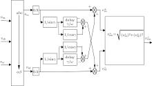
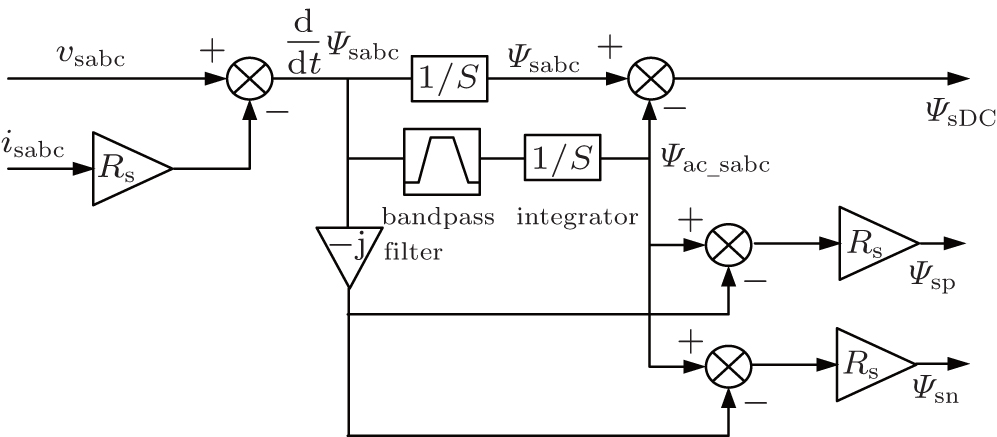
In order to calculate the demagnetizing current control reference, it is necessary to extract the dc, positive-sequence and negative-sequence components from the stator flux. In this paper, a second-order band-pass filter proposed in Ref. [13] is adopted to fulfill such a goal. Figure 2 shows the block diagram of the second-order band-pass filter based stator flux sequence decomposition algorithm. More explanations of the algorithm can be found in Ref. [13].
Fig. 2. The second-order band-pass filter based stator flux component decomposition algorithm. Here, Rs is the stator resistance and 1/S presents the integrator.
Once the dc and negative-sequence components of the stator flux are detected, the control reference of the demagnetizing current to reduce the transient EMF can be calculated based on Eq. (7).
4. Proposed transient energy management scheme of the DFIG-SMES
4.1. Grid code requirements of WTs regarding transient voltage and frequency support
With the worldwide rapid increase of wind power penetration in power systems in recent years, many countries have reinforced their grid codes associated with the integration of wind power generation. The common requirements among these reinforced grid codes regarding the transient voltage and frequency support capabilities of WTs are outlined as follows.
1) Provide transient reactive power to the grid and thus benefit the system voltage stability.
2) Deliver active power to the grid during faults and thus contribute to the improvement of initial frequency response dynamics of the system.
3) Continue the voltage and frequency support after the grid fault clearance. Specifically, the post-fault reactive power support must be maintained for at least 500 ms; and the WTs should supply the active power larger than or equal to 95% of the pre-fault level for 200 ms after the fault clearance.
4.2. Transient power management design for DFIG-SMES
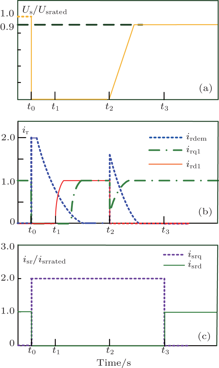
A novel transient power management scheme for the DFIG-SMES is proposed to fulfill the voltage and frequency support requirement. The evolution of the current control reference of the RSC and GSC with the proposed transient power management scheme is shown in Fig. 3. In particular, for the sake of presentation simplicity, the entire grid fault process is assumed to consist of three specific periods according to the transient characteristics of the dc stator flux. Thus, the control objectives are different in these periods, which is discussed in the following.
Fig. 3. Current control references during fault period: (a) stator voltage profile; (b) RSC current; (c) GSC current. Here, Us and Usrated are the actual stator voltage and rated stator voltage of the DFIG, respectively; ir is the rotor current, ird1, irq1, and irdem are the active current component, reactive current component, and demagnetizing current component of ir, respectively; isr and isrrated are the actual current and rated current of grid side converter, respectively; isrd and isrq are the d-axis component and q-axis component of isr, respectively.
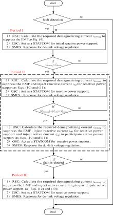
(1) Period I (t0 − t1): the first few cycles after the voltage drops As analyzed in Subsection 3.2, with the conventional control strategy and configuration of DFIG, the quite large EMF will be induced and will cause the saturation of the RSC, finally resulting in the overcurrent and overvoltage issues during severe grid faults. Obviously, it is impossible to regulate the power output of the DFIG to comply with the grid codes with the conventional configuration and control strategy. With the proposed configuration of the DFIG-SMES, the control objectives during Period I are to offer initial reactive power support and help the DFIG back to its control region so that it can strengthen the reactive power support and also participate in the network frequency regulation in the next period. Once the grid fault is detected, the SMES will be responsible for maintaining the dc-link voltage so that there is no risk of overvoltage in the dc-link capacitor. Accordingly, the GSC can be free from the dc-link voltage regulation. Therefore, the GSC can act as an STATCOM and dedicate its whole capacity to injecting reactive current to the grid for the initial reactive power support. Generally, the GSC is capable of carrying the maximum transient current up to 2.0 p.u (with the DFIG capacity and the rated rotor voltage as the basis) during faults in practice.[2] Hence, as shown in Fig. 3(c), the GSC will inject maximum transient reactive current of 2.0 p.u. starting from the occurrence of the fault. On the other hand, a demagnetizing current idemag obtained in Eq. (7) is provided by the RSC to impair the transient EMF so that the RSC can output sufficient voltage for rotor current control and the rotor current will not uncontrollably increase. Therefore, the amplitude control references of the RSC and GSC current in Period I can be set as
The amplitude control reference of the demagnetizing current obtained in Eq. (7) decays along with time due to the degeneration of the dc stator flux. Moreover, it is favorably noted that the injection of idemag can accelerate the decaying process of the dc stator flux.[13] Thus, the final evolution of idemag is shown in Fig. 3(b).
(2) Period II (t1 − t2): the voltage stabilizing stage The DFIG will quickly return to its control region as the fast decay of the dc stator flux during Period I with the demagnetizing control. Thus, the required idemag is small in Period II and there is spare capacity of the RSC that can be further used for transient voltage and frequency support in this period. The RSC works at the priority of transient voltage support. As shown in Fig. 3(b), one reactive current component ird1 is added to the rotor current to assist the GSC for the enhanced voltage support effect. The amplitude of ird1 is increased gradually so that the rotor current (including the demagnetizing and reactive current) is constrained within the current limits of the RSC .
As ird1 reaches 1.0 p.u., another active current component irq1 is also added to the rotor current for grid frequency support. Similarly, irq1 also increases gradually until reaches 1.0 p.u. and during this process the rotor current should never violate the current limits of the RSC. Finally, the whole system evolves to the new steady-state during the fault period. In particular, the SMES always regulates the dc-link voltage while the GSC acts as the STATCOM during this period. Thus, the current control references of the RSC and GSC can be calculated and set as follows:
where
(3) Period III (t2 − t3): the voltage recovery period after the fault clearance During this period, the control objectives of the proposed transient energy management are to help the PCC voltage recovery and contribute to improving the system frequency response dynamics after the fault clearance, as described in Subsection 4.1. Transient EMF will also be induced by the dc component in the stator flux because of the sudden increase of the grid voltage. So the demagnetizing current is also necessarily injected to the rotor circuit by the RSC. Because the EMF here is much lower than that during Period I, the RSC has much free capacity that can be used for promoting the grid frequency recovery. As shown in Fig. 3(b), irq1 increases as idemag decreases. Moreover, the GSC still acts as the STATCOM to support the PCC voltage recovery and the dc-link voltage is regulated by the SMES. The amplitude control references of the RSC and GSC current in Period III are calculated as follows:
where
where irqmax is the optimal pre-fault active current corresponding to the maximum captured wind power. The flowchart explaining the proposed rotor current control strategy of the DFIG-SMES for the transient voltage and frequency support is shown in Fig. 4.
Fig. 4. Flowchart of the proposed rotor current control strategy.
5. Controller design for the DFIG-SMES
In this section, the detailed control design of the DFIG-SMES to improve the reactive power and frequency support capabilities during a serious voltage dip is outlined. The scheme diagram of the proposed control strategy of the DFIG-SMES during the grid fault is shown in Fig. 5. The proposed control system consists of the fault detection module, normal and transient controllers of the SMES module, normal and transient controllers of the GSC module, and normal and transient controllers of the RSC module.
Fig. 5. Overall scheme diagram of the proposed control strategy. Here, wr and wref are real rotor speed and rotor speed references, respectively, θ s, θ r, and θ 1 are the stator, rotor and slip electrical angulars, respectively. ws and wr are stator and rotor angular speeds, respectively.
5.1. Fault detection algorithm
In order to realize rapid switching from the normal controllers to the LVRT controllers, precise and efficient detection of the supply voltage dip is a crucial issue in the implementation of the proposed control strategy for the DFIG.[28, 29] Various fast identification algorithms of the grid voltage dip have been proposed so far.[28, 30] A sequence component decomposition method in Ref. [30], where its accuracy and efficiency in identifying the sequence components of three-phase voltage under balance and unbalance conditions have been verified is adopted in this paper. The block diagram of this method is shown in Fig. 6.
Fig. 6. Block diagram of the fast identification algorithm of voltage sequence components. Here, γ is the delay angular; ω is the grid frequency. vsα and vsβ are the α -axis component and β -axis component of grid voltage in the stationary frame.
In order to show the excellent performance of this detection algorithm, the simulation results with three-phase short circuit faults are shown in Fig. 7. It can be seen from Fig. 7 that the voltage identification of the 10% voltage dip and 85% voltage dip can only cost the time of 2.37 ms and 4.1 ms, respectively. Therefore, the employed method can quickly detect variations in the amplitude of the grid voltage. Specifically, whenever p.u., the algorithm considers a fault detected and thereby the proposed LVRT control strategy of the DFIG-SMES will be activated to protect the DFIG and support the grid voltage and frequency during a transient fault.
Fig. 7. Simulation results of the magnitude estimation of the positive sequence voltage by the sequence component decomposition method. (a) 10 % voltage dip. (b) 85% voltage dip.
5.2. Controllers of SMES
The SMES is connected to the dc-link capacitor via the two-quarter IGBT-based DC/DC chopper converter (Fig. 1). During normal operation, the SMES could be utilized to smooth the active power output of the DFIG. Here, the SMES is controlled to maintain the dc-link voltage during the transient fault so that the GSC can act as the STATCOM for the transient voltage support.
The DC/DC chopper converter is used to regulate the magnitude and the polarity of the voltage (Vsm) across the superconducting coil to realize the charging or discharging modes of the SMES (Fig. 8).[31– 33] It is clearly observed that the coil is charged (Vsm is positive) as the IGBTs are turned on and discharged (Vsm is negative) as the IGBTs are turned off. Over a control cycle, the average value Vsmav of Vsm determining the charging (or discharging) power of the coil is a function of the duty ratio defined as the ratio of the IGBT on-time with respect to the cycle period. Normally, Vsmav increases as the duty ratio increases, and vice versa. If duty ratio is 0.5, Vsmav is zero. Hence, the charging (or discharging) of the SMES can be smoothly controlled by adjusting the duty ratio, as shown in Fig. 9. It is seen that the dc-link voltage is managed by comparing it to the reference to generate the duty ratio via a proportional-integral (PI) block. The duty ratio is applied to the comparator to produce the modulated control signal for the chopper.
Fig. 8. Operating modes of the superconducting coil. (a) Charging, (b) discharging. Here, Vsm and ism are the voltage and current of SMES inductance, respectively.
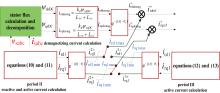
In normal operation, the controllers of the RSC are used to manage the stator active and reactive power in a decoupled manner.[34] During a transient period, the RSC is controlled to satisfy different control objectives at different fault periods as expected in the previous section. Figure 10 illustrates the scheme to generate the rotor current (RSC) control reference. The rotor current reference module consists of three calculation units: the demagnetizing current reference calculation unit for the three periods; the ird1 and irq1 calculation unit for Period II; and the irq1 calculation unit in Period III. Specifically, 75% of the dc component of the stator flux is recommended to be counteracted and the RSC operates at the reactive current control priority, and the maximum reactive and active current is constrained within 1.0 p.u., respectively.
Fig. 10. Rotor current reference calculation during the transient period.
In the positive-sequence (dq)+ synchronous reference frame, the reactive and active current behaves as the dc components while the demagnetizing current acts as the ac component.
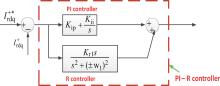
Consequently, the rotor current control reference contains both dc and ac components with the proposed control strategy during the grid fault. However, the conventional PI controller can only regulate the dc component; it is ineffective in regulating the ac component. In order to overcome this issue, a proportional integral (PI) plus resonant (R) controller (PI– R) based transient current controller is employed for RSC during the abnormal grid voltage condition. Figure 11 shows the block diagram of the PI– R controller.
Fig. 11. Control block diagram of the PI– R controller. Here, Kip and Kii are the proportional and integral parameters of PI controller. Krl is the resonant parameters of resonant controller.
With the PI– R controller, the dc current (reactive and active current) is mainly controlled by the PI regulator while the ac current (demagnetizing current) is fully regulated by the R controller. Therefore, the PI– R current controller is capable of regulating the reactive current, the active current, and the demagnetizing current simultaneously. In addition, a single inner current control loop is designed for the RSC in order to obtain a fast response from the demagnetizing and reactive current during the transient period. Accordingly, the block diagrams of the PI– R based RSC current controllers during the transient are shown in Fig. 12.
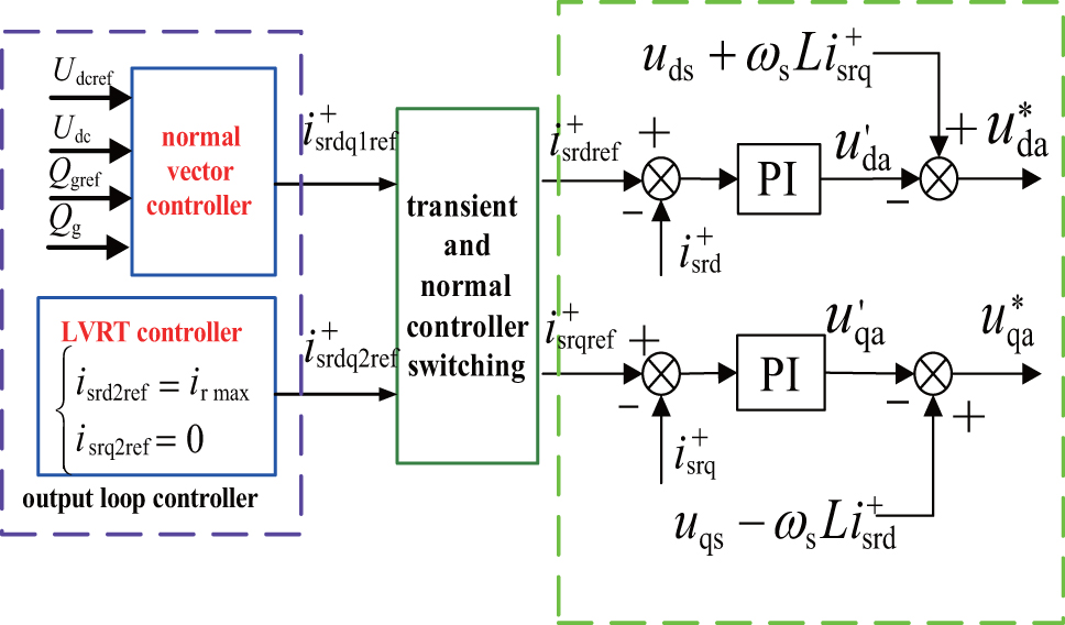
Fig. 12. Controllers of the RSC during normal and transient operation. Here, is the slip angular speed, and are the rotor current references during normal operation and during transient operation, respectively.
The DFIG rotor will temporarily accelerate as a result of the proposed demagnetizing current control strategy during a grid voltage dip. However, the generator under the rated power production has almost no risk of over-speeding caused by the proposed control strategy due to the two facts: 1) when the rotor speed increases beyond the specific allowable value, the pitch angle control will be triggered to lower the converted wind power (accelerating power) so as to effectively prevent the generator rotor from over-speeding; 2) the transient rotor speed acceleration will be very limited because the grid fault duration (accelerating period) is normally quite short.[35] Moreover, it should be stressed that the emergent braking system (mounted to the wind turbine by manufacturers) is definitely necessary to protect the mechanical part of the wind turbine in case of the small probability of incidents occurring, such as extreme wind conditions and serious control system outage.
5.4. Controllers of the GSC
The control objectives of the GSC are to keep the dc-link voltage constant[36– 38] and regulate the reactive power exchange between the GSC and grid during normal operation.
As mentioned in the previous section, the GSC will be devoted to injecting reactive power to the grid for voltage support during the transient fault. To achieve such a goal, a PI– R based current controller is employed for the GSC. The overall vector control scheme of GSC during normal operation and transient operation is shown in Fig. 13. It is seen that the control reference idsref of the active current is set to be zero during the transient period so as to ensure no active power is delivered through the GSC, and then the reference idsrref of the reactive current is set to the value that is equal to its capacity which thus can be fully utilized.
Fig. 13. Controllers of the GSC during normal and transient operation. Here, and are the current references of GSC during normal operation and during transient operation, respectively.
6. Simulations
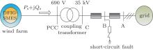
In this section, simulations are carried out on a single-machine-infinite-bus system with a 1.5-MW DFIG based wind farm to validate the proposed method of enhancing the reactive power regulation capability as well as the frequency support capability of the DFIG during faults. Figure 14 shows a schematic diagram of the simulated system with the parameters given as follows.
DFIG rated power = 1.5 MW; stator voltage = 575 V/50 Hz; stator resistance = 0.00736 p.u.; rotor resistance = 0.00523 p.u.; stator leakage inductance = 0.171 p.u.; rotor leakage inductance = 0.156 p.u.; magnetizing inductance = 2.97 p.u.; stator/rotor turns ratio = 0.335; rated rotor speed = 1.2 p.u.; DFIG inertia time constant = 4.5 s; grid-side resistant = 0.003 p.u.; grid-side inductance = 0.3 p.u.; turbine inertia time constant = 2 s; and time constant of pitch servo = 0.225 s.
SMES The inductance of the SMES coil is 5 H, and its rated current is 400 A.
The DFIG-SMES based wind farm is coupled to the 35 kV network through a step-up transformer and integrated to the external grid via 15-km cables. The short circuit ratio (SCR) and X/R ratio of the external grid are defined as 3 and 7, respectively, to simulate a weak external power network.
The DFIG operates at rated pre-fault conditions. At t = 2 s, a three-phase short-circuit fault happens at Bus B of the transmission line and it lasts for 625 ms and significantly decreases the voltage of the wind farm PCC to about 0.15 p.u. The conventional crowbar protection method (Method B) is employed as a comparison to the control design (Method A) proposed in this paper. The external resistance in the crowbar protection is chosen to be 20 times the DFIG rotor resistance. Selected transient waveforms of the DFIG forming the simulation results are compared between the two different methods.
Figure 15 shows the variation of the output voltage of the RSC and the rotor current. It can be seen that both methods can suppress the rotor current quickly and its magnitude is constrained below the current limitation (2.0 p.u.) of the RSC (see Fig. 15(b)). However, with Method B, the output voltage of the RSC increases to a relatively high value because the RSC is protected by the crowbar circuit and thus no demagnetizing current can be injected to the rotor circuit to reduce the transient EMF. In contrast, with the proposed control strategy, the magnitude of the RSC voltage output is obviously constrained which can be observed in Fig. 15(a).
Fig. 15. Variation of output voltage of the RSC and rotor current with Methods A and B: (a) output voltage of RSC; (b) rotor current.
The voltage profiles at the PCC, the reactive power generated respectively by the stator and the GSC is compared between Method A and Method B, and depicted in Fig. 16. When the grid fault is detected at t = t0 and the crowbar protection is employed, the GSC cannot participate in the reactive power support (see Fig. 16(c)) due to the fact that the total capacity of the GSC is used to regulate the dc-link voltage. Moreover, the DFIG temporarily works as an induction generator and absorbs about 0.14 p.u. reactive power from the grid, and the reactive power consumed by the DFIG further exasperates the terminal voltage. Figure 16(a) shows that the DFIG terminal voltage drops to 0.13 p.u. under such a case, which may be unacceptable if considering the grid codes. As a comparison, the proposed control design can drive the GSC to inject 2.0 p.u. (see Fig. 16(d)) reactive current to the grid for initial transient voltage support, which produces about 0.1 p.u. reactive power (see Fig. 16(c)) to the grid. At t = t1, the free capacity of the RSC is also employed to provide reactive power support because the dc component of the stator flux rapidly decays and the required demagnetizing current decreases. Therefore, it can be found in Fig. 16(b) that the stator of the DFIG outputs almost 0.2 p.u. reactive power, which will further boost the voltage at the PCC from 0.16 p.u. to 0.18 p.u. (see Fig. 16(a)). In addition, when the grid fault is cleared at t = t2, Method A continues controlling the GSC to inject reactive power to help the voltage recovery during the period t2 − t3, while Method B causes the DFIG to absorb a large amount of reactive power from the grid during the voltage recovery period. Consequently, the voltage of the PCC is found to recover quite rapidly with the use of Method A, in comparison to the slow voltage recovery process when Method B is employed (Fig. 16(a)).
Fig. 16. Selected transient waveforms: (a) PCC voltage; (b) reactive power output by stator; (c) reactive power output by GSC; (d) q-axis component of GSC current.
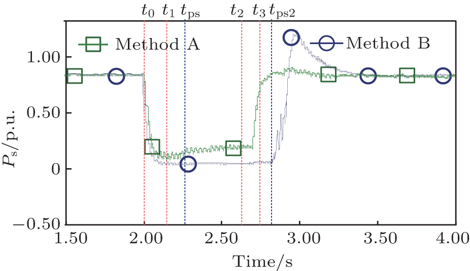
Figure 17 shows the total active power generated by the DFIG with the two methods. It can be observed that with Method B, the active power output by the DFIG is significantly reduced during the entire fault period. However, with Method A, the active current is added to the rotor circuit to control the active power from t = tps because of the significant reduction of the dc component of the stator flux during the time period t0 − tps and that there is free capacity of the RSC that can be employed to control the active power output to participate in the system frequency regulation. Moreover, the active power control cannot recover quickly after the fault clearance because the crowbar action is also activated during t2 to tps2 to suppress the transient rotor current. Apparently, with the proposed configuration and associated control strategy, the active power output of the DFIG can rapidly return to its pre-fault level, which complies well with the grid code requirements.
Fig. 17. Active power output by the DFIG during a transient fault with Methods A and B.
It is noted that although the rotor current can be properly constrained by Method B, the maximum dc-link voltage excurses to almost 1.4 p.u. owing to the limited power transmission capability of the GSC during the grid fault (see Fig. 18(a)), which may cause the disconnection of the DFIG from the grid. By comparison, with Method A, the SMES will efficiently absorb the cumulative power (energy) in the dc-link capacitor, and sometimes it can necessarily inject power to supplement the dc-link voltage, as shown in Fig. 18(b). In consequence, the dc-link voltage is consistently kept at the nominal value during the whole transient period.
Fig. 18. DC-link voltage control capabilities of Methods A and B: (a) dc-link voltage; (b) active power absorbed by SMES.
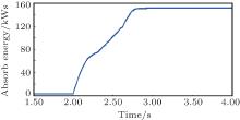
Generally, there is no simple and direct analytical method to calculate the energy capacity of the SMES required for carrying out the proposed control strategy. However, in the studied case it can be numerically estimated by simulating the system dynamics stirred by the 85% voltage dip for 625 ms (the fairly serious fault). By integrating the absorbed power of the SMES over time, the energy stored in the SMES can be calculated. The evolution of the energy is shown in Fig. 19, and comparing the energy in the post-fault steady state and that in the pre-fault steady state can estimate the required energy capacity of the SMES to be around 147.25 kWs.
Fig. 19. The dynamic performance of energy stored in the SMES during the whole grid fault period.
7. Conclusion
In this paper, a novel transient rotor control scheme for a DFIG equipped with a SMES connected to the dc-link capacitor is proposed for upgrading its transient voltage and frequency support capabilities. The SMES is controlled to regulate the dc-link voltage during the transient. Hence, the whole capacity of the GSC is dedicated to injecting reactive power to the grid for transient voltage support. According to the transient characteristics of the dc stator flux, three specific periods are supposed to compose the whole grid fault process. Therefore, for each period the control objective of the RSC is specially designed. The common way to realize the control objectives is to properly set the control references of the demagnetizing, active and reactive current in each period. Thus, the proposed control strategy can guarantee that the rotor current is always under control and no surge will occur during the fault. Moreover, the DFIG-SMES can endeavor to fully support the transient voltage and frequency dynamics at the earliest time. The proposed control design is simulated on a typical DFIG LVRT capability tested system. Furthermore, it compares with the conventional crowbar protection and the results prove its obvious exclusive advantages.
RenL N, LiuF C and JiaoX H2012Acta Phys. Sin. 61060506(in Chinese)[Cited within:1]
9
YangG L and LiH G2009Acta Phys. Sin. 587552(in Chinese)[Cited within:1]
10
LiuY S, FarnellC, BaldaJ C and MantoothH A2015Proceeding of IEEE Applied Power Electronics Conference and ExpositionMarch 15–19, 2015Charlotte, USA697[Cited within:1]
11
ZhangX Q and LiangJ2012Acta Phys. Sin. 6119050(in Chinese)[Cited within:1]
LiuY S, FarnellC, BaldaJ C and MantoothH A2014Proceeding of IEEE Energy Conversion Congress and ExpositionSeptember 14–18, 2014Pittsburgh, USA964[Cited within:1]
LiuY S, FarnellC, BaldaJ C and MantoothH A2014Proceeding of IEEE 5th International Symposium on Power electronic for Distributed Generation SystemsJune 24–27, 2014Galway, Ireland 1[Cited within:1]
ShenY W, PengX T and SunY Z2012Electric. Power Automation Equipment36146[Cited within:1]
1
2011
0.0
0.0
... [1#cod#x2013 ...
1
2012
0.0
0.0
... [2] Hence, as shown in Fig ...
1
2008
0.0
0.0
... 3] As one of the most promising approaches to solving the energy crisis, wind power harnessing techniques have been under extensive study in this century ...
1
2015
0.0
0.0
... [4#cod#x2013 ...
1
2011
0.0
0.0
1
2011
0.0
0.0
1
2010
0.0
0.0
1
2012
0.0
0.0
1
2009
0.0
0.0
1
2015
0.0
0.0
... 10] For many wind farms, doubly-fed induction generator (DFIG) based wind turbines are used ...
1
2012
0.0
0.0
... [11] Despite the fact that the crowbar method is comparatively simple yet reliable, its weakness is also apparent, e ...
1
2013
0.0
0.0
... [12] ...
5
2009
0.0
0.0
... Another solution to the LVRT issue is to deploy additional hardware, such as energy storage devices (ESDs)[13] or a DC/DC chopper with a resistor across the dc bus of the converter, attached to the DFIG to improve its LVRT capability ...
... Analysis of DFIG during voltage sagwhen the static stator and rotor are used as the reference frames, using motor convention, the model of the DFIG can be expressed as[13] ...
... [13] is adopted to fulfill such a goal ...
... [13] ...
... [13] Thus, the final evolution of idemag is shown in Fig ...
2
2010
0.0
0.0
... [14] ...
... [14], a decoupled-DFIG control strategy was proposed to harness the inertia characteristics of the DFIG to support the system frequency response during the grid fault ...
1
2007
0.0
0.0
... [15], the RSC was temporarily connected to the stator and it was in parallel with the GSC to deliver reactive power to the grid for transient voltage support ...
1
2014
0.0
0.0
... [16] ...
1
2008
0.0
0.0
... [17] was proposed to temporarily overload the RSC and GSC with normal capacities to fulfill the transient reactive power control objectives ...
1
2013
0.0
0.0
... [18] ...
1
2012
0.0
0.0
... [19] However, these studies were only conducted under the quasi-steady-state condition and the frequency support capabilities were mostly evaluated based on the DFIG model that was dominated by the rotor shaft dynamics ...
1
2013
0.0
0.0
... [20] proposed coordinated control of a DFIG-based wind farm and HVDC to regulate the system frequency response during grid fault ...
1
2012
0.0
0.0
... [21,22] Though the capital cost of the SMES is higher than other types of ESDs such as the supercapacitor[23] and battery,[24] its annual cost (defined as the total life-cycle cost divided by the lifetime) is much lower because of its high efficiency ...
1
2007
0.0
0.0
... [21,22] Though the capital cost of the SMES is higher than other types of ESDs such as the supercapacitor[23] and battery,[24] its annual cost (defined as the total life-cycle cost divided by the lifetime) is much lower because of its high efficiency ...
1
2014
0.0
0.0
... [21,22] Though the capital cost of the SMES is higher than other types of ESDs such as the supercapacitor[23] and battery,[24] its annual cost (defined as the total life-cycle cost divided by the lifetime) is much lower because of its high efficiency ...
1
2012
0.0
0.0
... [21,22] Though the capital cost of the SMES is higher than other types of ESDs such as the supercapacitor[23] and battery,[24] its annual cost (defined as the total life-cycle cost divided by the lifetime) is much lower because of its high efficiency ...
1
2011
0.0
0.0
... [25] Moreover, the expensive specialized energy conversion system which is generally required by other ESDs is unnecessary for the SMES used here, and only the DC#cod#x2013 ...
1
2013
0.0
0.0
... [26] Therefore, the SMES is recommended to play the role of the ESD in this paper ...
1
2010
0.0
0.0
... [27] ...
2
1999
0.0
0.0
... [28,29] Various fast identification algorithms of the grid voltage dip have been proposed so far ...
... [28,30] A sequence component decomposition method in Ref ...
1
2008
0.0
0.0
... [28,29] Various fast identification algorithms of the grid voltage dip have been proposed so far ...
2
2006
0.0
0.0
... [28,30] A sequence component decomposition method in Ref ...
... [30], where its accuracy and efficiency in identifying the sequence components of three-phase voltage under balance and unbalance conditions have been verified is adopted in this paper ...
1
2014
0.0
0.0
... [31#cod#x2013 ...
1
2010
0.0
0.0
1
2014
0.0
0.0
... 33] It is clearly observed that the coil is charged (Vsm is positive) as the IGBTs are turned on and discharged (Vsm is negative) as the IGBTs are turned off ...
1
2010
0.0
0.0
... [34] During a transient period, the RSC is controlled to satisfy different control objectives at different fault periods as expected in the previous section ...
1
2012
0.0
0.0
... [35] Moreover, it should be stressed that the emergent braking system (mounted to the wind turbine by manufacturers) is definitely necessary to protect the mechanical part of the wind turbine in case of the small probability of incidents occurring, such as extreme wind conditions and serious control system outage ...
1
2011
0.0
0.0
... Controllers of the GSCThe control objectives of the GSC are to keep the dc-link voltage constant[36#cod#x2013 ...
1
2012
0.0
0.0
1
2012
0.0
0.0
... 38] and regulate the reactive power exchange between the GSC and grid during normal operation ...
A novel transient rotor current control scheme of a doubly-fed induction generator equipped with superconducting magnetic energy storage for voltage and frequency support
[Shen Yang-Wua), Ke De-Ping†a), Sun Yuan-Zhanga), Daniel Kirschenb), Wang Yi-Shenb), Hu Yuan-Chaoa)]


 , Sun Yuan-Zhang