†Corresponding author. E-mail: why@btitgroup.com
*Project supported by the National Natural Science Foundation of China (Grant Nos. 11275007, 11105057, 11175023, and 11275039). One of the author (Wang H Y) is supported by Program for Liaoning Excellent Talents in University (Grant No. LJQ2012098).
An implicit electrostatic particle-in-cell/Monte Carlo (PIC/MC) algorithm is developed for the magnetized discharging device simulation. The inductive driving force can be considered. The direct implicit PIC algorithm (DIPIC) and energy conservation scheme are applied together and the grid heating can be eliminated in most cases. A tensor-susceptibility Poisson equation is constructed. Its discrete form is made up by a hybrid scheme in one-dimensional (1D) and two-dimensional (2D) cylindrical systems. A semi-coarsening multigrid method is used to solve the discrete system. The algorithm is applied to simulate the cylindrical magnetized target fusion (MTF) pre-ionization process and get qualitatively correct results. The potential application of the algorithm is discussed briefly.
The magnetized discharging is a very common technology in the plasma device. In a typical scheme, the magnetic field can change the particle trajectory and confine the transverse transport. Therefore, the magnetizing can often increase the plasma densities and cause better performance of plasma sources.[1– 4] However, in a few cases of plasma sources with stochastic heating, the magnetic field can reduce the heating rates and decrease the source performances. Therefore, the magnetic field parameters and configurations must be designed carefully.
The theoretical analysis of the magnetized discharging must work with numerical simulations. In the cases with low gas pressure, the most powerful simulating tool is the particle-in-cell/Monte Carlo (PIC/MC) technique.[5– 13] In typical cases, this tool can trace the dominant physics process in the plasma and can be used to analyze the discharge mechanism. In the one-dimensional (1D) problems dominated by stochastic heating, the PIC/MC simulating works very well.
The magnetized discharges in nature are two dimensional (2D) or three-dimensional (3D) problems. Therefore, the simulating should be executed in two dimensions or three dimensions. However, multi-dimensional PIC/MC simulating costs plenty of computational resources. In fact, even 2D PIC/MC simulating with industrial size discharging has to use parallel computers, because the PIC/MC simulating must satisfy the constraints as[14]

In many of the cases, these constraints cause small space and time steps unpractically. As mentioned above, the plasma density can be increased in the magnetized discharge so that the simulation becomes more difficult. Some authors introduced implicit PIC algorithms to overcome this problem. Most of these implicit algorithms for magnetized plasma are based on an electromagnetic field solver.[15– 17] However, it is very complex and difficult to apply these implicit electromagnetic PIC algorithms in the typical discharging simulation. The first problem is that the implicit PIC algorithms introduce (pseudo) dielectric and susceptibility functions in Maxwell equations. These functions cause failure of both the explicit finite difference time domain (FDTD) solver and the non-iterative ADI solver. One must develop new PDE solvers or introduce some reductions. The divergence equation (Gauss theorem of E and B) cannot be neglected in implicit electromagnetic PIC models and it causes more complexities. In addition, in many of these discharge problems, external circuit model and charge deposition effects should be modeled. The coupling of discharge solver and circuit solver is also more complex in an electromagnetic model than that in an electrostatic model because the electrostatic model is based on potential (voltage). Moreover, the Monte Carlo procedure must be merged into the algorithms to describe the collisions, which causes some other complexities in electromagnetic PIC methods, as the increasing noises introduced by MC. All these problems cause the electromagnetic PIC/MC discharging simulating more difficulties than electrostatic cases. By now, the implicit electromagnetic PIC/MC simulating for the gas discharging problem is still an open problem. On the other hand, many cases of direct-current or radio-frequency (DC/RF) discharges are essentially electrostatic problems. In these cases, the electromagnetic wave affects the physics little. For example, the electromagnetic wave effects in a common 13.56 MHz RF-driven capacity coupled plasma can be neglected and the electrostatic solver is enough.[18, 19] Theoretically, magnetized capacity coupled plasma (CCP), [1] magnetic-biased inductive coupled plasma (ICP), [20] magnetron, [5] and the pre-ionization of magnetized target fusion (MTF)[21] are of these cases and can be considered as electrostatic plasmas plus driving fields. Besides, we can expect that electrostatic implicit algorithms can give a better simulating speed and convergency in these cases because this algorithm can get rid of instabilities relative to electromagnetic waves. So an electrostatic implicit particle-in-cell/Monte Carlo simulating algorithm is useful for these problems.
In this paper, we discuss an implicit and energy-conservation electrostatic PIC/MC algorithm. In our previous work, [22] we showed that the PIC/MC code merged with implicit and energy-conservation algorithms could get rid of the grid heating even if DX ≫ λ D. Then we generalized the combined algorithm to magnetized plasmas. The generation includes developing the differential form and solver of the new field equations, developing the two-body collision algorithms, revising particle pushing codes for magnetized plasmas. The parallelization of this algorithm and the particle rezoning technologies are also needed. An example of gas-inductive breakdown simulating is also shown briefly.
This paper is organized as follows. In Section 2, we describe the skeleton framework of this implicit PIC algorithm. The dielectric potential equation and particle pushing formula is generated. The parallelization is also discussed in this section. In Section 3, the finite difference form of the field equation is discussed and the iteration solver of the linear system is shown. In Section 4, miscellaneous parts of the algorithm as Monte– Carlo coupling and inductive coupling driven forces modeling are described. In the final section, we show basic simulation results for the magnetized target fusion pre-ionize (MTF-PI) stage and discuss some other potential applications of the algorithm.
Our major algorithm framework is similar to Welch’ s[23] except that our plasma is electrostatically-modeled. In the non-relativistic condition, we can write the particle mover as

where an = qEn/m and we introduce field ET to note the non-potential field (i.e, induced electric field or ponderomotive force).
By introducing a tensor 

where

with Ω = qBΔ t/2m and the vector S is the pushing vector. The algorithm can be summarized by a standard DIPIC template:

Then

where 
Considering the relation between charge density and dipole moment

where ∑ s denotes summing over all of the particles species, one can get

Put the expression of δ x into the Poisson equation, the electric field at the next time step En+ 1 can be worked out by

After solving the Poisson equation, the acceleration an+ 1 and the δ xn+ 1 can be figured out.
Finally, the algorithm can be written as follows: (i) “ First push” step. In this step, the particle will be pushed to intermediate position and velocity: (ii) “ Field solver” step. In this step, the charge density will be accumulated by a 2-order weighting scheme and the susceptibility tensor Then the Poisson equation (5) will be solved. (iii) “ Final push” step. In this step, the electric field will be interpolated by 1-order scheme: where The present PIC algorithms need the 2-order weighting plus 1-order interpolation scheme (2– 1) to get rid of the grid heating. If the normal 1– 1 scheme is applied instead, the grid heating will take place while DX ≫ λ D and dt is small. In pure PIC simulation, one can let dt increase following DX to damp the grid heating. However, in PIC/MC code for discharge simulation, the increased damping causes too large an error and cannot be applied in many cases. The detail of the error is discussed in Ref. [22]. Then the second part of the particle mover will be executed: (iv) “ MCC step” . In this step, the Monte Carlo collisions are executed.


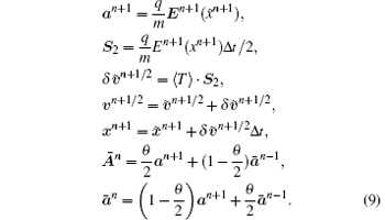
The particle movers and the MCC step can be parallelized easily. In our current version, the parallelized code is formed by a broadcast/reduce scheme.[24] That is, all of the processes share the field information and every process works on some particles. After the pushing step, every process weights its own particles and broadcast/reduce the ρ data of each other. Then the Poisson equation is solved serially and the solution is broadcast in the whole processes set. Finally, the final push and MCC step will be executed by processes on each of the owned particles. Anyway, the revising to put code to domain decomposition mode will not affect the movers and MCC procedures.
In the magnetized implicit electrostatic particle-in-cell algorithms, the Poisson equation (5) must be solved at every step. As the above description, the pushing step and MCC step are the same as the standard PIC scheme in essence. Then the only difference appears in the Poisson equation, discrete and solving.
Equation (5) can be discreted with the finite volume method. The integral form of the equation is

In a 1D uniform grid, the discrete form is very simple.[25] In this paper, we discuss the 2D r– z cylindrical system with Eϕ = Dϕ = 0 and Bϕ = 0. This is the most common case in discharging device simulation. Introduce the 

In this equation, the half-point value of the electric field and dielectric tensor must be made up. The half-point dielectric tensor can be made up by a simple arithmetic average. The half-point electric field needs to be calculated in two forms. First of all, the standard half integer point discrete scheme of potential gives out

Secondly, the Er in z direction half integer points and the Ez in r direction half integer points can be interpolated by the central difference of potential:


Put all the ansatz together, we can get a nine-point differential scheme:

where si, j to qi, j are nine coefficients and must be calculated at each step.
We should point out when the magnetic field is not very strong, one can apply five-term approximation as Welch’ s.[15] In this approximation, we can neglect the coefficients s, t, p, and q (anyway, the B field is still considered fully in the particle pusher). Then equation (11) can be solved by some convenient method.[26] The accuracy of this approximation should be checked carefully.
In the Descartes system or the 3D cases, the discrete can be done with similar steps.
Equation (11) is a linear equation system. In order to make effective and practical simulation for a real discharging system, the solver must have good efficiencies. In addition, the field solver is the major difficulty of parallelization. In the 1D case, the problem is a tridiagonal system and can be solved by a traditional TDMA.
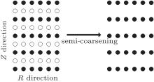
In the 2D case, the semi-coarsening multigrid method in Ref. [26] is generalized to solve the equations. This method can work robustly in both Descartes and cylindrical coordinate systems, even in the cases of Lz ≪ Lr or Lr ≪ Lz. Its major concepts can be understood by Fig. 1: Equation (11) can be written as Au = f, where the coefficient matrix A is the matrix formed by the coefficients in Eq. (11) and determined by 
init step:


Here the project operator 

At the solver initialization, the χ in every tier is calculated and the coefficients are made out with χ in every tier. Then the matrix A is assembled in all tiers. After the initialization, a MG(0, 1) cycle is executed to solve the linear system:
solving step:
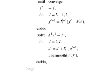
In this algorithm, linesmooth(ul, fl) is the line smooth procedure. It means that the equation AX = b is

Then the line smooth worked in r direction: for every i, solving the tridiagonal system
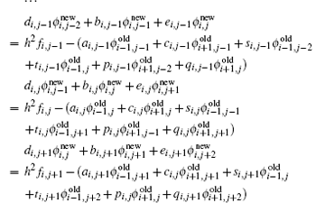
the i-th line smoothing is to solve the above equation set with i. The whole linesmooth procedure in one tier is to execute all of the N lines smoothing by the red– black order in this tier.
When χ is smooth and not very large, the solver converges after about 10– 30 iterations and works well for all grid sizes. If the χ becomes very large (say, max(χ ) > 1000), the solver could break down. Thus we use the solver only in the case of ω pΔ t < 20. We must claim that the solver can break down also while Ω becomes too large. Anyway, this problem will not occur in our all discharging simulations.
In the current version, this SMG solver is realized as a serial code, so that every computing node must broadcast and reduce the field information. Anyway, following the idea of pipeline algorithms in Ref. [24], this solver can be parallelized. This work is tedious but straightforward: i) split the simulating region to a series of bands: 0 < r < r1, r1 < r < r2, … and dispatch every band to nodes; ii) semi-coarsening the matrix in the z direction for each node synchronously; iii) run the linesmooth procedure. Because the procedure is a series of tri-diagonal system solving, it can be worked out by the pipeline parallel algorithm. We will use this algorithm for large device simulation or 3D simulation.
The MCC step is similar to our previous work.[27] In common cases, the electron versus background gas collision can be modeled by null collision methods. We use the MCC subroutine as previous works except that the particle recombine collisions. Because we do not use the particle sorting and the particle grouped by cell, the recombine procedure must be processed by some trick.
In the current version, the N-body (N > 1) collision is executed by cell probability accumulating. For example, the electron– ion recombinations are processed with the following steps: a) calculate the collision probability for all cells (i, j) and get the recombinated charge qc(i, j) in one step. b) All of the electrons execute a Monte Carlo recombination with a recombining charge data copy of qce = qc. If one electron in the (i, j) cell with charge qe < qce(i, j) are recombined, we can set qce(i, j) = qce(i, j) − qe. If the recombined electron charge qe > qce(i, j), we set qe = qe − qce(i, j) and qce(i, j) = 0. The electron macro-particle, which is recombined, is deleted from the particle lists and the neutral particle density in this cell is increased by the combined charge data. The running on particles is executed by a wheel-rolling order: the traversing of the particle running from k to N and then 1 to k, where k = rand(N) and N is the electron macro-particle numbers. c) All of the ions execute the recombination procedure with data copy qci = qc except the gas density increasing. The ionized exhausting of the gas is considered in a similar way.
Besides the N-body collision, the particle self-rezoning is considered. The three to two combinations and trivial splitting of macro-particles by Lapenta[28] are applied in our codes. There are two reasons to apply rezoning procedures. The first case is in the breakdown avalanche process, for example, which takes place in the pulsed ICP, where the electron charges increase 6– 8 orders and the combination procedure is applied to overcome the memory exhaust. The second case is in axi-symmetric simulating, the rezoning procedures are applied to control the noise. In the second case, when a macro-particle runs close to the axis, it can be split to several smaller macro-particles to decrease the stochastic noise. The split will cause the macro-particle numbers to increase continually, therefore we will combine very small macro-particles to control the particle number after some steps. We find the energy– momentum conservation is important in the rezoning, thus the three to two combination is applied.
Finally, the driving field ET should be calculated independently. In typical problems, the driving fields are inductive electric fields. If the plasma density is very low, we can ignore the plasma self-generated current. Then the inductive electric field can be solved by the applied external magnetic field. On the problems as ICP, the plasma skin effect must be considered. We solved these problems as Takekida did:[29] firstly, the inductive field and the plasma transverse in two dimensions can be written as harmonic form ET = Eθ exp{iω t}, jT = jθ exp{iω t} and the inductive field equation is

where ω is the RF driving frequency and Jext is the current density amplitude of the external coil. The plasma current density jθ is the average in one RF period:

Then equation (12) needs to be solved once per RF cycle.
We have used this algorithm to simulate the MTF pre-ionize procedure. In this device, a power inductive RF pulse applied on a cylinder gas tube with an external axis-direction magnetic field (biasing field) existing. In the pre-ionize stage, the plasma self-generated magnetic field can be ignored, then the electrostatic field plus the driving field model can be applied. The detailed discussion and the physical problem will be shown in another paper. Here we only describe the running features. The discharging cube is a cylinder column with gas filled. The driving field is an inductive field from a solenoid coil with sinusoidal current. The biasing field is a uniform axis-direction static magnetic field. At the beginning of the simulation, a seed plasma with density about 1014/m3 is put in the cube. When the driving field is applied, the discharge occurs.
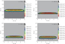
The simulation is executed with grid spacing DX ∼ 0.1 mm and 4– 8 CPU processes. Under our parameters, the breakdown takes place in dozens of nanoseconds. All the simulation worked on about 4 μ ms with several days. After about 100 ns, a torus profile plasma is built up and the maximum plasma densities become larger than 1019/m3. The typical discharge profiles are shown in Fig. 2.
When the discharge continues, the plasma generating exhausts the background gas and the plasma densities become the theoretical limit by gas densities. Before the gas is exhausted, the plasma electron temperature keeps in a low value (less than 10 eV). After the gas is exhausted, the electron and ion temperature increase rapidly. The biasing field and the gas pressure will modify the breakdown time and the plasma final parameters. In our cases, the quality behaviors of the discharging are all the same. In these parameters, the grid spacing is much larger than the Debye length but the simulating seems to be robust. We find the simulating results agree with the previous experiments[21] qualitatively well. We should point out that the five-term approximation gives out very close results with nine-term equation (11) in most of our cases.
In addition, we are running the magnetized CCP simulation with the present algorithm. It seems that the algorithm can be used to estimate the effects of magnetic field on CCP discharging. In our future study, we will apply the code on more problems, such as magnetized CCP, magnetized ICP, and others.
| 1 |
|
| 2 |
|
| 3 |
|
| 4 |
|
| 5 |
|
| 6 |
|
| 7 |
|
| 8 |
|
| 9 |
|
| 10 |
|
| 11 |
|
| 12 |
|
| 13 |
|
| 14 |
|
| 15 |
|
| 16 |
|
| 17 |
|
| 18 |
|
| 19 |
|
| 20 |
|
| 21 |
|
| 22 |
|
| 23 |
|
| 24 |
|
| 25 |
|
| 26 |
|
| 27 |
|
| 28 |
|
| 29 |
|


