Ramsey-CPT spectrum with the Faraday effect and its application to atomic clocks*
[Tian Yuana) , Tan Bo-Zhongc) , Yang Jingb) , Zhang Yib) , Gu Si-Honga), b), c)†  ]
]
]
|
|


†Corresponding author. E-mail: shgu@wipm.ac.cn
*Project supported by the National Natural Science Foundation of China (Grant Nos. 11304362 and 11204351).
A method that obtains the Ramsey-coherent population trapping (CPT) spectrum with the Faraday effect is investigated. An experiment is implemented to detect the light polarization components generated from the Faraday effect. The experimental results agree with the theoretical calculations based on the Liouville equation. By comparing with the method without using the Faraday effect, the potential of this method for a CPT-based atomic clock is assessed. The results indicate that this method should improve the short-term frequency stability by several times.
The scheme popularly employed for coherent population trapping (CPT) atomic clocks uses the vertical-cavity surface-emitting laser (VCSEL) to provide lasing.[1] The VCSEL excited with microwave-modulated current emits a multichromatic laser beam, where the ± 1 sidebands are used to interact with the ensemble of atoms. The linearly polarized laser field of the VCSEL output is converted to a circularly polarized one by a quarter-wave plate, which is then used to prepare the atoms in the CPT state. The CPT signal is extracted from the transmission light after the multichromatic light interacts with the atoms. This scheme has a simple structure and is widely applied in the physics package of miniature CPT atomic clocks and chip-scale atomic clocks.[2] However, this scheme has three main shortcomings: (i) the non-coupled Zeeman end-states, via which the circularly polarized laser field interacts with atoms, results in low atom use, (ii) sidebands besides the ± 1 sidebands add shot noise, and (iii) the laser beam emitted from the VCSEL with a 100-MHz linewidth causes strong FM– AM conversion and AM noises.[3]
To overcome the limitations of this popular scheme, many improved schemes have been proposed. Push-pull optical pumping, [4, 5]σ + – σ − , [6, 7] lin⊥ lin, [8] four-wave mixing, [9] lin∥ lin, [10, 11] and quasi-bichromatic lin⊥ lin[12] can eliminate the end-state atoms. The polarization-selective method only detect the ± 1 sidebands so the noise caused by the other sidebands can be removed.[13, 14] A differential detection method reduces the FM– AM noise by a factor of 10.[15] In addition, the combination of CPT resonance and Ramsey interference, which produces the Ramsey-CPT fringes with narrower linewidths as a frequency discriminating signal over the traditional CPT signal, is also a promising route towards realizing a more accurate CPT atomic clock.[16, 17]
Our group has performed related experiments, such as lin∥ lin CPT, [18] multipulse Ramsey-CPT, [19] and more recently, a frequency-switching scheme for a packaged Ramsey-CPT atomic clock, defined as the non-Faraday– Ramsey-CPT (NFRC) scheme.[20] Inspired by our previous research, we now propose a method using the Faraday effect to obtain a Ramsey-CPT spectrum, called the Faraday– Ramsey-CPT (FRC) scheme, and discuss its potential for a packaged atomic clock. The findings are presented below.
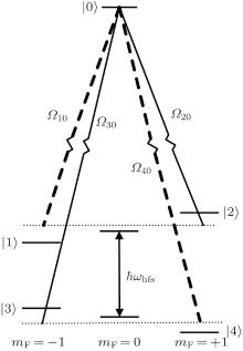
As shown in Fig. 1, a linearly polarized bichromatic laser field with angular frequency ω 1 and ω 2 interacts with alkali-metal atoms in the presence of a magnetic field B. The laser field is equivalent to the superposition of right-handed (σ + ) and left-handed (σ − ) circularly polarized laser fields. Two Λ -type CPT resonances occur and are marked as solid and dashed lines, respectively. The calculation is based on the Liouville equation with a phenomenological term for spontaneous decay ℜ ρ :

For the Λ -type CPT resonance configuration (dashed line of Fig. 1), the Hamiltonian can be expressed as

where Δ + = ω 1 − ω 2 − (ω hfs − ω B) = Δ + ω B. Here, Δ and Δ + are the Raman detuning angular frequencies for B = 0 and B ≠ 0, respectively, and ω B denotes the variation of the angular frequency difference between the two hyperfine levels of the ground state due to the magnetic field B.
 | Fig. 1. Scheme depicting the interaction between the lin∥ lin field and alkali-metal atoms. |
Ramsey-CPT interference can be generated from two processes by which a bichromatic laser field interacts with the atoms which evolve freely when the laser field disappears. When the atoms evolve freely, Ω ij = 0, reducing the above Hamiltonian to

.
We assume that the Rabi frequencies of Eq. (2) obey Ω 10 = Ω 20 = − Ω 30 = Ω 40 = Ω . The minus sign appears in − Ω 30 because the transition phase of | 3〉 → | 0〉 is opposite to that of | 4〉 → | 0〉 . After the system undergoes interaction of the laser field and the atoms, free evolution of the atoms, and a further interaction, we take the time Δ t and use Eqs. (2) and (3) to solve Eq. (1) to obtain the mean of ρ 10 and ρ 40. To the first-order approximation, we have

where ξ (Δ + ) is the dispersion generated by the CPT resonance corresponding to the dashed line of Fig. 1 when B ≠ 0, γ is the relaxation rate of the coherence between the ground state hyperfine levels, T is the free evolution time, Ω p is the effective optical Rabi frequency given by Ω p = Ω 2/Γ with Γ the relaxation rate of the population from the excited state to the ground state.
Similarly, for the CPT resonance (solid line in Fig. 1), we obtain

where Δ − = ω 1 − ω 2 − (ω hfs + ω B) = Δ − ω B. ξ (Δ − ) is the dispersion generated by the CPT resonance corresponding to the solid line of Fig. 1 when B ≠ 0.
In both Eqs. (4) and (5), we have

The polarization of the laser field will be rotated due to the Faraday effect when it interacts with atoms when B ≠ 0.[21– 23] We define the light components in the vertical direction of the original polarization of the laser field as the vertical components. The intensity of the vertical components is derived as
where i is 1 or 2, Ei and ki denote the electric field and wave vector of ω i, respectively, 

When the intensity of the laser field is weak and B is small, 
where N is the atomic density.
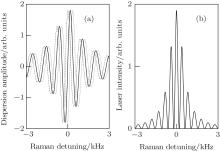
Figures 2(a) and 2(b) is based on Eqs. (6) and (8), respectively. According to Eq. (6), the dispersions of σ ± are identical when B = 0 and the Ramsey-CPT spectrum corresponding to ξ (Δ ) is depicted as the solid line in Fig. 2(a). When B increases, the Zeeman splitting of the ground state levels of alkali-metal atoms shifts the Ramsey-CPT spectra corresponding to ξ (Δ + ) and ξ (Δ − ) in opposite directions. The Ramsey-CPT spectrum corresponding to 

 | Fig. 2. (a) Dispersions of the two CPT resonances when B = 0 and B = 6 μ T. The solid line represents ξ (Δ ) when B = 0, the dashed line represents ξ (Δ + ) when B = 6 μ T, and the dotted line represents ξ (Δ − ) when B = 6 μ T. (b) Ramsey-CPT spectrum corresponding to  |
We performed an experimental study on the Ramsey-CPT spectrum corresponding to 
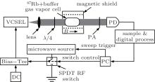
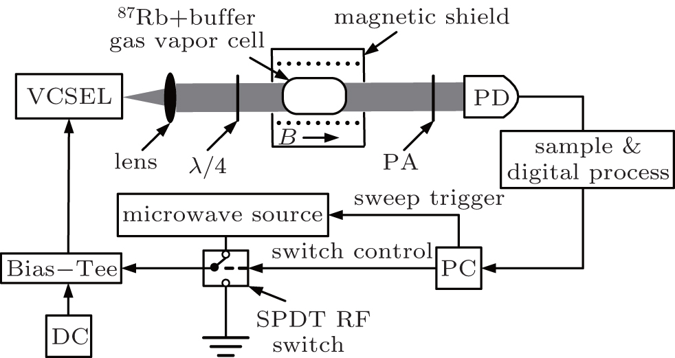 | Fig. 3. Schematic diagram of the experimental setup. λ /4: quarter-wave plate, PD: photo detector, DC: direct current, PA: polarization analyzer, B: applied magnetic field. |
With the setup of the FRC scheme, the orientation of the quarter-wave plate (λ /4) axis is parallel to the laser-field polarization and crossed with respect to the polarization analyzer (PA), which is placed on a guide rail before the photo detector (PD). Therefore, a lin∥ lin field is incident on the vapor cell and the PD only detects the vertical components through the PA. To compare with the NFRC scheme, the axis of λ /4 is adjusted to convert the polarization of the beam from linear to circular and the PA is removed from the guide rail, so the setup reverts to that of Ref. [20]. The Ramsey-CPT spectra from the FRC and NFRC schemes are recorded with the same experimental parameters.
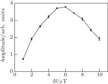
We calculated an optimum B using Eq. (8) and experimentally measured the amplitude of the central fringe of the Ramsey-CPT spectrum corresponding to 

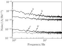
We also measured the noise density of the two Ramsey-CPT spectra. Because the data sampling frequency is nearly 82 Hz, the effective Fourier frequency range is less than 41 Hz. We stabilized the microwave frequency to the value corresponding to the peak of the central Ramsey-CPT fringe (Fig. 5) and recorded the photoelectric signals (Fig. 6); curves a and b′ show the noise density calculated from the signals. As only the vertical components are detected for the FRC scheme, the amplitude of the central Ramsey-CPT fringe is decreased to 1/25 that for the NFRC scheme. To compare the SNRs for the two schemes, we multiplied the recorded data from the FRC scheme by a factor of 25. The curve b of Fig. 6 shows the noise density after amplification. The SNR for the FRC scheme has improved three-fold over that for the NFRC scheme (curve a and b of Fig. 6). The curve c of Fig. 6 shows the noise density of the PD.
 | Fig. 4. Amplitude of the central fringe as a function of B. The total incident intensity is 1.6 mW/cm2. |
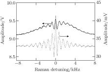
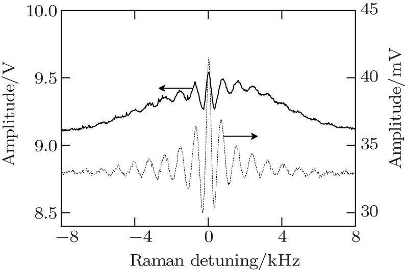 | Fig. 5. Ramsey-CPT spectra obtained from the FRC (dashed line) and NFRC (solid line) schemes. The total incident intensity is 1.6 mW/cm2 and B = 6 μ T. There is a 10-fold variation between the ratios of amplitude of the central Ramsey-CPT fringe to background for the two schemes. |
 | Fig. 6. Amplitude noise under different conditions. Curve a for NFRC scheme, b for FRC scheme after amplification. b′ for FRC scheme, and c for no light being incident on PD. |
The motivation in studying Ramsey-CPT interference for the FRC scheme is to seek a better scheme for a packaged CPT-based atomic clock. The SNR is improved with the Faraday effect and B set to nearly 6 μ T, which falls within the ideal range from 5 μ T to 10 μ T for the magnetic field in the popular CPT scheme. Therefore, the proposed FRC scheme is suitable.
The NFRC scheme uses the VCSEL as laser source, as for the popular CPT scheme. It has the advantage of small volume and lower power consumption. However, the fluctuations of the output light power cause the AM noise. In addition, the laser spectrum of the VCSEL is wide. Furthermore, the popular CPT scheme adopts the Doppler absorption line to stabilize the laser frequency. With these features, small variations in laser frequency cause amplitude fluctuations in the detected signal that induce strong FM– AM noise.
From Fig. 5, most of the optical signal for the FRC scheme is blocked by the PA, which includes the multichromatic laser field other than the ± 1 sidebands. Therefore, the AM and shot noises are reduced greatly. Moreover, only a few of the Doppler absorption signal are detected due to the vertical components detection that results in the suppression of the FM– AM noise. The self-noise of the PD could not be reduced and has a large proportion from curves b′ and c of Fig. 6.
To discuss differences in the short-term stability between the two schemes, we use the following general expression for noise, [24, 25]

where S/N is the SNR, measured in a 1-Hz bandwidth at the modulation frequency, and Q the resonance quality factor given by Q = ω hfs/(2 π Δ ν ) with Δ ν the signal linewidth.
From Fig. 5, the linewidths of the central Ramsey-CPT fringes for the two schemes are nearly the same. In practice, the short-term stability is measured after the microwave frequency is stabilized. From Fig. 6, the FRC scheme has the potential to improve the short-term stability by several times when the modulation frequency is half of the data sampling frequency.
We proposed a scheme that uses the Faraday effect to obtain the Ramsey-CPT interference spectrum. By solving the Liouville equation, we derived an expression for the interference spectrum and studied its characteristics. From the calculations, the spectrum is generated from the dispersion signals caused by the interaction between laser field and atoms for B ≠ 0, which varies with B. We chose appropriate field strength to obtain a high SNR spectrum.
We performed an experiment to verify the theory. Experimental and theoretical results were in agreement basically. We also performed a comparative experiment for the FRC and NFRC schemes. Through the reduction of the AM, shot, and FM– AM noises in the detected signal, the FRC scheme could be employed to build an atomic clock with short-term stability several times better than that for the NFRC scheme.
Compared with the popular packaged CPT-based atomic clock, the electronics of the NFRC scheme includes a microwave switch[20] whereas the FRC scheme includes a PA in the physics package again. The FRC scheme still has a similar volume and power consumption as that for the popular scheme despite the addition of two devices. The short-term stability for the NFRC-scheme atomic clock has been increased significantly with the FRC scheme having further potential to improve short-term stability by several times. Therefore, the FRC scheme can be seen as preferable in a high-performance compact atomic clock based on CPT.
| 1 |
|
| 2 |
|
| 3 |
|
| 4 |
|
| 5 |
|
| 6 |
|
| 7 |
|
| 8 |
|
| 9 |
|
| 10 |
|
| 11 |
|
| 12 |
|
| 13 |
|
| 14 |
|
| 15 |
|
| 16 |
|
| 17 |
|
| 18 |
|
| 19 |
|
| 20 |
|
| 21 |
|
| 22 |
|
| 23 |
|
| 24 |
|
| 25 |
|