Miao Yan-Qin, Gao Zhi-Xiang, Zhang Ai-Qin, Li Yuan-Hao, Wang Hua, Jia Hu-Sheng, Liu Xu-Guang, Tsuboi Taijuf. High color rendering index white organic light-emitting diode using levofloxacin as blue emitter* . Chinese Physics B, 2015, 24(5): 057802
Permissions
High color rendering index white organic light-emitting diode using levofloxacin as blue emitter*
Miao Yan-Qina),c), Gao Zhi-Xiangb), Zhang Ai-Qina),c), Li Yuan-Haoa),c), Wang Huaa),c)†, Jia Hu-Shenga),d)‡, Liu Xu-Guanga),e), Tsuboi Taijuff)
Key Laboratory of Interface Science and Engineering in Advanced Materials, Taiyuan University of Technology, Ministry of Education, Taiyuan 030024, China
School of Physical Science and Electronics, Shanxi Datong University, Datong 037009, China
Research Center of Advanced Materials Science and Technology, Taiyuan University of Technology, Taiyuan 030024, China
College of Materials Science and Engineering, Taiyuan University of Technology, Taiyuan 030024, China
College of Chemistry and Chemical Engineering, Taiyuan University of Technology, Taiyuan 030024, China
Institute of Advanced Materials, Nanjing University of Technology, Nanjing 210009, China
*Project supported by the Program for New Century Excellent Talents in University of Ministry of Education of China (Grant No. NCET-13-0927), the International Science & Technology Cooperation Program of China (Grant No. 2012DFR50460), the National Natural Science Foundation of China (Grant Nos. 21101111 and 61274056), and the Shanxi Provincial Key Innovative Research Team in Science and Technology, China (Grant No. 2012041011).
Abstract
Levofloxacin (LOFX), which is well-known as an antibiotic medicament, was shown to be useful as a 452-nm blue emitter for white organic light-emitting diodes (OLEDs). In this paper, the fabricated white OLED contains a 452-nm blue emitting layer (thickness of 30 nm) with 1 wt% LOFX doped in CBP (4,4’-bis(carbazol-9-yl)biphenyl) host and a 584-nm orange emitting layer (thickness of 10 nm) with 0.8 wt% DCJTB (4-(dicyanomethylene)-2- tert-butyl-6-(1,1,7,7-tetramethyljulolidin-4-yl-vinyl)-4H-pyran) doped in CBP, which are separated by a 20-nm-thick buffer layer of TPBi (2,2’,2”-(benzene-1,3,5-triyl)-tri(1-phenyl-1H-benzimidazole). A high color rendering index (CRI) of 84.5 and CIE chromaticity coordinates of (0.33, 0.32), which is close to ideal white emission CIE (0.333, 0.333), are obtained at a bias voltage of 14 V. Taking into account that LOFX is less expensive and the synthesis and purification technologies of LOFX are mature, these results indicate that blue fluorescence emitting LOFX is useful for applications to white OLEDs although the maximum current efficiency and luminance are not high. The present paper is expected to become a milestone to using medical drug materials for OLEDs.
Keyword:
78.60.Fi; 72.80.Le; levofloxacin; blue organic light emitting diodes; white organic light-emitting diodes; high color rendering index
White organic light-emitting diodes (WOLEDs) have attracted considerable attention in the past few decades owing to their potential applications in solid-state lighting sources and the next-generation full-color flat panel displays with low energy consumption, light weight, flexibility, and super-thin feature.[1– 7] To obtain high electroluminescence (EL) efficiency, phosphorescence materials have been widely used in WOLEDs because of the higher internal quantum efficiency of 100% than that (25%) of fluorescent materials.[8– 10] The phosphorescent materials, however, have a disadvantage of EL quenching as a result of triplet– triplet annihilation (TTA) at high current densities, i.e., roll-off.[11] Another serious disadvantage is that they are expensive because of the high cost of transition metal salts (e.g., Ir(Cl)3) involved in synthesis of phosphorescence material, such as blue-emitting material bis(3, 5-difluoro-2-(2-pyridyl)phenyl-(2-carboxypyridyl)iridium(III) (FIrpic) and green-emitting material fac-tris(2-phenylpyridine)iridium(III) (Ir(ppy)3).
Less-expensive materials with a lower synthesis cost are preferable for the OLED panel companies even if the efficiency is not so high as that of phosphors. In this point of view, the fluorescent materials become a candidate of the emitting materials.[12]
Levofloxacin C18H20FN3O4((S)-9-fluoro-2, 3-dihydro-3-methyl-10-(4-methylpiperazin-1-yl)-7-oxo-7H-pyrido[1, 2, 3-de]-1, 4-benzoxazine-6-carboxylic acid, abbrevrated as LOFX hereafter) is an antibiotic medicament that is used for treating bacterial infections of the sinuses, skin, lungs, ears, bones, and joints caused by susceptible bacteria.[13– 17] A blue emission has been reported for LOFX.[18, 19] We have noted that the synthesis and purification technologies of LOFX are mature, inducing cheaper price (about 17 US dollars per gram) than those of most existing blue fluorescent OLED materials (about 190 US dollars per gram).
In our previous work, we demonstrated that LOFX has the HOMO and LUMO energies of − 6.2 eV and − 3.2 eV, respectively, and high molecule decomposition temperature (Td) of 327 ° C, which is suitable for OLED materials.[19]
In this paper, we use LOFX as the blue emitting material for WOLEDs when LOFX is combined with the emitting layer (EML) of orange emitting compound, 4-(dicyanomethylene)-2-tert-butyl-, 6, -(1, 1, 7, 7-tetra-methyljulolidin-4-yl-vinyl)-, 4H, -pyran (DCJTB). A high color rendering index (CRI) of 84.5 and the Commission Internationale de L’ Eclairage (CIE) chromaticity coordinates of (0.33, 0.32) are obtained.
2. Experimental details
The OLEDs with the emission area of 3× 3 mm2 were fabricated on the pre-patterned indium tin oxide (ITO) glass substrate with a sheet resistance of 15 Ω /□ . ITO substrates as the anode were cleaned by ultra-sonication in baths of detergent water, deionized water, and acetone for 15 min each, blown with dry nitrogen, and then treated with UV ozone for 8 min. After these processes, the substrates were transferred into a vacuum chamber for sequential deposition of all organic functional layers by thermal evaporation below a vacuum of 5 × 10− 4 Pa. The deposition rates for organic materials, LiF and Al were about 1 Å /s, 0.1 Å /s, and 10 Å /s, respectively. The device performances of OLEDs were characterized by a Keithley 2400 source meter combined with a Photo Research PR 655 spectrometer. All measurements were performed at room temperature in ambient atmosphere without device encapsulation.
The molecule structures of the organic materials used in this paper are shown in Fig. 1. The compounds N, N′ -bis(naphthalen-1-yl)-N, N′ -bis (phenyl)-benzidine (NPB), 4, 4’ -bis(carbazol-9-yl) biphenyl (CBP), 4, 7-diphenyl-1, 10-phenanthroline (Bphen), and 2, 2’ , 2” -(benzene-1, 3, 5-triyl)-tri(1-phenyl-1H-benzimidazole (TPBi) were used as the hole-transporting layer (HTL), the electron-blocking layer (EBL), the electron-transport layer (ETL), and the buffer layer, respectively.
Fig. 1. The chemical structures of organic materials used in this paper.
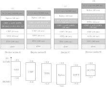
Four kinds of OLEDs were fabricated, which are denoted Device series-A, Device series-B, Device C, and Device series-D. These devices have the following layer structures.
Device series-A ITO/NPB/CBP/CBP: x wt%LOFX (30 nm)/Bphen(40 nm)/LiF/Al, where the concentration (in x wt%) of LOFX was variously changed as 0.5, 0.8, 1.0, and 2.0 wt%. The parenthesis indicates the layer thickness. This series of OLEDs were fabricated to find the best concentration of LOFX doped in the CBP host, which gives a high EL performance from the blue OLEDs with a LOFX emitter.
Device series-B ITO/NPB/CBP/CBP: y wt%DCJTB (30 nm)/Bphen(40 nm)/LiF/Al, where the concentration (in y wt%) of DCJTB was variously changed as 6, 4, 3, 1, and 0.8 wt%. This series of OLEDs were fabricated to find the best concentration of DCJTB doped in the CBP host, which gives the color suitable to obtain white emission by the combination of blue emission from LOFX.
Device C ITO/NPB/CBP/CBP: 1 wt%LOFX(30 nm)/CBP: 0.8 wt%DCJTB(30 nm)/Bphen(40 nm)/LiF/Al. This device was fabricated to check the generation of white light.
Device series-D ITO/NPB/CBP/CBP: 1 wt%LOFX (30 nm)/TPBi(20 nm)/CBP: 0.8 wt%DCJTB (z nm)/Bphen (40 nm)/LiF/Al, where the thickness (in z nm) of EML with DCJTB was variously changed as 30 nm, 20 nm, and 10 nm. This series of OLEDs were fabricated to find the best thickness of EML with a DCJTB emitter, which gives high EL performance as WOLEDs.
The thicknesses of NPB, CBP, LiF, and Al layers used as HTL, EBL, the electron injection layer, and the cathode were fixed to be 40 nm, 10 nm, 1 nm, and 200 nm, respectively, in all the devices.
The device structures are shown in Fig. 2, together with the highest occupied molecular orbital (HOMO) and the lowest unoccupied molecular orbital (LUMO) energy levels of organic molecules used in the present work.
Fig. 2. Schematic device structures of Devices series-A (a), Device series-B (b), Device C (c), and Device series-D (d), together with the HOMO and LUMO energy levels of organic molecules (e).
3. Results and discussion
3.1. The blue OLEDs with a LOFX emitter
Figure 3(a) shows the EL spectra of Device series-A (x = 1.0) at various bias voltages. An EL band with maximum wavelength at 452 nm due to LOFX is observed, which shows no peak shift by changing the bias voltage. Figure 3(b) shows the luminance– voltage (L– V) characteristics of Device series-A with 0.5, 0.8, 1.0, and 2.0 wt% LOFX doped in the CBP host. Among them, the Device series-A (x = 1.0) expresses the lowest turn-on voltage of 4.5 V (which gives rise to a luminance of 1 cd/m2) and the biggest luminance of 2315 cd/m2. Based on these results, we chose 1.0 wt% as the optimized concentration of LOFX in OLEDs with a blue EML of LOFX hereafter.
Fig. 3. (a) EL spectra of Device series-A (x = 1.0) at various voltages; (b) the luminance– voltage (L– V) characteristics of the Devices series-A.
3.2. The orange OLEDs with a DCJTB emitter
To obtain white light emission, the OLED with complementary color EMLs is considered to be one of the most effective methods.[20– 25] In this paper, we also fabricated a WOLED with double EMLs. A complementary color of a blue-light that is located at 452 nm is an orange light with an emission peak at around 580 nm. Here, the blue EML is formed by doping LOFX in CBP, the orange EML is formed by doping DCJTB in CBP. First, the concentration of DCJTB from Device series-B with the single orange EML is optimized.
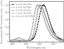
Figure 4 shows the EL spectra of Device series-B with various concentrations of DCJTB doped in the CBP host. With increasing concentration of DCJTB from 0.8 wt% to 6 wt%, the EL band attributed to DCJTB shows an obvious red-shift from 584 nm to 632 nm. Among the EL peaks, the emission peak at 584 nm meets the requirement of being a complementary color to the 452 nm blue-light emission of LOFX.[26, 27] Therefore, the concentration of 0.8 wt% is selected as the optimum concentration of DCJTB doped in CBP hereafter. Compared with other Device series-B, the Device series-B (y = 0.8) exhibits the lowest turn-on voltage of 4.3 V and the highest maximum current efficiency of 4.36 cd/A. Hence, it is confirmed that optimized concentration of DCJTB doped in CBP is 0.8 wt%.
Fig. 4. The normalized EL spectra of Devices series-B with different concentrations of DCJTB doped in CBP.
It has been identified that solvatochromism of fluorescence material is due to the variation in dipole moment of fluorescence molecules by their interaction in a polarizable environment. The red-shift of the EL band of the fluorescence dopant with increasing doping concentration has also been observed in organic thin films, due to the solid-state solvation effect.[28] Hence, the similar red-shift in the EL spectra of Fig. 4 is attributed to solid-state solvation effect.
As shown in Fig. 4, an additional weak EL band is also observed at about 450 nm in the EL spectrum of Device series-B with an EML of 0.8 wt% DCJTB, which is close to the EL band corresponding to the emission of NPB.[29] This indicates that excitons diffuse from EML to HTL of NPB, which occurs not in highly doped EML (e.g., 6 wt%) but in lightly doped EML (e.g., 0.8 wt%). In EML of Device series-B, electrons injected into LUMO of CBP combine with holes injected into HOMO of CBP to form excitons, which excite DCJTB to emit orange light by Fö rster energy transfer from CBP to DCJTB.[30, 31] In addition, the quantities of excitons consumed in excitation of DCJTB are determined by the doping concentration of DCJTB. Hence, nearly all excitons deactivate by exciting DCJTB to emit orange light in the highly doped EML, inducing the absence of EL band at 450 nm. Most of excitons deactivate by exciting DCJTB to emit orange light in the lightly doped EML, and a small part of excitons diffuse to HTL of NPB, inducing the weak EL band at 450 nm corresponding to NPB.
3.3. The WOLEDs with two EMLs
As mentioned above, the exciton diffusion from EML to HTL occurs in the Device series-B (y = 0.8). For effective utilization of diffused excitons, a blue EML of LOFX is inserted between the orange EML of DCJTB and HTL, denoted as Device C.
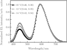
Figure 5 shows the EL spectra of Device C under different bias voltages. The EL spectra consist of double EL peaks at 452 and 584 nm, corresponding to emissions of LOFX and DCJTB, respectively. The EL intensity of LOFX is weaker than that of DCJTB, although the ratio of the former intensity to the latter one increases with increasing voltage (Fig. 6). We measured the fluorescence quantum yield of the solid powders of LOFX and DCJTB using a FluoroMax-4 fluorescence spectrophotometer attached with an integrating sphere. LOFX exhibits a smaller fluorescence quantum yield of 5.54% than that of DCJTB (14.70%), which is one reason for the smaller EL intensity of LOFX than that of DCJTB. In addition, another reason is unbalanced charge mobilities of NPB and Bphen used as HTL and ETL, respectively. The hole mobility of NPB is 4.0 × 10− 4 cm2· V− 1· s− 1, [32] which is higher than the electron mobility of Bphen (2.0 × 10− 5 cm2· V− 1· s− 1).[33] In this case, the hole– electron recombination zone locates in the EML of DCJTB:CBP, resulting in stronger EL intensity of DCJTB compared with that of LOFX.
Fig. 6. The intensity ratio of the 452-nm blue-light EL to the 584-nm orange-light EL, Iblue/Iorange, plotted against bias voltage.
Smaller blue EL intensity of LOFX than orange EL intensity of DCJTB never leads to white light, as seen from the CIE coordinates (0.42, 0.34) at 14 V (Fig. 5), which are largely deviated from the white CIE point (0.333, 0.333). Hence, it is necessary to match charge transfer in double EMLs in Device C for realization of pure white light emission. To gain this aim, a buffer layer of TPBi is introduced between the orange EML of CBP:DCJTB and the blue EML of CBP:LOFX, denoted as Device series-D.
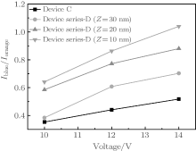
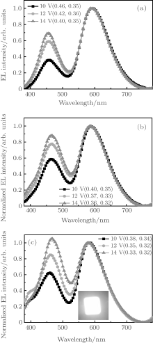
Figures 7(a)– 7(c) show the EL spectra of Device series-D with the CBP:DCJTB layer thicknesses of 30, 20, and 10 nm at different voltages, respectively. Similar with the case of Device C, the intensity ratio of LOFX emission to DCJTB emission increases with increasing voltage (Fig. 6). In organic materials, electron mobility and hole mobility vary with increasing electric field and electron mobility rises that are faster than its hole mobility.[34, 35] As a result, the hole– electron recombination zone shifts from orange EML to blue EML with increasing bias voltage, [36– 38] leading to the increase in the EL intensity ratio of blue-emitting LOFX to orange-emitting DCJTB with increasing of the bias voltage.
Fig. 7. The normalized EL spectra of Devices series-D at different bias voltages: (a) Device series-D (z = 30); (b) Device series-D (z = 20); (c) Device series-D (z = 10). CIE coordinates are also indicated. Inset in panel (c) is the photo of Device D (z = 10) at 14 V.
In Device series-D, the energy gap between HOMO levels of CBP and TPBi is 0.3 eV (Fig. 2). This suggests that the holes transferred from the EML of CBP:LOFX are partially blocked by the buffer layer of TPBi, and the holes transferred into the EML of CBP:DCJTB are reduced. As a result, distinguished with Device C, the electron– hole recombination zone is broadened from the EML of CBP:DCJTB to the EML of CBP:LOFX.[39] Therefore, the reverse of the intensity ratio of blue LOFX emission to orange DCJTB emission becomes possible, leading to white light emission of Device series-D. The highest blue EL intensity of LOFX is obtained in Device series-D (z = 10), resulting in the CIE coordinates at 14 V of (0.33, 0.32) and the higher color rendering index (CRI) of 84.5. These EL characteristics indicate that the LOFX emitter can be used in WOLEDs by combining with the DCJTB emitter.
However, an obvious emission peak at above 400 nm can be observed in the EL spectra of Device series-D (z = 10) with respect to Device series-D (z = 20) and Device series-D (z = 30), which should originate from the emission of the 10-nm CBP layer. As the thickness of the orange EML reduces from 30 nm, to 20 nm, and then to 10 nm, the recombination zone of corresponding devices shifts from orange EML to blue EML. When the thickness of orange EML is 10 nm, the recombination zone simultaneously covers an orange EML, a blue EML, and a part CBP layer, inducing a peak of 400 nm from CBP in the EL spectra of Device series-D (z = 10).
Figure 8 shows the current density dependence of the current efficiency and luminance of Device series-D (z = 10), which exhibites the maximum current efficiency of 1.79 cd/A under a current density of 17.7 mA/cm2, the luminance of 3869 cd/m2 under a current density of 217 mA/cm2. In Device series-D (z = 20), a higher maximum current efficiency of 2.37 cd/A at bias voltage of 14 V and a higher luminance of 3990 cd/m2 under a current density of 217 mA/cm2 are obtained. Nevertheless, its CIE coordinates of the (0.36, 0.32) deviate slightly from a pure white light point, which are not as good as those of Device series-D (z = 10). Taking into account that LOFX is less expensive and the synthesis and purification technologies of LOFX are mature, it is suggested that LOFX is useful for future applications in WOLEDs although the maximum current efficiency and luminance are not so high.
Fig. 8. The current efficiency-current density-luminance characteristics of Device series-D (z = 10).
4. Conclusions
Levofloxacin (LOFX), which is well known as an antibiotic medicament, is shown to be useful as a 452-nm blue emitter for white organic light-emitting diodes (WOLEDs). To find the best concentration of LOFX doped in CBP host, EL performance of blue OLEDs with various concentrations of LOFX is investigated. A concentration of 1 wt% LOFX is found to give low voltage EL operation. To find the best concentration of DCJTB doped in a CBP host, which gives the color suitable to obtain white emission by a combination of blue emission from LOFX. EL performance of orange OLEDs with various concentrations of DCJTB is investigated. A concentration of 0.8 wt% DCJTB is found to give an EL band with maximum at 584 nm, which is suitable as one of the complementary colors for the 452-nm emission of LOFX. To obtain white light from OLEDs, a 20-nm thick buffer layer of TPBi is inserted between the 452-nm blue emitting layer (thickness of 30 nm) with 1 wt% LOFX doped in CBP host and the 584-nm orange emitting layer (thickness of 10 nm) with 0.8 wt% DCJTB doped in CBP. High CRI of 84.5 and CIE chromaticity coordinates of (0.33, 0.32), which is close to ideal white emission CIE (0.333, 0.333), are obtained at a bias voltage of 14 V. Therefore, taking into account that LOFX is less expensive and the synthesis and purification technologies of LOFX are mature, it is suggested that blue fluorescence emitting LOFX is useful for applications to white OLEDs although the maximum current efficiency and luminance still need to be further improved.
LiL, WinckelS V, GenoeJ and HeremansP2009Appl. Phys. Lett. 95153301DOI:10.1063/1.3246160[Cited within:1][JCR: 3.794]
36
WallaceJ U, YoungR H, TangC W and ChenS H2007Appl. Phys. Lett. 91152104DOI:10.1063/1.2798592[Cited within:1][JCR: 3.794]
37
KhademiS, SongJ Y, WyattP B, KreouzisT and GillinW P2012Adv. Mater. 242278DOI:10.1002/adma.201103830[Cited within:1][JCR: 14.829]
38
ShenY, KleinM W, JacobsD B, ScottJ C and MalliarasG G2001Phys. Rev. Lett. 863867DOI:10.1103/PhysRevLett.86.3867[Cited within:1][JCR: 7.943]
39
JouJ H, ShenS M, LinC R, WangY S, ChouY C, ChenS Z and JouY C2011Org. Electron. 12865DOI:10.1016/j.orgel.2011.02.012[Cited within:1][JCR: 3.836]
1
2004
14.829
0.0
... [1#cod#x2013 ...
1
2006
38.597
0.0
1
2010
14.829
0.0
1
2008
14.829
0.0
1
2012
3.794
0.0
1
2014
1.148
1.2429
1
2013
0.0
0.0
... 7] To obtain high electroluminescence (EL) efficiency, phosphorescence materials have been widely used in WOLEDs because of the higher internal quantum efficiency of 100% than that (25%) of fluorescent materials ...
1
2008
14.829
0.0
... [8#cod#x2013 ...
1
2011
14.829
0.0
1
2012
5.968
0.0
... 10] The phosphorescent materials, however, have a disadvantage of EL quenching as a result of triplet#cod#x2013 ...
1
2010
3.836
0.0
... [11] Another serious disadvantage is that they are expensive because of the high cost of transition metal salts (e ...
1
2011
3.836
0.0
... [12] ...
1
2007
9.374
0.0
... [13#cod#x2013 ...
1
2007
9.374
0.0
1
2010
9.374
0.0
1
2013
0.0
0.0
1
2012
2.379
0.0
... 17] A blue emission has been reported for LOFX ...
1
2008
0.644
0.0
... [18,19] We have noted that the synthesis and purification technologies of LOFX are mature, inducing cheaper price (about 17 US dollars per gram) than those of most existing blue fluorescent OLED materials (about 190 US dollars per gram) ...
2
2012
0.0
0.0
... [18,19] We have noted that the synthesis and purification technologies of LOFX are mature, inducing cheaper price (about 17 US dollars per gram) than those of most existing blue fluorescent OLED materials (about 190 US dollars per gram) ...
... [19] ...
1
2002
3.794
0.0
... [20#cod#x2013 ...
1
2006
3.794
0.0
1
2007
3.794
0.0
1
2008
1.148
1.2429
1
2008
0.811
0.4541
1
2008
1.148
1.2429
... 25] In this paper, we also fabricated a WOLED with double EMLs ...
1
2009
14.829
0.0
... [26,27] Therefore, the concentration of 0 ...
1
2006
3.794
0.0
... [26,27] Therefore, the concentration of 0 ...
1
1999
2.145
0.0
... [28] Hence, the similar red-shift in the EL spectra of Fig ...
1
2001
2.528
0.0
... [29] This indicates that excitons diffuse from EML to HTL of NPB, which occurs not in highly doped EML (e ...
1
2004
0.0
0.0
... [30,31] In addition, the quantities of excitons consumed in excitation of DCJTB are determined by the doping concentration of DCJTB ...
1
2009
9.765
0.0
... [30,31] In addition, the quantities of excitons consumed in excitation of DCJTB are determined by the doping concentration of DCJTB ...
1
2013
3.794
0.0
... 1,[32] which is higher than the electron mobility of Bphen (2 ...
1
2011
1.814
0.0
... [33] In this case, the hole#cod#x2013 ...
1
2002
14.829
0.0
... [34,35] As a result, the hole#cod#x2013 ...
1
2009
3.794
0.0
... [34,35] As a result, the hole#cod#x2013 ...
1
2007
3.794
0.0
... electron recombination zone shifts from orange EML to blue EML with increasing bias voltage,[36#cod#x2013 ...
1
2012
14.829
0.0
1
2001
7.943
0.0
... 38] leading to the increase in the EL intensity ratio of blue-emitting LOFX to orange-emitting DCJTB with increasing of the bias voltage ...
1
2011
3.836
0.0
... [39] Therefore, the reverse of the intensity ratio of blue LOFX emission to orange DCJTB emission becomes possible, leading to white light emission of Device series-D ...
High color rendering index white organic light-emitting diode using levofloxacin as blue emitter*
[Miao Yan-Qina),c), Gao Zhi-Xiangb), Zhang Ai-Qina),c), Li Yuan-Haoa),c), Wang Huaa),c)†, Jia Hu-Shenga),d)‡, Liu Xu-Guanga),e), Tsuboi Taijuff)]


 , Jia Hu-Sheng