


A novel x-ray circularly polarized ranging method*
[Song Shi-Bina) , Xu Lu-Pinga)†  , Zhang Hua
a) , Gao Nab) , Shen Yang-Hea) ]
, Zhang Hua|
|


†Corresponding author. E-mail: lpxu@mail.xidian.edu.cn
*Projects supported by the National Natural Science Foundation of China (Grant Nos. 61172138 and 61401340), the Natural Science Basic Research Plan in Shaanxi Province of China (Grant No. 2013JQ8040), the Research Fund for the Doctoral Program of Higher Education of China (Grant No. 20130203120004), the Open Research Fund of the Academy of Satellite Application, China (Grant No. 2014 CXJJ-DH 12), the Xi’an Science and Technology Plan, China (Grant No. CXY1350(4)), the Fundamental Research Funds for the Central Universities, China (Grant Nos. 201413B, 201412B, and JB141303), and the Open Fund of Key Laboratory of Precision Navigation and Timing Technology, National Time Service Center, Chinese Academy of Sciences (Grant Nos. 2014PNTT01, 2014PNTT07, and 2014PNTT08).
Range measurement has found multiple applications in deep space missions. With more and further deep space exploration activities happening now and in the future, the requirement for range measurement has risen. In view of the future ranging requirement, a novel x-ray polarized ranging method based on the circular polarization modulation is proposed, termed as x-ray circularly polarized ranging (XCPolR). XCPolR utilizes the circular polarization modulation to process x-ray signals and the ranging information is conveyed by the circular polarization states. As the circular polarization states present good stability in space propagation and x-ray detectors have light weight and low power consumption, XCPolR shows great potential in the long-distance range measurement and provides an option for future deep space ranging. In this paper, we present a detailed illustration of XCPolR. Firstly, the structure of the polarized ranging system is described and the signal models in the ranging process are established mathematically. Then, the main factors that affect the ranging accuracy, including the Doppler effect, the differential demodulation, and the correlation error, are analyzed theoretically. Finally, numerical simulation is carried out to evaluate the performance of XCPolR.
With the increasing deep space exploration activities, related techniques need to be developed or improved. Range measurement is of great importance in deep space exploration, which has found its application in navigation, [1, 2] satellite constellation configuration, [3] planetary landing, [4] spacecraft trajectory tracking and trajectory model modification.[5, 6] With the further deep space probe, the requirement for the range measurement also updates. Now the human exploration has expanded to the solar system and even beyond, [7] which leads to the requirement for a much longer maximum ranging distance and much lighter and energy-saving equipment because of the long duration of the missions. Besides, long distance propagation will also put forward new requirement for the range signal because the signal attenuation and distortion in the long-distance propagation will greatly affect the ranging performance. The early ranging method is the radio frequency (RF) method, which is widely used in ground ranging and satellite navigation.[8] The RF method is a relatively mature technique and still has some potential; however, its potential is limited and is not as great as it was a few decades ago.[9] What is more, its large apparatus, high power consumption, low data transmission rate, and limited ranging precision[10, 11] also hinder its further application in the developing deep space exploration. Sequently, the laser ranging (LR) method was proposed and developed.[12– 14] The laser beam is characterized by its fine monochromaticity, excellent directionality property, and high power concentration, [15] which contribute to the security and accurate measurement of LR. Besides, the laser equipment is small and energy-saving, [16] suitable for long-time ranging. However, for a long-distance range measurement, especially for deep space missions, the laser propagation distance is limited because of the laser scintillation and the energy attenuation.[17] Besides, the laser ranging signal is usually modulated in intensity, which is easily influenced by the background noise during propagation in space.[18]
To overcome these disadvantages and satisfy the future deep space exploration requirement, a novel x-ray circular polarized ranging (XCPolR) method is proposed. XCPolR utilizes x-rays as the medium to convey ranging information. Since its discovery in 1895, x-ray has experienced great development. Especially in recent years, progresses in areas such as the x-ray source, [19– 21] x-ray detector, [22, 23] and emission mechanism[24] have provided the potential of further x-ray applications. Being high energy light and not affected by electrical and magnetic fields, [25] x-rays show a fine property in space propagation. Besides, the x-ray detector is small in size and is light weight with low-power dissipation, which is suitable for long timescale missions in deep space. In addition, the circular polarization modulation used in XCPolR can modulate the x-ray signal with circular polarization states. The polarization states are an inherent characteristic of light, which shows fine stability in propagation under certain conditions.[26, 27] Thus, the polarization states can be used to carry information. In other words, the ranging information is presented in the form of polarization states.[28] Compared with the intensity modulation, the circular polarization modulation shows better anti-interference ability.[29, 30] Besides, the relative rotation between the transmitter and the receiver will not influence the detection of the circular polarization states, [31] which makes it suitable for the rigorous detection conditions in deep space. Apart from the ranging measurement, the principle of XCPolR can also be used in x-ray communications (XCOM), a revolutionary concept of the deep space communications method.[7] Sharing similarities in principle and instruments, there is a possibility that XCPolR and XCOM can be integrated in a single system, which realizes the range measurement and the communications simultaneously.
The outline of this paper is as follows. Section 2 describes the principle of circular polarization and the circular polarization modulation method. Section 3 gives the structure of the polarized ranging system and proposes the concept of XCPolR. Section 4 analyzes the ranging error caused by different factors. Section 5 presents the numerical simulation of the influence of factors on the ranging accuracy. Finally, a conclusion is given in Section 6.
Polarization of light is the unbalance vibration of the light vector on the plane vertical to the propagation direction of light, which is an inherent property of light. Distinguished by the polarization degree, there are three polarization states, i.e., the ellipse polarization, the linear polarization, and the circular polarization.
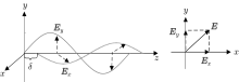
As shown in Fig. 1, the light propagates along the z axis, and the light vectors vibrate in the x– y plane.[32] For simplicity, we call this coordinate the propagation coordinate. On the plane expanded by the x and y axes, there are two orthogonal light vector components, Ex and Ey, which can be denoted as
where Ai (i = x, y) is the intensity of the light vector component, ϕ i (i = x, y) is the phase of the component, and ω is the angular frequency. The overall light vector E is the vector sum of Ex and Ey, i.e., E = Ex + Ey. To describe the polarization, the Stokes parameters are adopted, which are defined as
where δ = ϕ x − ϕ y is the phase error between the two orthogonal light vector components. For simplicity, the parameters are written as

If δ = 0 or δ = ± π , the light is in the linearly polarized state. If δ = ± π /2, it is in the circular polarization state. If δ ∈ (− π /2, π /2), it is in the ellipse polarization state. Actually, the linear and the circular polarization states are the extreme cases of the ellipse polarization states.
 | Fig. 1. Polarized light. |
For the circularly polarized light, there are two: the right-hand circularly polarized state and the left-hand circularly polarized state, categorized based on the phase delay between the two light vector components. When δ = π /2 + 2nπ , it is in the left-hand circular polarization state. If δ = − π /2 + 2nπ , it is in the right-hand circular polarization state. The principle of the circular polarization modulation method is based on the circular polarization states.
The polarization state is a stable property of polarized light, which will not be easily changed in light propagation. Thus, the polarization state can be used to convey information. Because of its stability in propagation and the obvious difference between the left-hand and right-hand polarization states, the circular polarization shows superiority in signal modulation than other polarization states. Circular polarization modulation is realized by changing the polarization states of the light. Providing a new way of modulating optical signals, circular polarization modulation is the basis of XCPolR. As shown in Fig. 2, the information appears in the form of polarization states. The left-hand circular polarization state represents “ 1” and the right-hand circular polarization state represents “ 0” . Each polarization state in Fig. 2 is called a slot, with a time duration of T. From Fig. 2, we know that the circularly polarized signal is actually a set of circularly polarized lights arranged in the time order and the ranging information is concealed in the polarization state sequence.
 | Fig. 2. Circular polarization modulation scheme. |
Based on the circular polarization modulation, we propose a novel ranging method using the circularly polarized x-ray, i.e., XCPolR, aiming at providing an accurate ranging measurement at long distance in deep space.
Generally, there are two kinds of ranging patterns: the transparent ranging pattern and the regenerative ranging pattern. The transparent ranging pattern emits the ranging signal and receives the reflected signal from the target object. By comparing the local signal with the reflected signal, the two-way delay is obtained and the range between the objects can be calculated. The flaw of this method is that the reflected signal has a low signal-to-noise ratio (SNR) because of the background noise and the reflection, which would have an effect on the ranging performance. Different from the transparent pattern, in the regenerative pattern, the target object regenerates the downlink signal based on the received uplink signal and sends it back to the transmitter. This will mitigate the influence of the background noise and bring a higher SNR for the downlink signal, which will consequently improve the ranging accuracy.
The range measurement could be between a spacecraft, the space station and another spacecraft, or between a spacecraft and a relay satellite. For simplicity, we use the master station and the slave station to denote the two ranging objectives. Figure 3 presents the block diagram of the XCPolR system. From the figure, we can see that the ranging system can be roughly divided into three parts: the master station, the space channel, and the slave station. According to Fig. 3, the signal processing procedure of XCPolR can be summarized as follows.
 | Fig. 3. Block diagram of XCPolR system. |
1) At the master station, modulate the x-ray signal with the binary ranging code using the circular polarization modulation method and send the circularly polarized x-ray signal to the slave station.
2) After space propagation, at the slave station, receive the circularly polarized uplink signal and demodulate the signal to recover the binary ranging sequence.
3) At the slave station, regenerate the downlink signal based on the recovered uplink signal and modulate the regenerated signal with the circular polarization modulation. Then sent it back to the master station.
4) At the master station, receive the downlink signal and demodulate the signal. Correlate the signal with the local ranging sequence to obtain the two-way time delay. Then calculate the range.
As indicated in Fig. 3, the uplink and the downlink share some similarity. Thus, in the following analysis, we put the emphasis on the uplink and the results can be extended to the downlink.
As described in Fig. 3, the signal processing of XCPolR can be divided into four parts. In the following, given the system structure, we model the signals in XCPolR mathematically and describe the signal processing procedure in detail. Through the signal processing procedure, we can gain a clear knowledge of the principle of XCPolR.
Firstly, at the master station, a binary ranging sequence is written as

where {ci}, i ∈ N, i < M is the ranging code, M is the length of the ranging code, and g(t) is the gate function, defined as
Here, {ci} can adopt the T4B pseudo-noise (PN) code suggested by the consultative committee for space data systems (CCSDS), which is a composite sequence formed by the combination of six periodic component PN sequences. The detailed T4B code structure can be found in Ref. [33].
The ranging sequence is modulated utilizing the circular polarization modulation, which converts the ranging sequence to circularly polarized x-ray. Based on the aforementioned Stokes parameters, the polarized signal s(t) can be written as

where Si is the Stokes parameters defined by Eq. (3), and Ψ (k) determines the polarization state to be either the left-hand circular polarization state or the right-hand circular polarization state
When k = 1, Ψ (k) represents the left-hand polarization state. Otherwise, it is the right-hand polarization state. Through Eq. (6), the binary ranging code is converted to the polarized x-ray signal. In essence, s(t) is a sequence of circularly polarized light arranged in time order. Each slot contains a certain polarization state with a time duration of T.
After the circular polarization modulation, s(t) is emitted by the master station and transmitted into deep space. According to the existing literatures, under certain conditions, the polarization states will not be changed during the deep space propagation.[29, 30, 34] Thus, at the receiver end, we can obtain the circularly polarized x-ray signal that contains the ranging information.
At the slave station, the circularly polarized x-ray from the master station, i.e., the uplink signal, is acquired and demodulated. In RF ranging, the ranging code is generally phase modulated on a sine carrier wave at radio frequency, and the carrier frequency and the ranging code rate are often coherent.[33] Differently, XCPolR utilizes the polarized light as the carrier wave and the ranging code is modulated on the polarized light. Thus, no carrier wave tracking exists in XCPolR. The successful acquisition relies greatly on the detection and demodulation of the polarized ranging signal.
Figure 4 gives the polarized x-ray signal detection and demodulation structure at the slave station end. After the deep space propagation, the polarized signal becomes

where τ ′ is the one-way time delay between the master station and the slave station. To demodulate the signal, the polarized x-ray signal should be converted to an electrical signal. The received signal first goes through a quarter wave plate (QWP). A wave plate is an optical device that can change the phase delay between the two orthogonal light vector components. For QWP, it can convert a circularly polarized light into a linearly polarized light. To express the conversion, the Mueller matrix[35] is adopted. The Mueller matrix is generally used to describe the property of optical devices and the conversion caused by the devices when light goes through them. The Mueller matrix of the wave plate can be defined as
where θ is the angle between the fast axis of the wave plate and the x axis of the propagation coordinate. The θ determines the phase delay caused by the wave plate. For QWP, let θ = π /2 in Eq. (9), and then the Mueller matrix for QWP can be expressed as
Then, the circularly polarized signal being through a QWP becomes

with
where Ψ is short for Ψ (r(t − τ ′ )). For the circularly polarized light, Ax = Ay = A and cos(Ψ ) = 0. Thus, equation (12) can be simplified as

 | Fig. 4. Circularly polarized light detection and demodulation scheme. |
Apparently, being through the QWP, the circularly polarized light is converted to a linearly polarized light. When the left-hand circularly polarized light is received, Ψ = π /2+ 2nπ and 
 | Fig. 5. Linearly polarized light: (a) channel l1, (b) channel l2. |
Then, the linearly polarized light goes through a polarization beam splitter (PBS). The function of the PBS is to separate two orthogonal linearly polarized lights into two independent channels, which are denoted as channel l1 and channel l2 for convenience. Taking channel l1 as an example, the light through the PBS could be written as

with

where 


As shown in Fig. 4, an optical analyzer is adopted to select the linearly polarized light of certain vibration directions. Only the linearly polarized light whose vibration direction accords with the transmission direction of the analyzer can pass through the analyzer. The analyzer can eliminate the influence of other light vector components with different vibration directions. The Mueller matrix of the analyzer is expressed as
where φ is the angle between the transmission direction and the x axis. For channel l1, φ = − π /4, then Ja(φ ) is
and the linearly polarized light becomes

where

Similarly, for channel l2, φ = π /4, and there is

with

Apparently, if the left-hand circularly polarized light is received at the slave station, Ψ = π /2 + 2nπ , and there are 

As described in the previous section, the circularly polarized light is converted into two channels of linearly polarized light. Next, the light signal is converted to an electric signal and the ranging code is demodulated from the electric signal.
In this system, a photoelectric detector is used to achieve the light-to-electric conversion. The output photoelectric current intensity is proportional to the intensity of the light. Then the x-ray signal can be detected by measuring the current intensity. To improve the detection accuracy and mitigate the noise influence, differential detection is used. Let i1 and i2 denote the currents generated by channels l1 and l2, respectively. Then, based on Eqs. (21) and (23), the currents in both channels can be expressed as
where η is the conversion efficiency, Ad is the area of the detector, Id is the dark current, Ith is the thermal noise current, and R is the detector impedance. Take the left-hand circularly polarized light as an example. If a time slot of left-hand circularly polarized light is received, i1 is

At the same time, at channel l2, we have

Thus, define the error current Δ i as

From Eq. (27), we know that the differential detection can mitigate the influence of the dark current and the thermal noise current. For the case of the right-hand circularly polarized light, we have

Obviously, by measuring the differential current output of the photoelectric detector, the circularly polarized ranging signal can be demodulated. At the same time, the influence of common mode noise can be mitigated in some degree because of the differential detection.
Let the recovered ranging code be denoted as 

where τ ′ is the unknown one-way time delay.
Based on the recovered signal, the downlink signal is regenerated at the slave station. The regeneration process could mitigate the background noise and boost the SNR of the downlink signal, which could greatly improve the performance of the ranging system. To regenerate the downlink signal, the phase delay of the received signal should be obtained. To calculate the phase delay, the received signal is correlated with the local signal.
Figure 6 gives the parallel correlators at the slave station. For each correlator, the received sequence is correlated with the T4B code components and their delays, which can be denoted as

 | Fig. 6. PN correlators. |
For each correlator, the maximum correlation value gives the position of the code component in the received sequence. With all the code component delays calculated, the overall time delay of the range signal can be calculated with the Chinese remainder theorem.[36] This delay is used for the regeneration of the downlink signal. After regeneration, the downlink signal is re-modulated and sent back to the master station. The receiving and processing of the downlink signal is similar to that of the uplink signal. Theoretically, the demodulated downlink signal at the master station has the form

where τ is the two-way time delay between the two stations and 
To calculate the time delay, the received downlink signal is correlated with the local ranging code. In practice, because the T4B code consists of a clock code component and a non-clock code component, the correlation process is divided into two parts: the non-clock component correlation and the clock component correlation. Let li be the length of Ci, and the non-clock component correlation process can be expressed as

where Ci is the i-th range code component and k = 0, 1, … , li − 1. With different delay indices k, different values of γ i are obtained. For each code component, the k with the maximum γ i determines the delay of Ci. By calculating the time delay of the non-clock components and adopting the Chinese remainder theorem, the total time delay in the unit of ranging clock period is obtained. The clock component is correlated with the local clock component to calculate the time delay within a clock period range. With the above calculated delays, the two-way time delay τ can be obtained. When τ is given, the range can be calculated accordingly,

where c is the speed of light.
Measuring accuracy is one of the most important parameters in a ranging system. For XCPolR proposed in this paper, various factors contribute to the measuring accuracy, including the Doppler effect, the differential demodulation, the correlation error, etc. To discuss the ranging accuracy, several conditions are assumed: 1) the detectors at both stations are well aligned; 2) there is no polarization distortion of the polarized x-ray signal during the deep space propagation.[30] In the following, the detailed analysis of the main factors that influence the ranging accuracy is accomplished.
The Doppler effect is common in signal measurement between two moving objects. For a mechanical wave, the motion of the source and the motion of the receiver have different impacts on the signal frequency. Different from the mechanical wave case, the Doppler effect of an optical wave depends only on the relative motion between the two objects. Either the light source moves towards the receiver or the receiver moves towards the source, which will have the same Doppler effect.
Let the velocity component along the propagation direction between the two stations be v. It should be noted that v can be either positive or negative. When the two stations are relatively moving away from each other, v is negative. Otherwise, v is positive. For XCPolR, the frequency of the ranging clock component is fc and fc = 1/(2T), where T is the slot duration. Because of the Doppler effect, the received clock component frequency is changed, denoted as 

where the denominator is the dilation parameter caused by the relativistic effects. And the slot duration is influenced,
When the downlink signal is sent back to the master station, the Doppler effect also exists. Thus, the ranging signal is influenced by a double Doppler effect
where 

Based on the aforementioned analysis, the impact of the Doppler effect on the range clock at the master station can be written as

and the relative error can be denoted as

From Eq. (38) we know that, because the speed of light is far larger than the relative speed, the period change caused by the Doppler effect will be very small. Also, the period changes approximately linearly with v for the same reason.
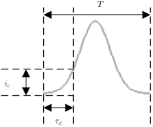
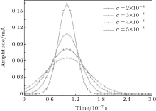
Besides the Doppler effect, there is also a delay caused by the differential demodulation at the photoelectric detector. The reason for differential demodulation is to mitigate the noise. But when the signal wave is distorted, it will also cause a detection error. Ideally, the current intensity in one time slot is constant, which can be seen as a square wave. Because of noise and the detector response property, the output current wave shape of the detector is usually distorted. Here, we model the error current in one time slot as a Gaussian function

where I is the error current intensity, σ d is the standard variance, and t ∈ [0, T]. For the convenience of calculation, the peak value of Δ i(t) is set at t = T/2. For the current detection, a threshold is set to mitigate the influence of noise. Only when the current intensity exceeds the threshold, will the start of the pulse be confirmed. As the signal model is not necessarily a square wave, the detection threshold ic will cause a time delay τ d for the detection, which is shown in Fig. 7. Let Δ i (τ d) = ic, we have
Then,

Taking into account the Doppler effect discussed in the previous section, at the slave station, the time delay can be rewritten as

Similarly, at the master station, the time delay caused by the differential detection is

Apparently, the detection delay depends on the threshold ic and the standard variance σ d. When τ d = 0, the right side of Eq. (41) is not zero. Thus, τ d is not necessarily above zero in some cases, which will be further discussed in the numerical simulation.
 | Fig. 7. Threshold detection. |
As described before, the accurate time measurement depends on the measure of the clock component in the ranging code. Thus, in this section, we only discuss the correlation of the clock component. Different from the non-clock components, the time measurement of the clock component is completed by correlating the clock component with the in-phase component code and the quadrature component code respectively.[33] Ideally, the ranging clock component is a square wave. Because of noise and low pass filtering, the ranging signal sequence is usually modeled as a sine function

where 

where n1(t) and n2(t) are white Gaussian noises with a power spectral density of N0/2. Because of the Doppler effect, the range clock frequency is influenced. Thus, at the master station
and Trc = 2π /wrc is the period of the received range clock.
To calculate the delay, rc(t) is correlated with the local in-phase and the quadrature signal respectively. As defined in Ref. [33], C1(t) is a square wave,

where ci = 1 when i = 2k and ci = − 1 when i = 2k + 1. Equation (48) satisfies TC1 = Trc/2. Then, the correlation process could be denoted as
Then, let Tcor be the correlation time. For calculation simplicity, Tcor is an integral multiple of Trc, i.e., Tcor = mTrc. Thus,
For the second part of Eq. (51), we have
Thus, equation (51) can be calculated as
Similarly,

Thus, τ can be calculated as

and

Based on the relation between the power spectral density and the correlation function, 


Then, equation (56) can be rewritten as
Substituting Eqs. (51) and (54) into Eq. (58) leads to the following relationship:
As Trc = 2π /ω rc, equation (59) can be simplified as
If the Doppler effect is taken into account, the range clock is influenced and 
According to Eq. (61), the SNR of the range clock can be defined as

In this section, numerical simulation is carried out to evaluate the performance of XCPolR. The slot duration of the circularly polarized signal is set to be T = 2 × 10− 7 s. Similar to the assumption given in the error analysis, in the numerical simulation, we assume that: 1) the detectors at the stations have been well aligned; 2) the polarization states will not be changed during the space propagation.
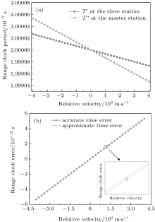
The relative velocity between the two stations is set as v ∈ [− 4000 m/s, 4000 m/s]. Here, the relative velocity means the relative motion between the two objectives in the signal propagation direction. Figure 8 gives the influence of the Doppler effect on the range clock. Figure 8(a) is the range clock influenced by the Doppler effect at the slave and the master stations. The x axis denotes the relative velocity and the y axis is the range clock influenced by the Doppler effect. It can be seen that when the stations are moving closer, the range clock period decreases. Otherwise, the period increases. Besides, the Doppler effect has a larger impact on the range clock at the master station than that at the slave station. Figure 8(b) gives the error between the received range clock period and the real range clock period at the slave station. It is clearly shown that the Doppler effect on the range clock is relatively small and the time error is approximately linear with v. The reason for this is the huge difference between the speed of light and the relative velocity. If we eliminate v at the denominator of Eq. (38), we could define an approximate Doppler time error 

The 


 | Fig. 8. Doppler effect simulation: (a) influence of the Doppler effect on the range clock, (b) range clock error caused by the Doppler effect at the slave station. |
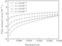
In this section, we discuss the impact of the differential demodulation on the time measure. Figure 9 gives the time measure error caused by the differential demodulation. The x axis of the figure is the detection threshold and the y axis is the time measure error. From the figure, we can clearly see that with the increasing detection threshold, the time measure error will also arise accordingly. We can also know from Fig. 9 that there are negative values for the time error. These negative values are caused by the inaccuracy of the model. For the ideal signal, at t = 0, the signal intensity is zero. But for the signal modeled as a Gaussian function, the value is not necessarily zero at t = 0, for example, a positive value g. Thus, when the detection threshold is smaller than g, the time will become negative, which should be eliminated.
Besides, the standard variance of the Gaussian model is another factor that influences the time measure error. The reason for the influence is that the threshold detection depends on the shape of the pulse, which is determined by the standard variance of the Gaussian model. From Fig. 9 we can see that under the same detection threshold, the time measure error varies with the value of σ d. Under the same detection threshold, the detection error is lower with larger σ d. This is because with larger σ d, the Gaussian model shares more similarities with the real signal. As shown in Fig. 10, with the same pulse power, the shape of the Gaussian model varies with the standard variance. With larger standard variance, the Gaussian function is flatter. At the same time spot before the peak value point, the function with a larger standard variance has a larger value, which in turn means this model could take less time to reach the same function value than that with a smaller standard variance. It can be seen that at t = 0, the function value is not necessarily zero because of the model error. This is also the reason for the negative values in Fig. 9.
 | Fig. 9. Differential demodulation error. |
 | Fig. 10. Gaussian models with different standard variances. |
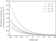
Let L be the length of the T4B code. The correlation time is set to be an integral multiple of the range sequence length, i.e. Tcor = mLT (m ∈ N+ ). The correlation error simulation is presented in Fig. 11. The x axis of the figure is the SNR of the range clock component and the y axis is the standard variance of the correlation error.
 | Fig. 11. Correlation error simulation. |
In Fig. 11, each line corresponds to a different ratio of Tcor to T. From the figure, we can see that with the increasing SNR of the range clock, the standard variance of the correlation error decreases accordingly. Thus, a higher SNR could help improve the performance of the range system. This also demonstrates the necessity of the regenerative mechanism, which can boot the downlink SNR. It can also be seen that the correlation error is related to the ratio of Tcor to T. With a lower ratio of Tcor to T, the correlation error is relatively larger than that with a higher ratio.
A novel x-ray ranging method based on the circular polarization modulation, named as x-ray circularly polarized ranging, is documented in this paper. This method utilizes the circularly polarized x-ray signal to convey the ranging information, which takes advantage of both the high energy property of x-ray and the fine stability of the circular polarization states in deep space. The principle of the proposed method was described and the signals in XCPolR were modeled mathematically. Besides, the main factors that affect the ranging accuracy were analyzed with both theoretical analysis and numerical simulation. The numerical simulation showed that the range clock is influenced by the Doppler effect, but the impact is small when the relative velocity is small. Besides, the differential demodulation could cause a detection error and the error is related to the signal model. What is more, the correlation error is related to the SNR of the range clock and the ratio of the correlation time to the slot duration.
Given its inherent property and advantages, XCPolR provides a potential option for future deep space range measurement. Besides, the proposed method could motivate the further research in and development of man-made x-ray applications in deep space exploration.
| 1 |
|
| 2 |
|
| 3 |
|
| 4 |
|
| 5 |
|
| 6 |
|
| 7 |
|
| 8 |
|
| 9 |
|
| 10 |
|
| 11 |
|
| 12 |
|
| 13 |
|
| 14 |
|
| 15 |
|
| 16 |
|
| 17 |
|
| 18 |
|
| 19 |
|
| 20 |
|
| 21 |
|
| 22 |
|
| 23 |
|
| 24 |
|
| 25 |
|
| 26 |
|
| 27 |
|
| 28 |
|
| 29 |
|
| 30 |
|
| 31 |
|
| 32 |
|
| 33 |
|
| 34 |
|
| 35 |
|
| 36 |
|