

Interface-guided mode of Lamb waves in a two-dimensional phononic crystal plate*
[Huang Ping-Pinga) , Yao Yuan-Weia)†  , Wu Fu-Gen
b) , Zhang Xina) , Li Jinga) , Hu Ai-Zhena) ]
, Wu Fu-Gen|
|


†Corresponding author. E-mail: yaoyw@scut.edu.cn
*Project supported by the National Natural Science Foundation of China (Grant Nos. 11374068 and 11374066), the Science & Technology Star of Zhujiang Foundation of Guangzhou, China (Grant No. 2011J2200013), and the Natural Science Foundation of Guangdong, China (Grant No. S2012020010885).
We investigate the interface-guided mode of Lamb waves in a phononic crystal heterostructures plate, which is composed of two different semi-infinite phononic crystal (PC) plates. The interface-guided modes of the Lamb wave can be obtained by the lateral lattice slipping or by the interface longitudinal gliding. Significantly, it is observed that the condition to generate the interface-guided modes of the Lamb wave is more demanding than that of the studied fluid–fluid system. The interface-guided modes are strongly affected not only by the relative movement of the two semi-infinite PCs but also by the thickness of the PC plate.
Since the concept of phononic crystals (PCs) was explicitly put forward in 1993, periodic materials or structures, which own the elastic wave band gap, have attracted wide attention.[1, 2] The phononic bandgap (PBG) that suppresses the propagation of any elastic/acoustic wave mode, regardless of the polarization or wave vector, is a major feature of a PC. The existence of PBG means that a PC may be designed for use in elastic or acoustic waveguides, or filters.[3– 5] Based on this mechanism, a great deal of work has been devoted to the study of PC waveguides, which are regarded as one of the most promising applications.[6– 16]
Recently, scientists have extended their study from the traditional phononic waveguide model to the two-dimensional (2D) PC heterostructures, which are composed of two different semi-infinite PCs. For example, Zhao et al. have investigated two kinds of heterostructures in two-dimensional mercury/CCl4 PC.[17] Their results showed that the interface states could be created either by lateral lattice slipping or by increasing the interface separation in the SCSC heterostructure, which is defined as two semi-infinite PCs of the heterostructure composed of circular cylinders with different filling ratios in square lattices. However, for the RRTC heterostructure, which is composed of two semi-infinite PCs consisting of rectangular cylinders in a rectangular lattice and circular cylinders in a triangular lattice, the interface-guided modes can be generated without any relative movement. The effect of the dislocation defects on the guided modes in the gaps of two-dimensional mercury/water squared PC heterostructures has been studied by Zhao et al.[18] Their results indicated that the transverse, longitudinal dislocation could generate guided modes at the interface. However, the available papers have only discussed the interface guided mode in a two-dimensional liquid/liquid PCs system. It is well known that there is only a longitudinal wave in this infinite fluid system. Very recently, the investigation of Lamb waves has become a popular topic.[19– 24] Theoretical and experimental studies of the band structure of Lamb waves in a finite system have revealed that the band structure of a Lamb wave in a 2D finite PC was entirely different from that of the infinite PC with the same geometry and composition.[19] Because Lamb waves are stress-free elastic waves coupling by transverse wave and longitudinal wave in a certain thickness PC plate, the formation of a Lamb waves interface state may be more complex and the Lamb waves interface-guided mode will perform different propagation behaviors.[25] This means that it is worth investigating the guided modes for Lamb waves in PC heterostructures.
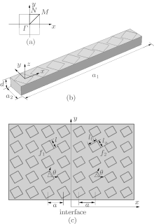
In the present paper we will first study the interface modes of the heterostructures when there is lateral lattice slipping or interface longitudinal gliding. The heterostructures are composed of two semi-infinite phononic crystal plates with rotating square/rectangular scattering cylinders embedded in a matrix martial, as shown in Fig. 1. Then, we make a comparison of the studied fluid– fluid system and two-dimensional PC plate with the same cylinder and lattice. The results show that the condition to generate the interface-guided modes of the Lamb wave is more demanding than that of the fluid– fluid system. Finally, the effects of the thickness of the PC plate are investigated. It is found that the number and the frequency position of the interface-guided modes are strongly affected by the thickness of the plate.
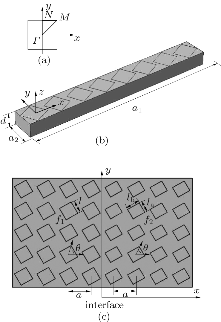 | Fig. 1. (a) The first Brillouin zone of two-dimensional square lattice. (b) A schematic diagram of a supercell of PC heterostructure. (c) A x– y plane section sketch illustrating the heterostructure. |
We calculate the band gap structures for such heterostructures with the use of the finite element method (FEM) in combination with a supercell technique. The size of the supercell should be chosen to be large enough to guarantee that the coupling effect between neighboring supercells is negligible. The geometry of a supercell PC plate is depicted in Fig. 1(b). Here, the supercell can be chosen as a rectangle containing m × 1 unit cells in each of the two different lattices. In our calculations, we take m = 4, and the primary vectors of this supercell are a1(2m, 0)a and a2 = (0, 1)a, where a is the lattice constant of the square lattices. The structure has a finite size in the z direction and the plate thickness is d. The periodic boundary conditions are applied to the sides of supercell along the x and y directions based on Bloch’ s theorem. The conditions in terms of displacement up could be defined as
where kx and ky are the components of the Bloch wave vectors in the x and y directions, respectively.
In our study, the material of the scattering cylinders and the host material are tungsten and rubber, respectively. The physical parameters are chosen as follows: ρ = 17800 kg/m3, E = 3.6 × 10¹¹ Pa, v = 0.27 for tungsten, ρ = 1300 kg/m3, E = 1.2 × 10⁷ Pa, and v = 0.47 for rubber.
Firstly, we survey the interface modes in the system where the semi-infinite phononic crystal plate has a relative lateral slip, as shown in Fig. 2. From Fig. 2(a), it can be seen that the interface is parallel to the y axis and the rotating angles θ of the square/rectangular cylinders are the same. The difference between the two semi-infinite phononic crystals is the filling fraction of cylinders, which is denoted as f1 and f2, respectively. The short-side, long-side lengths of the individual rectangular cylinders and the relative lateral slipping separation between the two different PCs are denoted by la, lb, and Δ x, respectively. As shown in Fig. 2(a), the PML subdomains are used to model the infinite domains at the top and the bottom. In the horizontal direction, phase-shifted periodic boundary conditions are used. A load on the exicitor boundary acts as a source and the detector is placed on the receiver boundary.
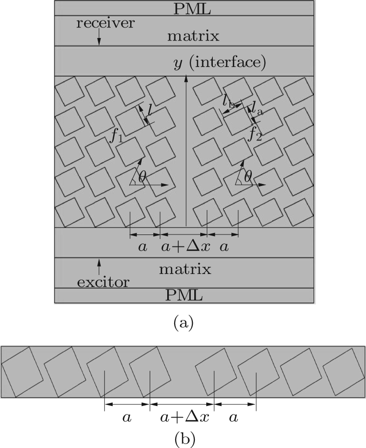 | Fig. 2. (a) The x– y plane section sketch illustrating the heterostructure with a lateral slipping separation Δ x. (b) The supercell of the heterostructure used to calculate the PBG. |
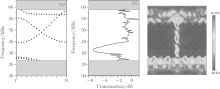
In order to obtain the maximum PBG width of the prototype heterostructure PC, we conduct a great deal of calculation by changing the filling fraction of cylinders f, the aspect ratio of the rectangular cylinders la/lb, and the rotating angles θ . We obtain the optimal structural parameters as f1 = 0.533, f2 = 0.501, la/lb = 0.844, and θ = 27° . Meanwhile, the supercell used to calculate the PBG of the heterostructure is shown in Fig. 2(b). Now, we focus on the case where the lateral slipping separation Δ x is 0.55 mm with a slab thickness of d = 0.5 mm. The band structure, the transmission power spectra (TPS) and the transmission displacement field are calculated and shown in Fig. 3.
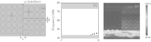
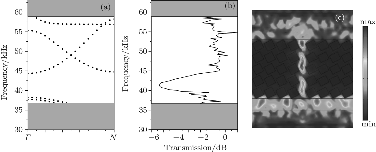 | Fig. 3. (a) The band structure for the heterostructure. (b) TPS for the heterostructure with relatively lateral slipping separation Δ x = 0.55 mm, f1 = 0.533, f2 = 0.501, d = 0.5 mm, and θ = 27° . The gray regions delimit the PBG for the prototype heterostructure. (c) The calculated transmission displacement field at the frequency f = 49.15 kHz. |
In Fig. 3(a), the PBG for the prototype heterostructure PC is delimited by two gray regions. From the panel, it is easy to find that three guided modes lie completely in the PBG frequency range. Figure 3(b) displays the TPS corresponding to the band structure. Aided by the calculated transmission field, we find the transmission frequency interval of the interface-guided mode, which means that the Lamb wave is well confined within the interface and, guided with weak losses, extends from 44.00 kHz to 58.25 kHz, and covers a large part of PBG. This indicates that the guided Lamb waves in this frequency region can propagate through the PC heterostructure when there is a lateral lattice slip. Here, it is necessary to point out that there are some transmission values greater than 0 dB in the transmission spectra. This phenomenon is caused by the use of force (load) as the input instead of incident Lamb wave when using COMSOL Mutiphysics, and this does not affect the numerical results.[26] In order to testify that the guided mode is the interface-guided mode, the FEM was utilized to calculate the displacement field. For example, the displacement field of the heterostructure is calculated when the lateral slipping separation Δ x is 0.55 mm and the frequency is 49.15 kHz. It is obvious that the displacement filed is mainly distributed in the interfacial space and the guided wave propagates along the interface direction, as shown in Fig. 3(c). We also calculate the displacement field of the heterostructure in the other frequency. These results indicate that interface-guided modes appear in the heterostructure when there is a lateral lattice slip. The formation mechanism of the interface-guided mode is as follows: as the interface space increases, the lowest point of the transmission bands moves down from the upper edge of the PBG of the prototype heterostructure, falls into the PBG, and becomes the guided modes. If the interface is too narrow, then the descent of the lowest point of the transmission bands is small, so the transmission bands will lie beyond the PBG, and naturally no localized interface state exists. The formation mechanism shows that the lateral slipping separation has an influence on the behavior of the interface-guided mode. Further investigation reveals that the number of guided modes gradually increases as the lateral slipping separation ranges from 0.05 mm to 1 mm. With the increase of the lateral lattice separation, all of the guided modes are moved downwards from the upper edge to PBG.
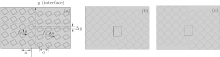
We also investigate the character of the interface mode when the interface longitudinal gliding is introduced. As shown in Fig. 4(a), two PCs on either side of the interface have relatively gliding separation Δ y in the y direction, with other geometrical and physical parameters remaining unchanged. The rectangular area with a blue boundary is the supercell of the heterostructure, which is used for calculating the PBG.
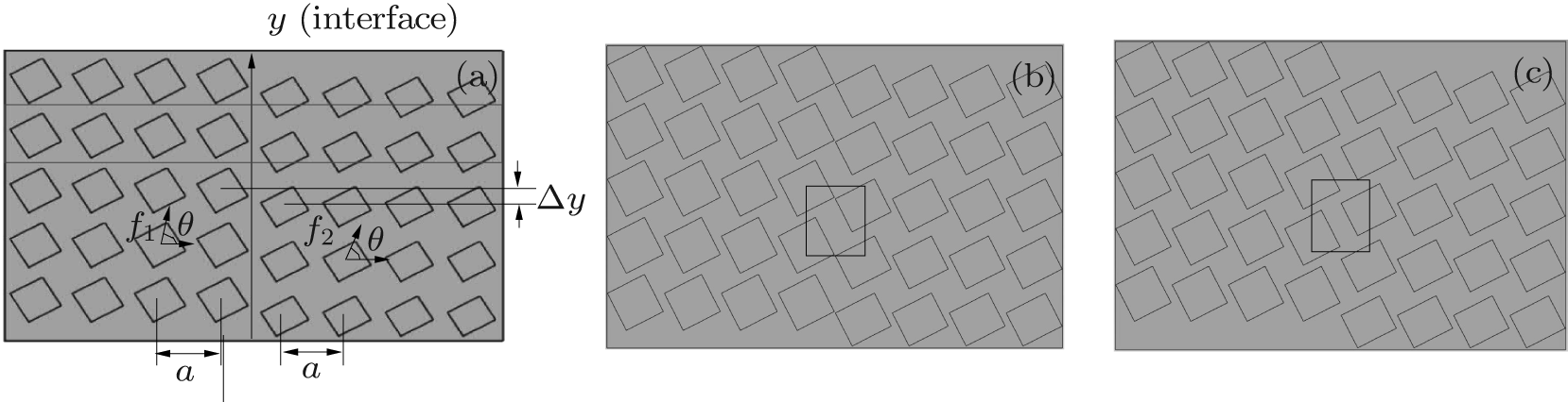 | Fig. 4. (a) An x– y plane section sketch illustrating the heterostructure with a longitudinal gliding separation Δ y. (b) and (c) The heterostructure for Δ y = 0.3 mm and 0.5 mm, respectively. |
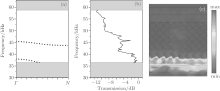
The band structure of the heterostructure, with the gliding separation Δ y = 0.3 mm, is shown in Fig. 5(a). Two guided modes move upwards from the lower edge of the PBG to the region of the PBG. One guided mode only extends over part of the ky region, and the other guided mode completely lies in the frequency range of the PBG. The corresponding TPS also displays a transmission frequency interval of the interface-guided mode between 44.75 and 46.73 kHz for the latter, as shown in Fig. 5(b). The transmission displacement field at a single frequency of 45.75 kHz for the guided mode of the heterostructures is also given in Fig. 5(c). From these panels, it is clear that the displacement field is almost distributed in the interfacial cavity composed of four nearest scatterers at the interface. Compared to the lateral slip, the localization of the field is not obvious. Further studies show that when the scatterer has an appropriate size to form a nearly closed cavity (as shown in Fig. 4(b)), a localized interface state appears. It is also found that when Δ y < 0.3 mm. The guided modes move upwards from the lower edge of PBG with the increase of the gliding separation. However, when the gliding separation exceeds 0.3 mm, these guided modes move downwards, and finally disappear in the lower edge of the PBG. When the longitudinal separation is too large (see Fig. 4(c)), the cavity formed in the heterostructure is almost open and no energy can be stored. Hence, no cavity mode exists.
 | Fig. 5. Supercell calculation of (a) the band structure and (b) the TPS for the heterostructure after introducing relatively longitudinal gliding separation Δ y = 0.3 mm with f1 = 0.533, f2 = 0.501, d = 0.5 mm, and θ = 27° . The gray regions delimit the PBG for the prototype heterostructure. (c) The calculated displacement field at the frequency f = 45.75 kHz. |
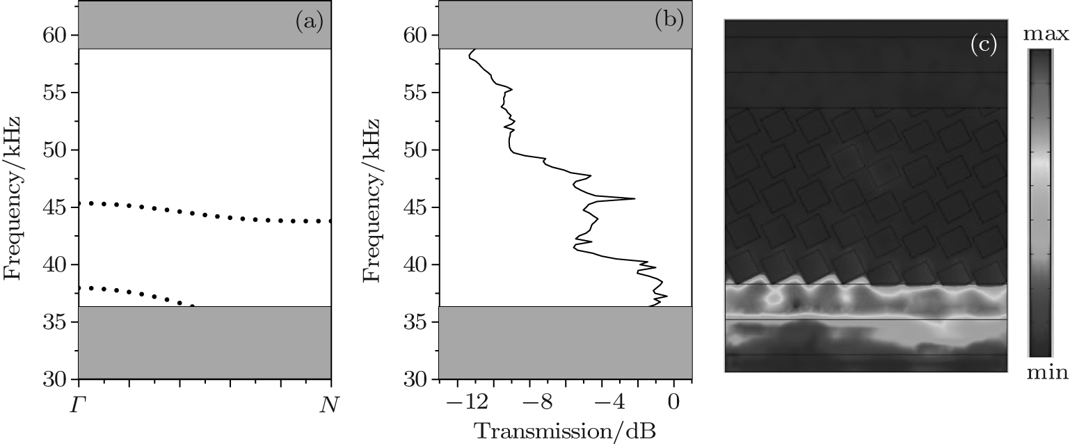
In the previous fluid– fluid system, the authors did not present similar results. Now, we make a further comparison of the heterostructure by introducing interface longitudinal gliding between the previously studied fluid– fluid system and the two-dimensional PCs plate. The lattice structure to be investigated, which is displayed in Fig. 6(a), is similar to the SCSC heterostructure depicted by Zhao.[17] The band structure of the Lamb wave is shown in Fig. 6(b) with d = 0.5 mm and the longitudinal gliding separation Δ y = 0.35 mm. It is found that the PBG of the prototype heterostructure lies in the frequency range from 43.20 kHz to 73.49 kHz. Although there are four bands in the frequency range from 43.20 to 45.89 kHz in the PBG, they are not the interface-guided mode. This conclusion can be found from the displacement field at the frequency f = 44.45 kHz. The mode can go through the whole right semi-infinite PC, as shown in Fig. 6(c). Thus, it is not the interface-guided mode. Nevertheless, for the fluid– fluid system, there exist three guided modes lying in the PBG, and they survive over most of the frequency range of the absolute PBG.[18] The results indicate that it is difficult to generate broadband interface-guided modes in a two-dimensional PC plate. In other words, the formation conditions of the guided modes are more demanding.
 | Fig. 6. (a) Schematic configuration of the SCSC heterostructure. (b) The band structure for Lamb wave PC heterostructure after introducing longitudinal gliding separation Δ y = 0.35 mm. The filling fraction is f1 = 0.65 and f2 = 0.7. The gray regions delimit the absolute PBG for the prototype heterostructure. (c) The calculated displacement field at the frequency f = 44.45 kHz. |
The above results show that the lateral slipping, longitudinal gliding separation can generate guided modes at the interface. Because Lamb waves are stress-free elastic waves coupled by a transverse wave and a longitudinal wave in a PC plate of a certain thickness, it is interesting to investigate the effect of the thickness of the plate on the behavior of the guided mode. Keeping other geometric parameters the same as those in Fig. 2. Figure 7 shows the band structures of the heterostructure with d being 0.1, 0.15, 0.5, and 0.8 mm. From the figures, it is observed that the PBG width and the number of guided modes change when the thickness is altered. There are three guided modes in the band structures of the heterostructure with d = 0.1 mm, as shown in Fig. 7(a). These modes only extend over some ky region. However, when the thickness d = 0.15 mm, there appear four guided modes in PBG. One of these guided modes extends over the whole ky region, while others only extend over some ky region, as shown in Fig. 7(b). Figure 7(c) shows that three guided modes completely lie in the region of the PBG. There are six guided modes in the PBG of the heterostructure with d = 0.8 mm, as displayed in Fig. 7(d). These panels show that the number of interface-guided modes increases with increasing thickness. This is ascribed to the participation of the Z mode (SH mode). As the thickness increases, the number of Z modes grows and the coupling between XY mode and Z mode becomes strong, resulting in the increase in the number of Lamb wave modes. Consequently, the number of interface-guided modes increases. These results demonstrate that the interface-guided modes are sensitive to the thickness d.
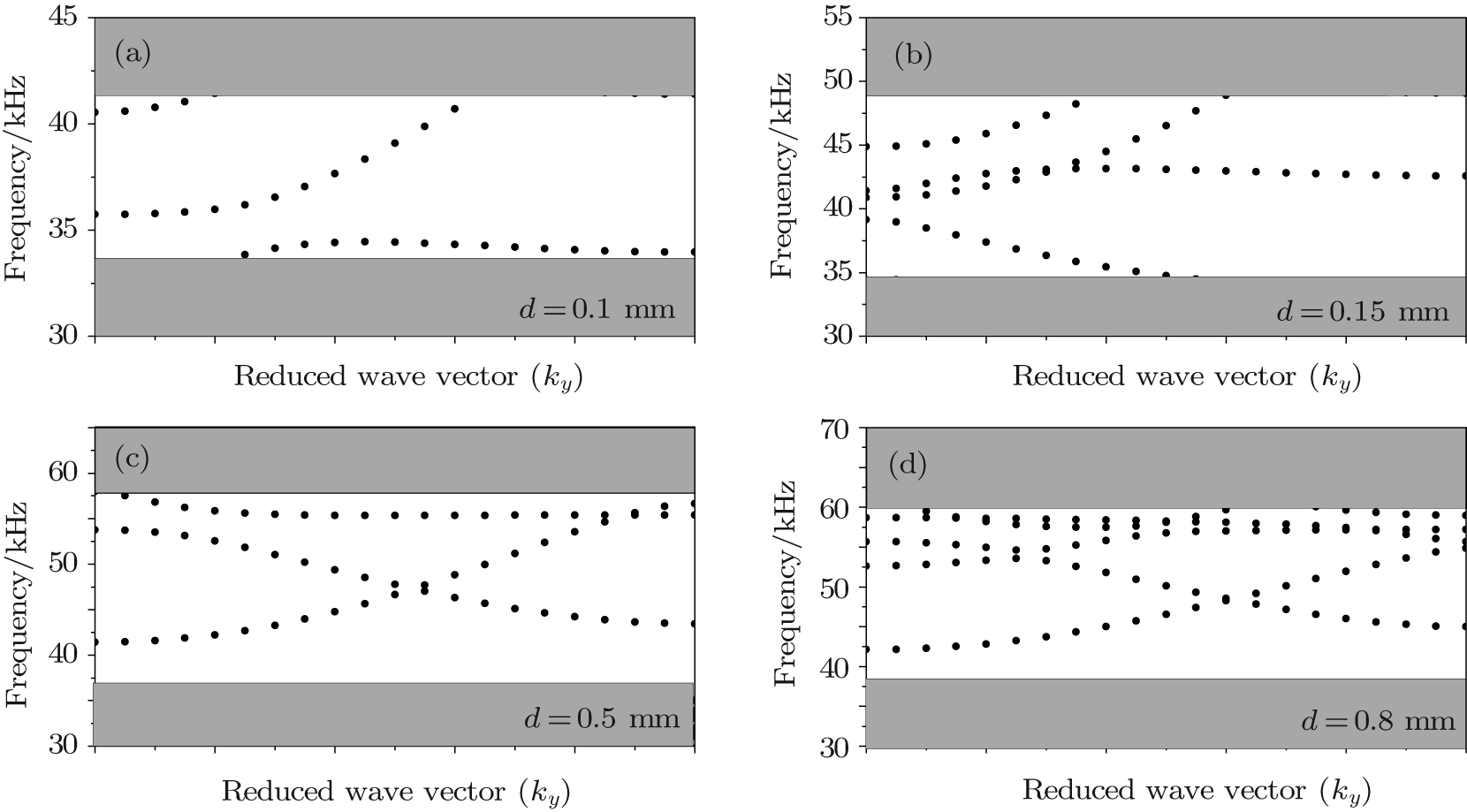 | Fig. 7. Band structures of the heterostructures after introducing relatively lateral slipping separation Δ x = 0.55 mm with f1 = 0.533, f2 = 0.501, and θ = 27° . The gray regions delimit the PBG for the heterostructure. The thickness (a) d = 0.1 mm, (b) d = 0.15 mm, (c) d = 0.5 mm, and (d) d = 0.8 mm. |
In conclusion, we have studied the interface-guided modes for a Lamb wave in a 2D phononic crystal heterostructures constituted by two different semi-infinite PCs. The band structures, TPS, and the transmission displacement fields of the heterostructures were calculated by the finite element method in combination with a supercell technique. The obtained results demonstrate that the interface-guided modes can be generated by lateral lattice slipping or by the interface longitudinal gliding. The number of interface-guided modes relies greatly upon the lateral slipping separation or longitudinal gliding separation. Significantly, it is observed that the condition to generate the interface-guided modes of the Lamb wave is more demanding than that of the studied fluid– fluid system. Moreover, our numerical results show that the number and the frequency position of the interface-guided modes are strongly affected by the thickness of the plate.
| 1 |
|
| 2 |
|
| 3 |
|
| 4 |
|
| 5 |
|
| 6 |
|
| 7 |
|
| 8 |
|
| 9 |
|
| 10 |
|
| 11 |
|
| 12 |
|
| 13 |
|
| 14 |
|
| 15 |
|
| 16 |
|
| 17 |
|
| 18 |
|
| 19 |
|
| 20 |
|
| 21 |
|
| 22 |
|
| 23 |
|
| 24 |
|
| 25 |
|
| 26 |
|