

Tunable and broadband microwave frequency combs based on a semiconductor laser with incoherent optical feedback*
[Zhao Mao-Ronga) , Wu Zheng-Maoa) , Deng Taoa) , Zhou Zhen-Lia) , Xia Guang-Qionga), b)†  ]
]
]
|
|


†Corresponding author. E-mail: gqxia@swu.edu.cn
*Project supported by the National Natural Science Foundation of China (Grant Nos. 61178011, 11204248, 61475127, and 61275116), the Natural Science Foundation of Chongqing City, China (Grant Nos. 2012jjB40011 and 2012jjA40012), and the Open Fund of the State Key Lab of Millimeter Waves of China (Grant No. K201418).
Based on a semiconductor laser (SL) with incoherent optical feedback, a novel all-optical scheme for generating tunable and broadband microwave frequency combs (MFCs) is proposed and investigated numerically. The results show that, under suitable operation parameters, the SL with incoherent optical feedback can be driven to operate at a regular pulsing state, and the generated MFCs have bandwidths broader than 40 GHz within a 10 dB amplitude variation. For a fixed bias current, the line spacing (or repetition frequency) of the MFCs can be easily tuned by varying the feedback delay time and the feedback strength, and the tuning range of the line spacing increases with the increase in the bias current. The linewidth of the MFCs is sensitive to the variation of the feedback delay time and the feedback strength, and a linewidth of tens of KHz can be achieved through finely adjusting the feedback delay time and the feedback strength. In addition, mappings of amplitude variation, repetition frequency, and linewidth of MFCs in the parameter space of the feedback delay time and the feedback strength are presented.
Under external disturbances, such as optical injection, optical feedback, and optoelectronic feedback, semiconductor lasers (SLs) can behave in diverse nonlinear dynamical states including period, multiple-period, chaos, frequency locking, regular pulsing, quasi-periodic pulsing, chaotic pulsing, etc.[1– 13] The nonlinear dynamics of SLs have been extensively studied and can be applied in optical chaotic communications, [14, 15] random number generation, [16– 19] all-optical frequency conversion, [20] radio-over-fiber transmission, [21] and laser chaos-based lidar, [22] radar[23] and sensors.[24] Recently, the application of the nonlinear dynamics in SLs has been extended into the generation of microwave frequency combs (MFCs), and some schemes have been successfully proposed and investigated. Chan et al. proposed a generation approach of MFCs based on harmonic frequency-locked pulsing states output from an SL under negative optoelectronic feedback (NOEF).[25] However, limited by the electronic bandwidth of the feedback loop, the obtained MFCs only have a bandwidth of a few GHz, and large amplitude variation and severe nonharmonic spurious noise from the residual of the delay frequency also restrict their potential applications. As a result, Lin et al. proposed another scheme which is based on an SL subjecting to optical pulse injection from an optoelectronic feedback laser.[26] In such a scheme, by optically injecting a regular pulsing (RP) state output from a master laser (ML) subjected to optoelectronic feedback into a slave laser (SL), MFCs with low nonharmonic spurious noise and 20 GHz bandwidth within a flatness of ± 5 dB have been obtained experimentally.
In this paper, based on an SL under incoherent optical feedback, a simple system is proposed for the generation of MFCs. Compared with an optoelectronic feedback system, the incoherent optical feedback system has an inherent superiority in that its bandwidth is not limited by the electronic bandwidth due to all-optical components used in such system. Utilizing the RP states outputting from this incoherent optical feedback system, tunable and broadband MFCs can be obtained. Furthermore, the influence of the operation parameters on the amplitude variation, the line spacing (or repetition frequency), and the linewidth of the MFCs have been investigated numerically.
Figure 1 is a schematic diagram of our proposed system for generating tunable and broadband MFCs based on an SL with incoherent optical feedback. A horizontally polarized beam outputting from an edge-emitting semiconductor laser (SL) is firstly rotated 45° by a Faraday rotator (ROT), after passing through a neutral density filter (NDF), and then is incident upon a mirror (M). The reflected beam by the mirror, after passing through the NDF and ROT again, is rotated additional 45° and converted into a vertically polarization beam. Such a vertically polarized beam is re-injected into the SL and forms incoherent optical feedback. In this system, the NDF is used to adjust the feedback strength.
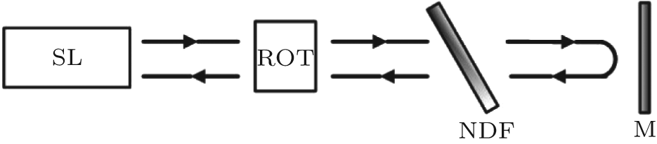 | Fig. 1. Schematic diagram for generating tunable and broadband MFCs. SL: semiconductor laser; ROT: Faraday rotator; NDF: neutral density filter; M: mirror. |
The dynamic characteristics of an SL subjecting to incoherent optical feedback can be described by[27]

where S(t) and N(t) are the time-dependent photon density and carrier density, respectively. τ p is the photon lifetime, τ s is the carrier lifetime, τ is the feedback delay time, κ f is the feedback strength, Γ is the confinement factor, I is the bias current, V is the active region volume, γ is the gain ratio of the TM mode (transverse magnetic mode) and the TE mode (transverse electric mode), e is the charge of an electron, β is the spontaneous emission factor, χ is the Gauss white noise, and G(N) is the optical gain in the laser cavity and can be expressed as

where Gn is the differential gain coefficient, and N0 is the carrier density at transparency.
The rate equations (1) and (2) can be numerically solved by the fourth-order Runge– Kutta method. During the calculations, the used data are: e = 1.6 × 10− 19 C, τ p = 3 ps, τ s = 2.5 ns, Γ = 0.3, N0 = 1.25 × 1024 m3, γ = 1, Gn = 2.1 × 10− 12 m3/s, V = 1× 10− 16 m3, β = 1× 10³ s− 1. Based on the above given parameters, the threshold current Ith (= eV[1/(Γ Gnτ p) + N0]/τ s) of a solitary SL is about 12.9 mA.[28]
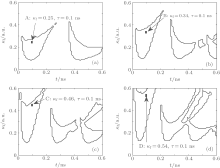
In this work, since the generation of MFCs is based on the RP state of an SL under incoherent optical feedback, the operation parameters required for achieving the RP state in the SL under incoherent optical feedback should first be determined. Obviously, in this system, the bias current of the SL, the feedback delay time τ , and the feedback strength κ f are three key operation parameters. Figure 2 shows the regions of the RP states in the parameter space of feedback delay time τ and feedback strength κ f under different bias currents, where the regions surrounded by black bold lines characterize the RP states. From this diagram, it can be observed that, with the increase of the bias current, the RP state regions are expanded significantly.
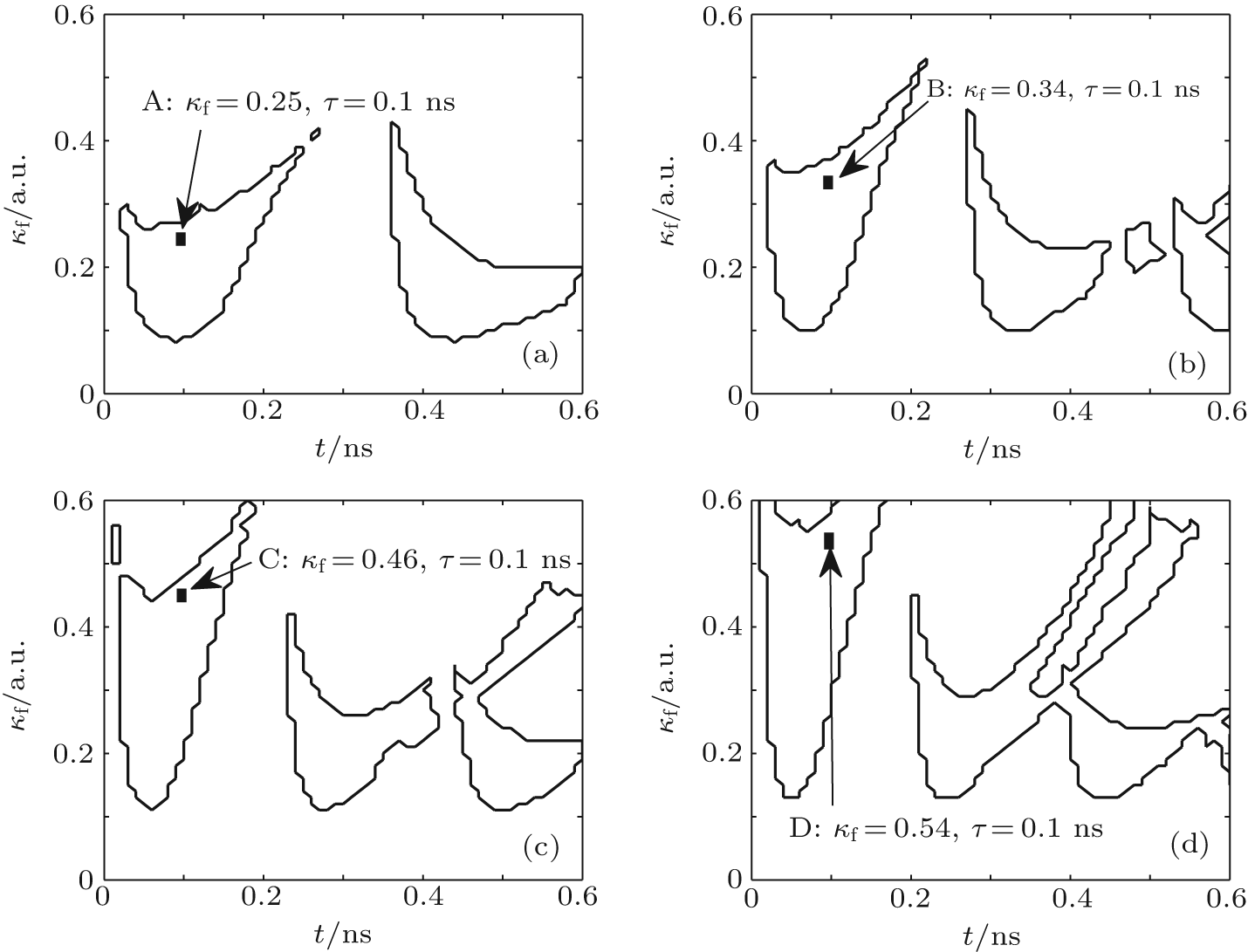 | Fig. 2. RP regions in the parameter space of feedback delay time τ and feedback strength κ f for (a) I = 1.5Ith, (b) I = 2Ith, (c) I = 2.5Ith, and (d) I = 3Ith. |
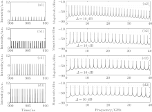
Further calculations show that the characteristics of the generated MFCs are different when τ and κ f take different values. In the following, we will discuss the performance of the MFCs for the parameters taken as those labeled points A, B, C, and D in Fig. 2, respectively. From point A to point D, the feedback delay times are all 0.1 ns, and (I, κ f) are (1.5Ith, 0.25), (2Ith, 0.34), (2.5Ith, 0.46), and (3Ith, 0.54), respectively. Figure 3 displays the pulse trains (left column) and corresponding power spectra (right column) under different values of (I, κ f). As shown in Fig. 3(a), which corresponds to point A in Fig. 2, the generated MFC has a bandwidth of about 20 GHz. Meanwhile, the line spacing is 1.32 GHz. Here, the bandwidth is defined as the frequency width within a 10 dB amplitude variation (Δ ). For point B in Fig. 2, as shown in Fig. 3(b), the generated MFC has a bandwidth of about 30 GHz. Meanwhile, the line spacing is 1.69 GHz. Furthermore, the generated MFCs corresponding to points C and D in Fig. 2 have also been given in Figs. 3(c) and 3(d), respectively, and the MFCs have a bandwidth of about 32 GHz with 1.87 GHz line spacing and a bandwidth of about 40 GHz with 2.11 GHz line spacing, respectively. Therefore, through adjusting the operation parameters, MFCs with different bandwidths and line spacings can be acquired.
 | Fig. 3. Pulse trains (left column) and corresponding power spectra (right column) of the RP state in the SL with incoherent optical feedback, where (a)– (d) correspond to points A-D in Fig. 2, respectively. |
Generally, the magnitude of amplitude variation is a key index for MFCs. Here, we focus on the amplitude variations of the generated MFCs within a frequency range of 30 GHz. Figure 4 simulates the mappings of the amplitude variations Δ in the parameter space of the feedback delay time τ and the feedback strength κ f. As shown in this diagram, under the four given bias currents, the amplitude variation Δ of the generated MFCs can all be lower than 20 dB in the frequency range of 30 GHz through selecting suitable τ and κ f. Moreover, the increase of the bias current is helpful for improving the amplitude flatness and enlarging the regions of the MFCs with low amplitude variation. Especially, for I = 3Ith, within 30 GHz frequency range, the amplitude variations of generated MFCs are almost smaller than 10 dB, and the minimum value of Δ is 3.9 dB. Compared with the commercial circuit-based generated MFCs with typically ± 20 dB amplitude variation in a 20 GHz range (for example, Picosecond Pulse Labs Model 7112 Comb Generator[29]), the MFCs generated by an SL with incoherent optical feedback have better performance.
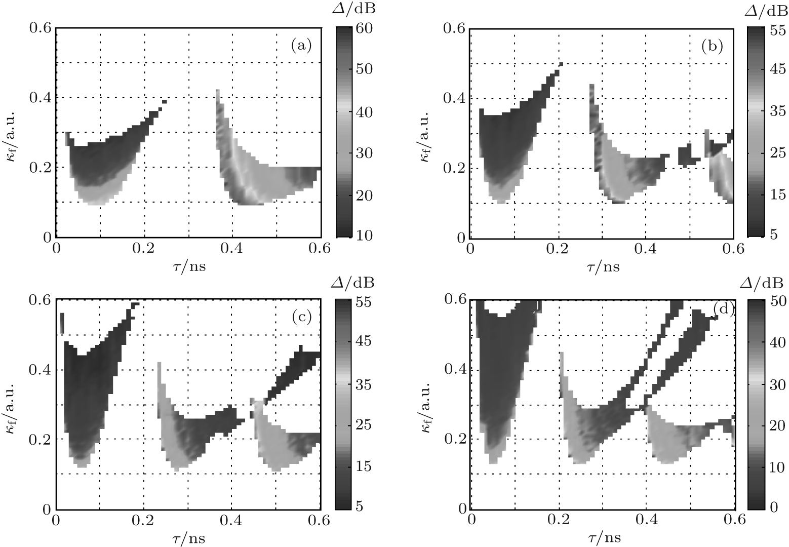 | Fig. 4. Mappings of the amplitude variation Δ evolutions of the generated MFCs as functions of the feedback delay time τ and the feedback strength κ f, where (a) I = 1.5Ith, (b) I = 2Ith, (c) I = 2.5Ith, and (d) I = 3Ith. |
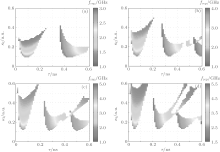
For practical applications, it is usually expected that the line spacing of MFCs can be easily tuned through adjusting the related operation parameters. In this system, the line spacing of the generated MFCs is equal to the repetition frequency of RP. Therefore, it is necessary to investigate the dependences of the repetition frequency of MFCs on the feedback delay time and the feedback strength. Figure 5 shows the mappings of the repetition frequency frep of RP state in the parameter space of feedback delay time τ and feedback strength κ f under (a) I = 1.5Ith, (b) I = 2Ith, (c) I = 2.5Ith, and (d) I = 3Ith. It is clear that, for a fixed delay time τ , the repetition frequency frep almost decreases with the increase of the feedback strength κ f. However, for a fixed feedback strength κ f, the evolution trend of frep with the feedback delay time τ is much more complicated. For the left RP regions, with the increase of the feedback delay time τ , the repetition frequency frep will firstly decrease, and then exhibit an increasing tendency. However, for the other RP regions, the repetition frequency frep almost decreases with the increase of the feedback delay time τ for a fixed feedback strength κ f. Additionally, the tunable range of frep increases with the increase of the bias current. For the four given bias currents, the repetition frequency frep of RP (or the line spacing of the generated MFCs) can be tuned in the range of about 1.02– 5.37 GHz.
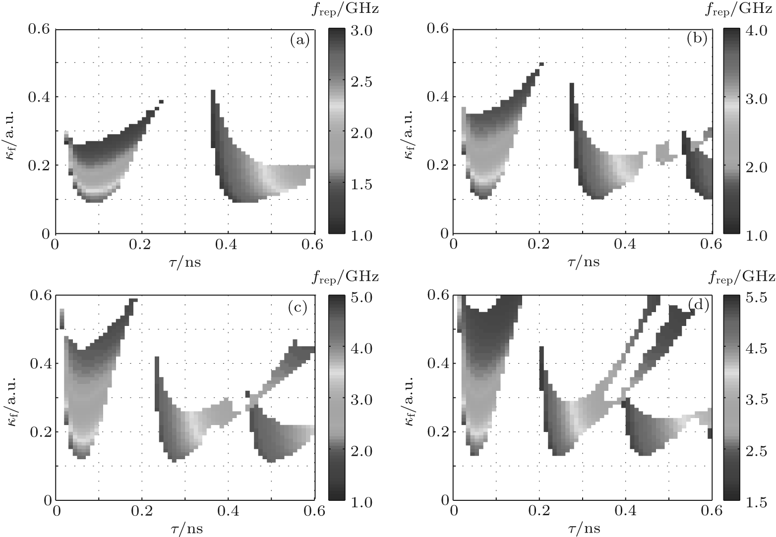 | Fig. 5. Mappings of the repetition frequency frep of RP in the parameter space of feedback delay time τ and different feedback strength κ f, where (a) I = 1.5Ith, (b) I = 2Ith, (c) I = 2.5Ith, and (d) I = 3Ith. |
Finally, we will investigate the spectral purity of the generated MFCs, which is another key index of MFCs and can be characterized by the microwave spectral linewidth of RP state. The microwave spectral linewidth Δ f quoted in this paper is the standard deviation of the spectral power distribution, [30] and it can be described by

with

where P(ν ) is the output power distribution of RP state in the SL, and ν is the frequency. In this work, we use the linewidth of the 1st harmonic of the RP state to describe the linewidth of the MFCs.
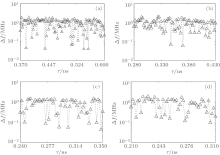
Figure 6 indicates the dependence of the linewidth Δ f of the 1st harmonic of the RP state on the feedback delay time τ for κ f = 0.2 under different bias currents. As shown in this diagram, the linewidth Δ f is mainly on the order of MHz and can be decreased to tens of KHz. Moreover, the linewidth Δ f is very sensitive to the variation of feedback delay time τ . As a result, the feedback delay time τ needs to be finely controlled in order to obtain high spectral purity MFCs. Further calculations also show that, for a fixed value of τ , the variation of Δ f with the feedback strength κ f exhibits a similar tendency.
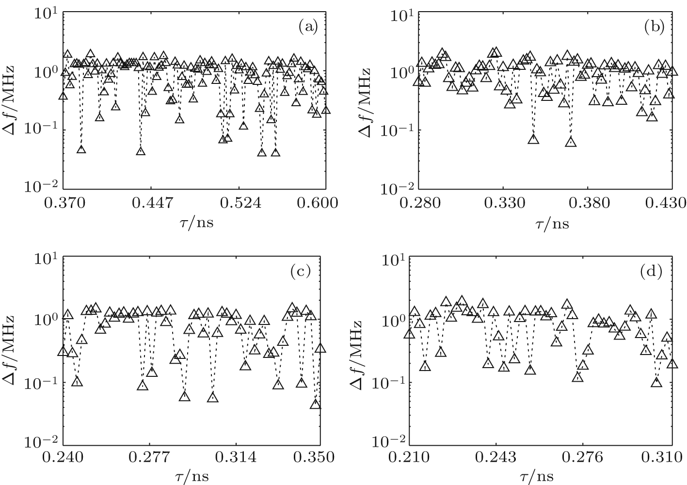 | Fig. 6. Δ f versus the feedback delay time τ under κ f = 0.2, where (a) I = 1.5Ith, (b) I = 2Ith, (c) I = 2.5Ith, and (d) I = 3Ith. |
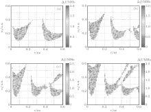
To specially describe the influence of feedback delay time τ and feedback strength κ f on linewidth Δ f, figure 7 integrates the evolution of Δ f in the parameter space of the feedback delay time and the feedback strength under different bias currents. From this diagram, one can see that Δ f varies in the range from tens of KHz to a few MHz, and the influence of the bias current has no obvious regularity. Thus, in order to achieve high spectral purity MFCs, related operation parameters of the system must be controlled precisely.
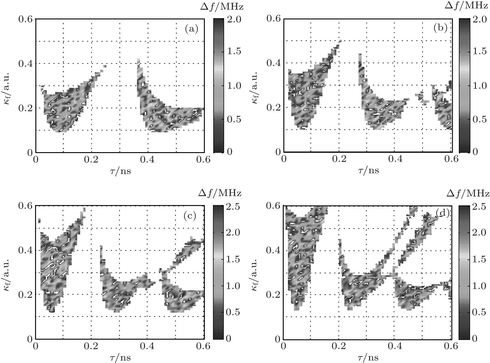 | Fig. 7. Mappings of Δ f in the parameter space of the feedback delay time τ and the feedback strength κ f, where (a) I = 1.5Ith, (b) I = 2Ith, (c) I = 2.5Ith, and (d) I = 3Ith. |
In summary, we have proposed and numerically characterized a generation scheme of tunable and broadband MFCs based on an SL with incoherent optical feedback. Utilizing the RP states in an SL with the incoherent optical feedback, an MFC, whose bandwidth is greater than 40 GHz within a 10 dB amplitude variation, can be generated. Increasing the bias current is helpful for improving the amplitude flatness and enlarging the regions for generating MFCs with low amplitude variation. For I = 3Ith, within a frequency range of 30 GHz, the minimum amplitude variation of the generated MFCs is 3.9 dB. The line spacing of MFC monotonously decreases with the increase of the feedback strength. However, the influence of the feedback delay time on the line spacing of MFC is much more complicated. Meantime, the tunable range of the line spacing can be enlarged through increasing the bias current. The linewidth of the MFC characterized by the linewidth of the 1st harmonic of the RP state is very sensitive to the feedback delay time and feedback strength. Through precisely controlling the operation parameters, the linewidth of generated MFC can be reduced to tens of KHz.
| 1 |
|
| 2 |
|
| 3 |
|
| 4 |
|
| 5 |
|
| 6 |
|
| 7 |
|
| 8 |
|
| 9 |
|
| 10 |
|
| 11 |
|
| 12 |
|
| 13 |
|
| 14 |
|
| 15 |
|
| 16 |
|
| 17 |
|
| 18 |
|
| 19 |
|
| 20 |
|
| 21 |
|
| 22 |
|
| 23 |
|
| 24 |
|
| 25 |
|
| 26 |
|
| 27 |
|
| 28 |
|
| 29 |
|
| 30 |
|