


Trajectory and frequency of vortex gyration in a multi-nanocontact geometry*
[Li Hua-Nana), b) , Liu Yana)†  , Jia Min
a) , Du Ana) ]
, Jia Min|
|


†Corresponding author. E-mail: liuyanphys@mail.neu.edu.cn
*Project supported by the National Natural Science Foundation of China (Grant No. 11404053) and the Fundamental Research Funds for the Central Universities of Ministry of Education of China (Grant No. n130405011).
Nonlinear vortex gyrotropic motion in a three-nanocontacts system is investigated by micromagnetic simulations and analytical calculations. Three out-of-plane spin-polarized currents are injected into a nanodisk through a centered nanocontact and two off-centered nanocontacts, respectively. For current combination ( ip1, ip0, ip2) = (−1, 1, −1), the trajectory of the vortex core is a peanut-like orbit, but it is an elliptical orbit for ( ip1, ip0, ip2) = (1, 1, −1). Moreover, the gyrotropic frequency displays peaks for both current combinations. Analytical calculations based on the Thiele equation show that the changes of frequency can be ascribed mainly to the forces generated by the Oersted field accompanying the currents. We also demonstrate a dependence of eigenfrequency shifts on the direction and distance of the applied currents.
Magnetic vortices are observed typically in patterned or continuous soft magnetic thin films, and they can be characterized by two vortex integers: the polarity p and the chirality c. The term p = 1 (p = − 1) corresponds to upward (downward) magnetization orientation of the vortex core (VC), and the term c = 1 (c = − 1) corresponds to the counterclockwise (clockwise) rotation sense of the in-plane curling magnetization.[1, 2] The vortex has received extensive attention because of its practical applications in information storage devices, [3, 4] spin-transfer microwave oscillators, [5] and magnetic memory.[6] Moreover, it has been demonstrated very recently that nanomagnets with a single magnetic vortex structure can destroy cancer cells.[7, 8] Research into vortex dynamics mainly focuses on the gyrotropic motion, switching of the VC, and the control of the vortex chirality. The first successful manipulation of magnetic vortex was by magnetic field, [9– 11] and more recently, studies have especially focused on the dynamics driven by an out-of-plane spin-polarized dc current by means including metallic nanopillars, [12– 17] nanocontacts, [18– 26] and magnetic tunnel junctions.[27, 28] With the deepening explorations of vortex dynamics, the Oersted field (OH) induced by current was proven to be important in vortex dynamics. For example, the teams of Liu and Yakata both found that OH could control the chirality of the vortex.[17, 29] Nakatani et al. reported that the OH should be taken into account in simulations of VC reversal.[30] Choi et al. observed that the eigenfrequency becomes higher or lower in vortex gyrotropic motion, depending on whether the vortex chirality is parallel or anti-parallel to the direction of the OH.[15]
However, the OH in these studies was relatively simple and perfectly symmetric. Consider that three point-con-tact spin-torque devices have been demonstrated ex-pe-ri-men-tally.[31, 32] In this letter, we design a new model, wherein the spin-polarized currents are injected into a permalloy (Py) nanodisk through three independent nanocontacts. In this model, the distribution of OH is not circular symmetry but considerably complex, which results in a nonlinear response of the VC displacement to the spin-polarized currents, and the frequency spectra shows multiple peaks.
A Py nanodisk of radius R = 200 nm and thickness L = 10 nm is chosen as the model and its ground state is a vortex with polarity and chirality (p, c) = (1, 1), as illustrated in Fig. 1. Three out-of-plane spin-polarized currents are applied to the nanodisk through three independent nanocontacts. For simplicity, we assume that three spin-polarized currents with the same current density (J) will pass through each of the individual contacts, and the radii of the three contacts are Rc = 50 nm, where the spin polarization of the currents are all assumed to be Sp = − 1, pointing in the − z direction. The contacts are located in the y axis of the disk symmetrically, and their center-to-center distance d is chosen to be 100, 110, 125, and 150 nm, respectively. The direction of the applied current is defined as ip = + 1 (− 1), corresponding to the + z (− z) direction. Accordingly, we choose (ip1, ip0, ip2) = (− 1, 1, − 1) and (ip1, ip0, ip2) = (1, 1, − 1) to study the vortex gyration, the subscripts p0, p1, and p2 indicate the current located in the center of the disk and the other two currents in the y axis, respectively.
To conduct micromagnetic simulations of vortex gyrotropic motion, we use OOMMF code, which is based on the Laudau– Liftshitz– Gilbert equation, extended by the Slonczewski spin-transfer torque.[23, 33] In the simulation, the nanodisk is discretized into many small cells, each with size 2.5 nm× 2.5 nm× 10 nm, and the magnetic parameters used for Py are as follows: the saturation magnetization Ms = 8.6 × 10⁵ A/m, the exchange constant A = 1.3 × 10− 11 J/m, P = 0.4 is the degree of spin polarization, and the Gilbert damping parameter α = 0.05. The OH accompanying the currents is calculated using Biot– Savart’ s law.
In our previous work, three dynamic phenomena have been observed in this system: 1) no vortex excitation, 2) VC gyrotropic motion, and 3) formation of a new configuration in sequence with increasing J, where the critical current density between different dynamics is dependent on the current direction and d.[34]
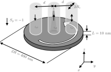
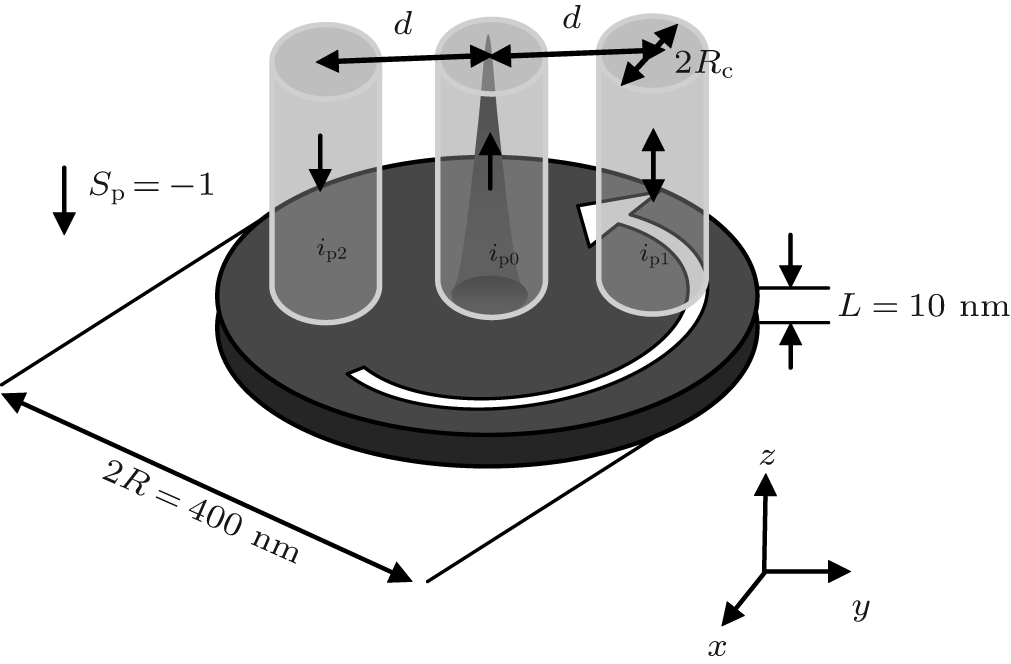 | Fig. 1. Schematic of the model system. The polarized currents are applied via three nanocontacts represented by white cylinders with radius Rc. The radius of the Py nanodisk is R and its thickness is L. The ground state for the Py disk is a vortex with (p, c) = (1, 1), with p and c indicated by the out-of-plane cone and the white arrow, respectively. |
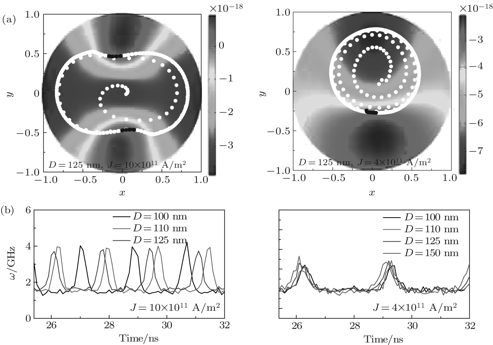 | Fig. 2. (a) The trajectories of VC (white dots) for current combinations (ip1, ip0, ip2) = (− 1, 1, − 1) and (ip1, ip0, ip2) = (1, 1, − 1). (b) The instantaneous frequency (ω ) of VC as a function of simulation time with the same J and various d for two current combinations. The black dots represent the positions where the frequency peaks appear. The background shows the contour plots of the Oersted field energy versus the VC position. |
Here we focus on the second dynamic behavior, the VC gyrotropic motion. Figure 2(a) shows the trajectory of VC for the two current combinations. The VC experiences spiral motion until reaching a steady-state orbit. However, it should be stressed that the steady-state orbit is obviously distinct from the previously observed circular trajectory for the case of one nanocontact. It has been known that in one nanocontact structure, the potential is circularly symmetrical and the corresponding steady trajectory is a single circular orbit.[23] For our model, the orbits are clearly affected by the direction of the currents. For (ip1, ip0, ip2) = (− 1, 1, − 1), the trajectory is a peanut-like shape, but for (ip1, ip0, ip2) = (1, 1, − 1), it is an elliptical orbit. Such characteristic trajectories should correlate with the distributions of OH generated by currents. The background in Fig. 2(a) shows the total OH energy versus the VC position in the disk. For (ip1, ip0, ip2) = (− 1, 1, − 1), the OH energy is symmetric, and it shows high values in the middle region, so the VC endeavors to avoid the high energy region when it is rotating in the disk. In other words, the high energy forces the VC to the low region, which induces the slender waist of the peanut-like trajectory. For (ip1, ip0, ip2) = (1, 1, − 1), the elliptical trajectory is in excellent agreement with its OH energy distribution, the higher OH energy in the bottom region of the disk results in an elliptical trajectory. Therefore, we can attribute these characteristic trajectories to the non-circular symmetry of the OH energy.
Actually, a special VC motion absolutely corresponds to a certain frequency mode, [18, 35– 37] and the distorted orbits imply that the gyrotropic frequency may depend on the VC position. Now we turn to investigating the instantaneous frequency of the VC. The instantaneous frequency Δ φ /Δ t with φ (t) = arctan(y/x), where φ is the angular position of VC in polar coordinates, and x and y are the rectangular components of the VC position vector. Figure 2(b) shows the gyrotropic frequency changing in time for the same J and different d. We can see that the frequency shows two peaks in one period when (ip1, ip0, ip2) = (− 1, 1, − 1), where the peaks always appear at the positions marked by the black dots on the VC trajectory. For (ip1, ip0, ip2) = (1, 1, − 1), the frequency shows only one peak in one period, where the peaks corresponding to the positions are marked with black dots on the trajectory (Fig. 2(a)).
To elucidate the underlying physics of the observed gyrotropic frequency and to search for key parameters for reliably controlling the frequency of VC oscillations, an analysis of the forces acting on the VC motion is necessary. It has been established that the motion of VC is well described by the Thiele equation[38]

where X = (x, y) is the position vector of the VC. The first term in Eq. (1) is the gyroforce, where the gyrovector is given by G = − Gẑ with gyroconstant G = 2π pMsL / γ , where γ is the gyromagnetic ratio. The second term is the damping force. The damping tensor is expressed as

where b is the core radius. The third term is the restoring force, which is due to the change of the system energy. The total energy can be written as Wtot = Wm + W0 + W1 + W2, where Wm, W0, W1, and W2 are the magnetostatic energy, the Oersted field energy arising from the centered current J0 and the other two off-centered currents J1 and J2, respectively. From previous work, we know that the magnetostatic energy Wm = κ 0 | X| 2/2, where 

Here, Hn is the Oersted field in the disk plane arising from the three currents. In our calculations, we assume that the currents flow uniformly through a perfectly cylindrical cross section underneath each of the individual nanocontacts. The last term is the spin-transfer force,

where FST0, FST1, and FST2 are the spin-transfer force caused by the centered current and the two off-centered currents, respectively. It is given by

and

where θ , and φ are the polar and azimuth angels of magnetizations. In the calculations, we use the two-vortices ansatz to describe the in-plane components and the bell-shaped ansatz for the out-of-plane magnetization component of a moving vortex.[23] In addition, h is Planck’ s constant, P is the degree of spin polarization, μ 0 the vacuum permeability, and e the electron charge. The subscript pcn denotes integration over the regions underneath the individual nanocontacts. Based on Eqs. (1)– (3), the gyrotropic frequency of VC can be described as

where

The superscript r indicates the radial component of the force. According to Eq. (4), we obtain the VC gyrotropic frequency ω for the two current combinations, as shown in Fig. 3, where D = 125 nm, J = 10, 4× 10¹¹ A/m2. We can see the effects of OH forces on the frequency in Figs. 3(a) and 3(b). If we take only 


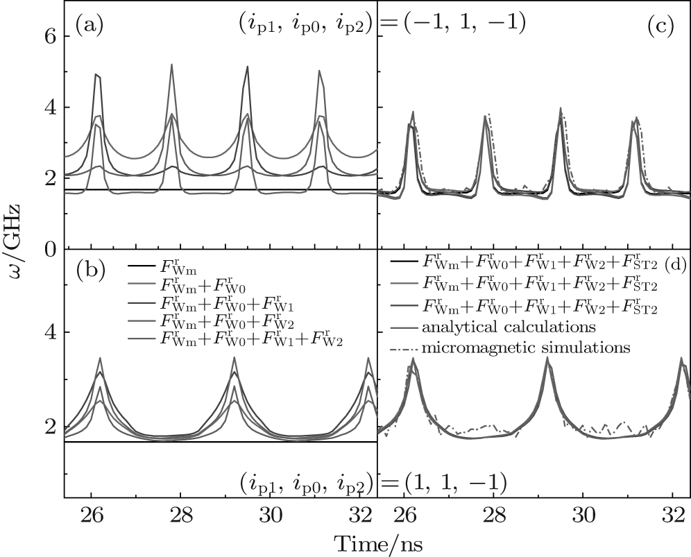 | Fig. 3. The calculated instantaneous frequency of VC as a function of simulation time: (a) and (b) when only considering the Oersted field force, and (c) and (d) also taking FST into account, where the J and d are the same as those in Fig. 2(a). |
In order to further clarify the contribution of each force to the change of ω , we plot the frequency change Δ ω , which refers to the magnitude of frequency originating from different forces in one cycle, as shown in Fig. 4. Figure 4(a) shows the VC orbits in one cycle, where the red star and black dot mark the two peaks of frequency for (ip1, ip0, ip2) = (− 1, 1, − 1) and the black dot indicates the frequency peak for (ip1, ip0, ip2) = (1, 1, − 1). Figure 4(b) diagrams the frequency induced by different forces in one cycle, where Δ ω 0, Δ ω 1, Δ ω 2, Δ ω ST0, Δ ω ST1, and Δ ω ST2 indicate the frequencies caused by 


 | Fig. 4. a) Indication of the specific positions in one cycle of VC orbits. The red star and black dot mark the positions where the frequency shows two peaks for (ip1, ip0, ip2) = (− 1, 1, − 1), and the black dot indicates the position where the frequency shows one peak for (ip1, ip0, ip2) = (1, 1, − 1). (b) The frequency induced by different forces in one cycle. Δ ω 0, Δ ω 1, Δ ω 2, Δ ω ST0, Δ ω ST1, and Δ ω ST2 indicate the frequency originating from       |
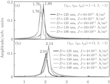
The changes of the instantaneous frequency inevitably create eigenfrequency shifts. The eigenfrequency represents the average rotation frequency of the VC in one period. To analyze quantitatively how such a complicated OH influences the eigenfrequency of VC, we performed fast Fourier transform (FFT) on the 〈 mx〉 . The eigenfrequency of VC is about 1.53 GHz for the nanodisk employed here. Figures 5(a) and 5(b) show the FFT spectra for the two current combinations with different d and J. For (ip1, ip0, ip2) = (− 1, 1, − 1), the fundamental frequency is insensitive to the current density at a fixed d; its value is concentrated in a range of ∼ 1.89 GHz. However, with the decrease of d, the frequency shifts to lower values. In sharp contrast, as the FFTs spectra for current combination (ip1, ip0, ip2) = (1, 1, − 1) show, the fundamental frequency increases with the increasing J at a fixed d, whereas the eigenfrequency shifts from 2.01 GHz to 2.14 GHz when J increases from 2 × 10¹¹ A/m2 to 4 × 10¹¹ A/m2. But for the same current density, the main frequency shows no dependence on d. Let us look at this problem from another angle: actually, the changes of eigenfrequency also reflect the period (T) of VC gyration on the steady trajectory. For (ip1, ip0, ip2) = (− 1, 1, − 1), T increases with the decrease of d at a fixed J, but for (ip1, ip0, ip2) = (1, 1, − 1), T is sensitive only to J; it has no correlation with d.
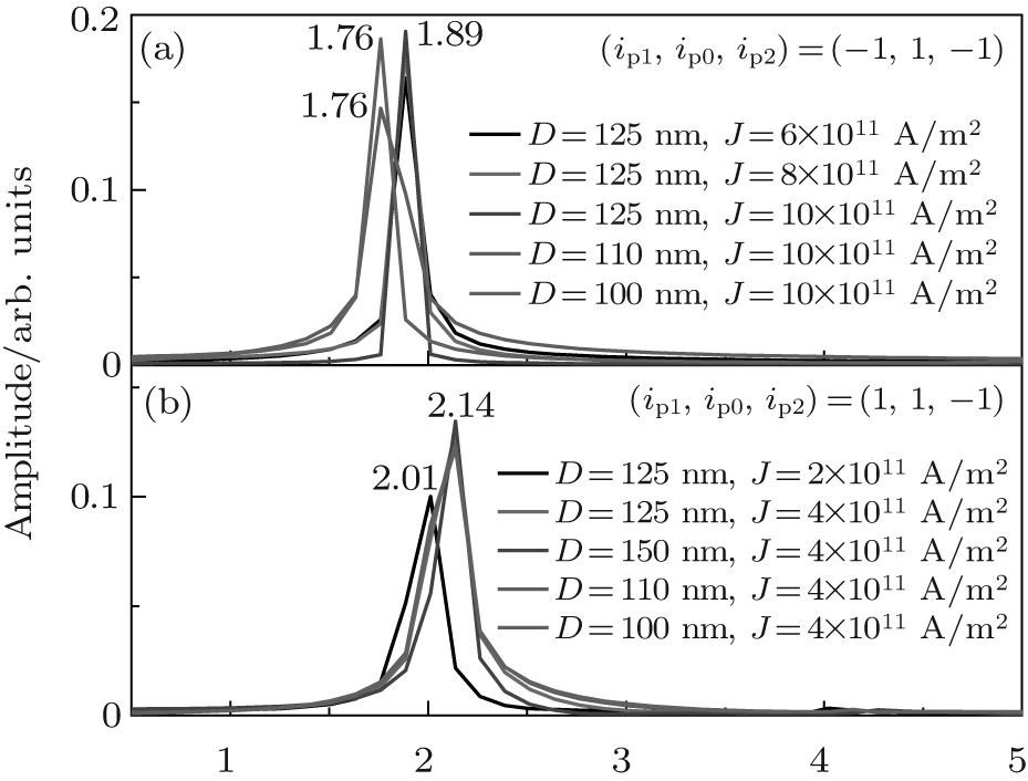 | Fig. 5. (a) and (b) The Fourier spectra of 〈 mx〉 dependence on the current density and contact distance for (ip1, ip0, ip2) = (− 1, 1, − 1) and for (ip1, ip0, ip2) = (1, 1, − 1), respectively. |
In summary, using a three-nanocontact structure, we find a nonlinear response of magnetic vortices to the currents. This reveals that the frequency, an intrinsic dynamic characteristic of a given vortex state, is controllable by changes in the direction, magnitude, and inter-distance of spin-polarized out-of-plane dc currents. Analytical calculations indicate that Oersted field force plays a key role in the behavior of VC gyrotropic frequency. The present work provides a reference for frequency-tunable oscillators without additionally applied magnetic fields. In addition, the phenomenon of frequency dependence upon the position on the trajectory can probably be used to control the VC motion and reversal.
| 1 |
|
| 2 |
|
| 3 |
|
| 4 |
|
| 5 |
|
| 6 |
|
| 7 |
|
| 8 |
|
| 9 |
|
| 10 |
|
| 11 |
|
| 12 |
|
| 13 |
|
| 14 |
|
| 15 |
|
| 16 |
|
| 17 |
|
| 18 |
|
| 19 |
|
| 20 |
|
| 21 |
|
| 22 |
|
| 23 |
|
| 24 |
|
| 25 |
|
| 26 |
|
| 27 |
|
| 28 |
|
| 29 |
|
| 30 |
|
| 31 |
|
| 32 |
|
| 33 |
|
| 34 |
|
| 35 |
|
| 36 |
|
| 37 |
|
| 38 |
|