†Corresponding author. E-mail: gaojs@ciomp.ac.cn
*Project supported by the National Natural Science Foundation of China (Grant No. 61401424).
In this paper, we present an infrared transparent frequency selective surface (ITFSS) based on iterative metallic meshes, which possesses the properties of high transmittance in infrared band and band-pass effect in millimeter wave band. Cross-slot units are designed on the iterative metallic meshes, which is composed of two same square metallic meshes with a misplaced overlap. In the infrared band of 3–5 μm, the ITFSS has an average transmittance of 80% with a MgF2 substrate. In the millimeter wave band, a transmittance of −0.74 dB at the resonance frequency of 39.4 GHz is obtained. Moreover, theoretical simulations of the ITFSS diffractive characteristics and transmittance response are also investigated in detail. This ITFSS may be an efficient way to achieve the metamaterial millimeter wave/infrared functional film.
A frequency selective surface (FSS) is an artificial periodic structure, which consists of two-dimensional array of metallic patches or apertures in a thin conducting film, that has been widely used as a filter in the microwave and millimeter wave band.[1– 4] High conductive metals are always selected in the classical FSS to achieve high filtering effect, but these metals will lower the transmittance of FSS in the infrared band, which limits the FSS applications in several fields, such as an aircraft dome.[5– 8] Therefore, an infrared transparent FSS (ITFSS), which possesses high transmittance in infrared band for imaging sensor and band-pass effect in millimeter wave band for receiving radar signal, needs to be developed. In earlier work, [9– 12] we have demonstrated an ITFSS structure by integrating the cross-slot units on the square metallic meshes (noted as standard ITFSS). Experimental results show that the standard ITFSS has an average transmittance of 76% with a MgF2 substrate in the infrared band and a stable band-pass behavior in the millimeter wave band with a transmittance of − 0.56 dB. To further improve the ITFSS performance for the practical application, we propose a new ITFSS in this paper. In this ITFSS structure, the cross-slot units are designed on the iterative metallic meshes (noted as iterative ITFSS), which are composed of two same square metallic meshes with a misplaced overlap. In an infrared band of 3– 5 μ m, the iterative ITFSS shows a higher transmittance of 80% experimentally and a lower higher-order diffractive light intensity by theoretical simulation. Moreover, the transmittance response of the iterative ITFSS in the millimeter wave band is also measured and investigated in detail by the equivalent circuit method (ECM) and periodic method of moments (PMM).
Figure 1 shows the schematic structure of the iterative ITFSS, which is designed by combining iterative metallic meshes and the FSS unit. The meshes can provide a high transmittance in the infrared band[12] and the FSS unit has a capability of frequency selection in the microwave band, so the combination of these two structures can be an efficient way to achieve an ITFSS. Moreover, this combination can efficiently reduce the surface resistance and enhance the iterative ITFSS' characteristics, such as transmittance.
To form the iterative metallic meshes, two same square metallic meshes with the period g and linewidth 2a are overlapped with a misplacement. One metallic mesh is shifted along the x and y axes by Δ x and Δ y, respectively. The movement dimensions need to follow the rule: Δ x + Δ y = g. After that shift, an iterative metallic mesh is obtained. For an FSS unit, the cross-slot aperture on the metal plate with period Tx and Ty along two directions has a width w and length L. In the integration process of the iterative metallic meshes and FSS unit, some matching conditions need to be followed to avoid the unit distortion


Furthermore, these matching conditions are also keys to determine the structural parameters. To design the iterative ITFSS, the parameters of the FSS unit (i.e., w, L, Tx, and Ty) are firstly decided for a specific resonance frequency in the millimeter wave band. The parameters of the iterative metallic meshes (i.e., 2a, g, Δ x, and Δ y) can then be easily obtained according to the matching conditions. Compared with the standard ITFSS which has so many variations in its structural parameters, [9] the iterative ITFSS is easier to be designed by these two simple steps.
The fabrication procedure of the iterative ITFSS by coating and UV-lithography has been specifically described before.[9] A chromium (Cr) plate is used as a mask for UV-lithography on a MgF2 substrate. After exposure, a copper film is deposited on the processed substrate to form the final iterative ITFSS. The parameters of the iterative ITFSS sample obtained in our experiment are given as follows: g = 1.188 mm, 2a = 0.028 mm, Tx = Ty = 2.376 mm, w = 0.399 mm, L = 1.921 mm, Δ x = 0.761 mm, Δ y = 0.427 mm, and the overall size is about 210 mm × 210 mm. The goal resonance frequency of this sample is designed as 40 GHz. A picture of the iterative ITFSS sample is shown in Fig. 2.
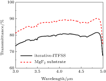
To measure the transmittance of the iterative ITFSS sample in the infrared band of 3– 5 μ m, a Fourier transform infrared spectrometer (Spectrum Gx, Perkin Elmer Corporation) was used in our experiment. The measurement results of the iterative ITFSS sample and MgF2 substrate are shown in Fig. 3. An average transmittance of 80% is obtained in the sample, which is higher than 76% in the standard ITFSS.[9] The higher transmittance may be attributed to the higher obscuration ratio in the iterative ITFSS, which indicates the fraction of the area without metal.[13] By removing the influence of MgF2 substrate to the sample transmittance, we can obtain that the transmittance of the separate iterative ITFSS structure is about 90%.
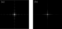
Furthermore, another significant feature for the ITFSS is the diffractive characteristics. When the ITFSS works for an imaging application, it will produce some diffracted orders, behaving as a diffractive grating in the infrared band. Only the zero-order diffractive light is useful for imaging and the other higher-order diffractive light will cause the stray light and degrade the imaging quality.[14] Therefore, the lower intensity of higher-order diffractive light is more desirable for an ITFSS. The diffractive characteristics of the iterative ITFSS and standard ITFSS are theoretically simulated by Fourier transformation of these pupil functions, as described before.[9] Figure 4 shows the simulation results. It can be easily found that the intensity of higher-order diffractive light is lower in the iterative ITFSS, which indicates that there will be less stray light and better imaging quality.
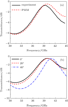
The transmittance response of the iterative ITFSS sample in millimeter wave band was measured by putting the sample on a bench between two lens antennas connected to the network analyzer (Agilent N5244A) in a dark room. The experimental result for the normal incident TE wave is shown in Fig. 5(a). It can be seen that a band-pass effect at the resonance frequency of 39.4 GHz is achieved. The transmittance is about − 0.74 dB and the bandwidth is 6.2 GHz. A simulation result based on the period method of moments (PMM)[15, 16] is also presented in Fig. 5(a). Good agreement between the experimental and simulation results indicates that we can design the iterative ITFSS for specific application and also predict its band-pass performance. Moreover, to verify the stability of the iterative ITFSS, we simulate the transmittance responses for different incident angles as shown in Fig. 5(b). It can be found that when the incident angle increases from 0° to 20° , the transmittance response is almost constant. When the angle increases to 40° , the resonance frequency just has a little shift from 40 GHz to 41 GHz, and the transmittance changes little, which can approve the iterative ITFSS stability. However, the PMM always needs plenty of computing time (e.g., two or three days) and places harsh demands on the computer hardware, which reduces the work efficiency.
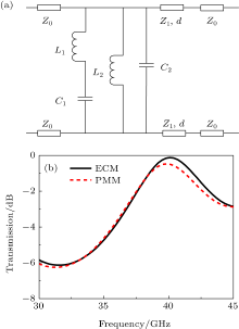
To overcome this problem, the equivalent circuit method (ECM) is attempted here for the iterative ITFSS, which has been proved as a convenient and quick way to calculate the transmittance response of FSS.[17, 18, 19] On the basis of the physical structure of iterative ITFSS, we establish the equivalent circuit model as shown in Fig. 6(a), in which Z0 is the free space impedance (Z0 = 377 Ω ) and Z1, which equals 
 | Fig. 5. (a) Experimental and simulation results of the transmittance response for the normal incident wave. (b) Simulation results for different incident angles. |
In conclusion, we have demonstrated a new ITFSS based on iterative metallic meshes, which is composed of two square metallic meshes with a misplaced overlap. Compared with the standard ITFSS, a higher transmittance of 80%in the infrared band of 3– 5 μ m is obtained experimentally and the theoretical simulations show that the iterative ITFSS produces a lower intensity of high-order diffractive light which is more desirable for imaging quality. In the millimeter wave band, the iterative ITFSS has a transmittance of − 0.74 dB at the resonance frequency of 39.4 GHz, and the bandwidth is about 6.2 GHz. Moreover, two methods (ECM and PMM) are combined to analyze the transmittance response of the iterative ITFSS, which can be quite useful in the practical design process. We believe that the iterative ITFSS will be an efficient way to realize a metamaterial millimeter wave/infrared film.
| 1 |
|
| 2 |
|
| 3 |
|
| 4 |
|
| 5 |
|
| 6 |
|
| 7 |
|
| 8 |
|
| 9 |
|
| 10 |
|
| 11 |
|
| 12 |
|
| 13 |
|
| 14 |
|
| 15 |
|
| 16 |
|
| 17 |
|
| 18 |
|
| 19 |
|


