Spin transport properties of a Dresselhaus-polygonal quantum ring*
[Tang Han-Zhaoa) , Zhai Li-Xuea) , Shen Mana), b)†  , Liu Jian-Jun
a), c)‡ ]
, Liu Jian-Jun]
|
|


†Corresponding author. E-mail: shenman@semi.ac.cn
‡Corresponding author. E-mail: liujj@mail.hebtu.edu.cn
*Project supported by the National Natural Science Foundation of China (Grant No. 61176089), the Natural Science Foundation of Hebei Province, China (Grant No. A2011205092), and the Foundation of Shijiazhuang University, China (Grant No. XJPT002).
We propose a theoretical method to investigate the effect of the Dresselhaus spin–orbit coupling (DSOC) on the spin transport properties of a regular polygonal quantum ring with an arbitrary number of segments. We find that the DSOC can break the time reversal symmetry of the spin conductance in a polygonal ring and that this property can be used to reverse the spin direction of electrons in the polygon with the result that a pure spin up or pure spin down conductance can be obtained by exchanging the source and the drain. When the DSOC is considered in a polygonal ring with Rashba spin–orbit coupling (RSOC) with symmetric attachment of the leads, the total conductance is independent of the number of segments when both of the two types of spin–orbit coupling (SOC) have the same value. However, the interaction of the two types of SOC results in an anisotropic and shape-dependent conductance in a polygonal ring with asymmetric attachment of the leads. The method we proposed to solve for the spin conductance of a polygon can be generalized to the circular model.
In recent years, much attention has been paid to spintronics especially the transport properties of low dimensional with spin– orbit coupling (SOC).[1– 4] In semiconductor heterojunctions, the SOC can be generated by two mechanisms. The Rashba SOC (RSOC) is due to structure inversion asymmetry, [5, 6] and can be controlled by an external electric field. The Dresselhaus SOC (DSOC), on the other hand, is caused by bulk inversion asymmetry, and is a property of the materials used.[7– 9] The DSOC has been studied both theoretically and experimentally in conventional semiconductor devices, [7– 10] and can be used to manipulate the spin direction of electrons in semiconductors.
Due to their special construction, considerable attention has been paid to investigating novel quantum interference effects in quantum rings, and quantum ring models have been manufactured on AlGaAs/GaAs heterostructures by Fuhrer et al.[11] The magnetotransport properties of a circular quantum ring subject to the DSOC have been discussed by Wang et al.[10] Sheng et al.[13] have studied the spin state of electrons, the persistent charge current and the spin current in circular quantum rings with DSOC. They found that the projectional vectors of the local spin orientations vary in a ring and the cylindrical symmetry is broken due to the DSOC. Beyond the work on circular ring models, [11– 14] polygonal ring models with only RSOC have been reported in several studies.[15– 22] Nevertheless, to the best of our knowledge, the effects of the DSOC on the spin transport in a polygonal ring have not been discussed, and it is now important to ask whether the time reversal symmetry (TRS) of the spin conductance of a polygon can be broken by the DSOC. It is also necessary to determine whether DSOC induces an anisotropic conductance and a shape-dependent conductance in a polygonal ring with RSOC. To answer these questions, in this paper, we propose a method to investigate the effect of DSOC on the spin transport properties of a polygon. The method we have proposed can be generalized to a circular model.
The paper is organized as follows. The conductance of a regular polygon with an arbitrary number of segments subject to the DSOC is solved analytically in Section 2. The results and analyses of the spin conductance and an anisotropic conductance are shown in Section 3. Finally, we give a summary in Section 4.
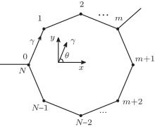
A polygonal quantum ring coupled with an input lead at vertex 0 and an output lead at vertex m is shown in Fig. 1. Only the polygon is subjected to SOC. The segments under consideration are taken to be single-channel ballistic quantum wires.[23] Initially, we consider a two-dimensional electron gas (2DEG) model with DSOC. The Hamiltonian operator in the x– y plane can then be written as[13]

where

and m* is the effective mass. kD is the strength of the DSOC. The energy can be obtained as

when a two-dimensional (2D) plane wave function is used in Eq. (1). For a particular 1D quantum wire lying in the γ direction, we set the relative coordinate system along the direction of that segment (see Fig. 1), and then simplify the form of the Hamiltonian operator for that segment. Then,

in which kγ is the wave vector along the γ direction, n = (cosθ , − sinθ , 0) and σ represents the Pauli matrices. We can obtain the wave function of any segment in the polygon by solving Eq. (2). The wave functions at the input lead (ψ in) and output lead (ψ out) are

where A, B, and C are the injection, reflection, and transmission spinors respectively. We use the same method as in Ref. [18] to connect the wave functions of the individual segments. The transfer matrix Tn, n– 1 can be obtained as
where 
where
Finally, the spin conductance of a polygonal quantum ring can be obtained using the Landauer– Bü ttiker conductance formula[24, 25]
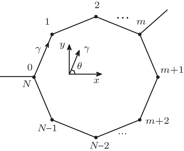 | Fig. 1. A one-dimensional (1D) regular polygonal quantum ring with N segments. |
The spin-dependent conductances, G↑ and G↓ , and Gtotal obtained using Eqs. (4) and (5) are shown in Fig. 2 for the case of a hexagon. We use G0→ m to describe the conductance of a polygon with the input lead located at vertex 0 and the output lead located at vertex m, while Gm→ 0 is for the case with the input and output leads reversed. We first focus on the effect of the DSOC on a regular polygonal quantum ring. In our calculations, the spin-dependent conductance is invariant under an increase in the number of segments. This implies that the spin conductance for a polygon can describe the results for a circular ring with only the DSOC.
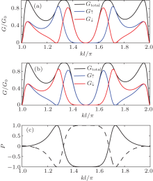
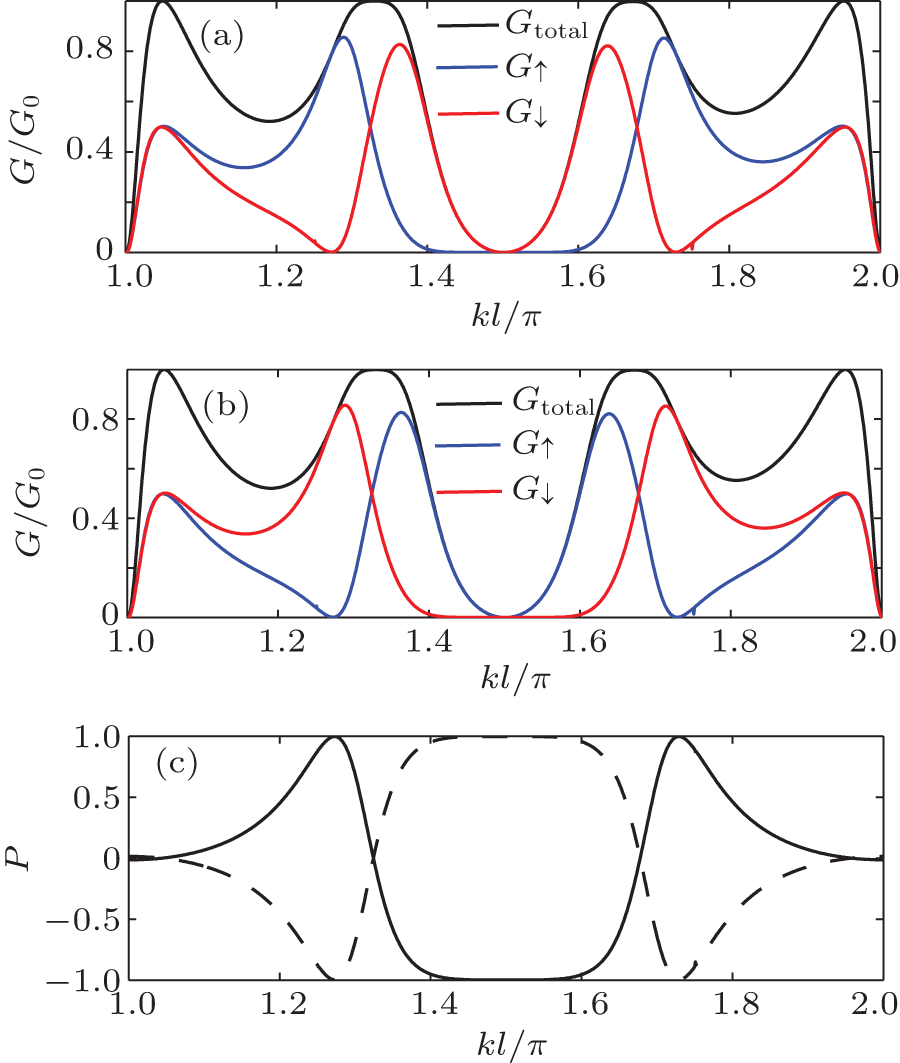 | Fig. 2. Spin dependent conductances for unpolarized incident electrons: (a) G0→ m, (b) Gm→ 0, and (c) the polarization for G0→ m (solid line) and Gm→ 0 (dashed line) in a hexagon versus the value of the wave vector kl with m = 2 and kDl = 0.45π . |
The spin-dependent conductances for the case where only the DSOC is considered and the injected electrons are unpolarized are illustrated in Fig. 2. The SOC is the result of the torque of the external electrical field on a moving spin in the system with the result that the spin precesses as the electron transmits along the segment.[26, 27] The conductance thus becomes polarized. In addition, comparing Fig. 2(a) with Fig. 2(b), it is interesting to note that the total conductances of a polygon subject to DSOC for the 0→ m case and the m→ 0 case have the same value, but the spin conductances G↑ and G↓ do not. That is different from the case of a polygonal ring subjected to RSOC alone.[18] Comparing the second term of the Hamiltonian operator in Eq. (2), ħ 2kDkγ σ · n/m* , with the Zeeman energy term μ B· σ , [14] it may be seen that the effects of the DSOC are, in fact, like an effective magnetic field, the effective magnetic field being BD = ħ 2kDkγ n/(μ m* ). When only the DSOC is considered, the direction of the effective magnetic field is (cosθ , − sinθ , 0), which is x axis axisymmetric with the direction of segment γ = (cosθ , sinθ , 0). This is different from the Rashba effect. The projectional vectors of local spin orientations do not point to the center of the system in the polygon subjected to the DSOC, and consequently, the cylindrical symmetry of the projectional vectors of the local spin orientations is lost.[13] Therefore, our results show that the effect of the DSOC can destroy the TRS of the spin conductance but not that of the total conductance. The phase locking effect[28– 31] is broken and spin polarized conductances appear because of the spin-dependent phase induced by the DSOC and because of the interference of the spin up and spin down electrons tunneling in the upper and lower arms.
Based on the properties of the DSOC, a method to generate and control the spin polarized conductance can be proposed by using a polygon subjected to only the DSOC. We can use a polygonal quantum ring to filter electrons by their spin direction. For the 0→ m case, shown in Fig. 2(a), there is a range of kl with zero conductance for spin up electrons over the interval 1.4π < kl < 1.6π while the conductance for spin down over the same interval is non-zero except near kl = 1.5π . However, for the m→ 0 case shown in Fig. 2(b), there is a similar range with zero conductance for spin down electrons over the interval 1.4π < kl < 1.6π and a finite conductance for spin up over the same interval except near kl = 1.5π .
To better compare the results shown in Figs. 2(a) and 2(b), we introduce the polarization using

In Fig. 2(c), we can see that the electrons, flowing from the vertex 0 and through the two different paths, the upper arm (from node 0 to node m) and the lower arm (from node N to node m), around the polygon to the vertex m, are pure spin down for 1.4π < kl < 1.6π when kDl = 0.45π . If we reverse the input and output leads, the electrons, flowing from the vertex m and through the two different paths to the vertex 0, are pure spin up for 1.4π < kl < 1.6π . We get a range of P = 1 polarization for the 0→ m case and a range with P = − 1 polarization platform for the m→ 0 case with the same strength of the DSOC. The spin-dependent phase is different for electrons transmitted in the upper arm (from node 0 to node m) and the lower arm (from node N to node m). We can say that the polarized conductance is caused by the extra spin-dependent phase induced by the DSOC. Therefore, we can use this result to design a spin filter and get a pure spin of either sign based on a polygonal quantum ring with only DSOC by the simple method of exchanging the source and the drain.
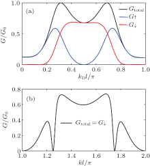
Next, the conductances of a polygonal ring are shown in Fig. 3 when the incident electrons are polarized. Figure 3(a) shows the spin-dependent conductances versus the strength of the DSOC for the case where the spin direction of the incident electron is up. The transmitted electrons are all spin up when the strength of the DSOC is zero; kD = 0. However, the transmitted electrons are all spin down when kDl = 0.5π . The spin-dependent conductances versus the wave vector kl are plotted in Fig. 3(b) for the case kDl = 0.5π . We note that the transmitted electrons are all spin down and the spin down conductance has peaks at kl = 1.3π and kl = 1.7π when the incoming electrons are all spin up. In our calculation, if we exchange the source and the drain when the incident electrons are all spin down, the transmitted electrons are all spin up for the same DSOC strength. This unique spin flip phenomenon is due to two factors. One is the spin precession induced by the DSOC; the other is that the TRS is broken by the DSOC. Therefore, for the polygonal quantum ring under consideration, given a suitable strength of the DSOC, the electron spin direction can be reversed. This model is more effective than a polygon with only the RSOC.[18]
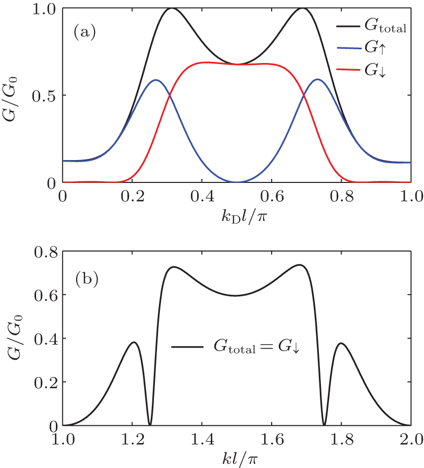 | Fig. 3. Spin-dependent conductances G0→ m in a square (N = 4 and m = 1) when the incident electrons are polarized spin-up, shown in panel (a) as a function of kDl with kl = 3.4π and in panel (b) as a function of the wave vector kl with kDl = 0.5π . |
In this part, we concentrate on the effect of the DSOC on a polygonal quantum ring, which is also subject to the RSOC (kR is the strength of the RSOC). When both types of SOC are considered, the Hamilton becomes

and energy can be obtained as

where

is the effective strength of the SOC, θ is the angle between k and the x axis and

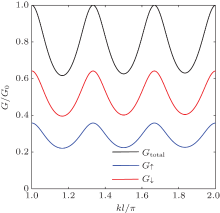
Initially, we focus on the spin conductance in a symmetric regular polygonal ring (m = N/2). The spin dependent conductances of a symmetric hexagon are shown in Fig. 4 for the case kRl = kDl = 0.2π . The spin direction of the electrons in a polygon can be controlled by both types of SOC. However, the total conductance oscillates from 0.64 to 1 in our model which is the same as for the circular model without SOC, as can be seen in Fig. 2 in Ref. [12]. When a symmetric polygonal ring with both types of SOC, both with the same value, is considered, the total conductance is

where
Our calculations show that the total conductance of a polygonal quantum ring depends only on the length of the perimeter (Nl) of the polygon. However, the total conductance of a polygon cannot be controlled by the strength of the SOC and the number of the segments in a polygon under these conditions. This result provides a method to measure the strength of the DSOC using the RSOC, which can be conveniently and precisely controlled using a vertical electric field.
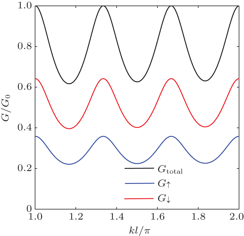 | Fig. 4. Spin-dependent conductances of a hexagon with kRl = kDl = 0.2π when m = 3. |
Next, we study the spin conductance in a polygonal ring with asymmetric attachment of the leads (m ≠ N/2). To make our results clearer, we introduce the concept of the strength of the anisotropic conductance

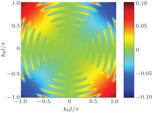
The strength of the anisotropic conductance as a function of the strength of the DSOC and the RSOC is illustrated in Fig. 5. We can see that the strength of the anisotropic conductance is 0 when kRl = 0 or kDl = 0. The anisotropic conductance shows an oscillation with the strength of the SOCs, and the maximum of the anisotropic conductance can reach as high as 0.1. According to the results of Fig. 2 and Ref. [18], the total conductance in a polygonal quantum ring satisfies the conservation of TRS when the ring is subjected to only one of RSOC or DSOC. However, the time reversal invariance for the total conductance can be broken when a polygon is subjected to both the RSOC and the DSOC. We can note that the energy, E, of the electrons in a polygon has a direction-dependent term 
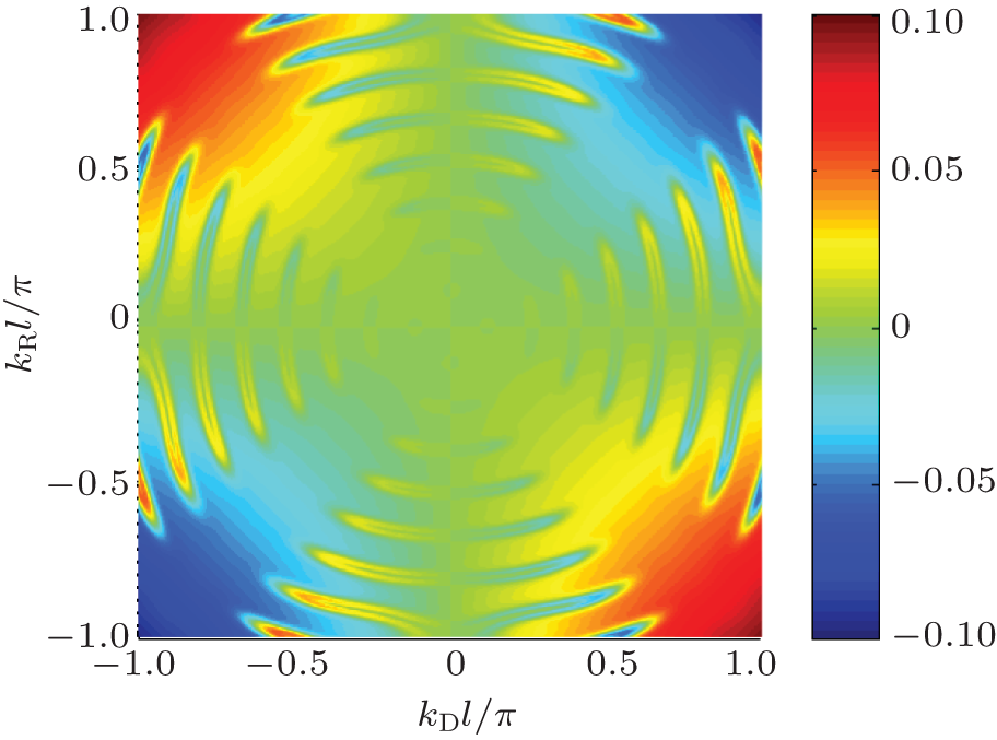 | Fig. 5. The anisotropic conductance of a polygonal ring N = 15 and m = 6 when kl = 3.4π . |
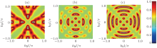
Figure 6 shows the conductance of three asymmetric polygonal quantum rings versus the strengths of the DSOC and the RSOC. The oscillations of the conductances are periodic with the strengths of the RSOC or the DSOC, and the pattern of the conductance is symmetric with respect to the lines kRl = ± kDl. The symmetry of the conductance is due to the fact that the status of the two types of SOC is equivalent in the Hamiltonian operator. Due to the combined effect of the two SOCs, the conductance of a polygonal quantum ring depends on the number of segments, which is very different from the conductance of a polygon with only the DSOC. With an increase in the number of the segments, the polygon approximates a circle and, in fact, the conductance of a pentadecagon is similar to the result of the circular model.[32, 33] Therefore, our method can solve the spin conductance of a polygon with an arbitrary number of segments, and this method can be generalized to the circular model. In a realistic model, Koga et al.[34] have present an experiment based on In0.52Al0.48As/In0.53Ga0.47As/In0.52Al0.48As quantum wells for designing a spin interferometer based on the polygonal rings. The RSOC can be controlled by an external electric field. The strength of the DSOC is proportional to d, where d is the thickness of the quantum well. We would like to stress that the effect of DSOC on the electrons transport in regular polygonal quantum rings is within the reach of today’ s technology.[34]
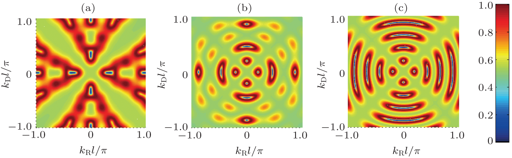 | Fig. 6. Dependence of the conductance of a regular (a) triangle, (b) hexagon and (c) pentadecagon on the strengths of the RSOC, kRl, and DSOC, kDl, SOCs when m = 1/3N and kl = 3.2π . |
In this paper, we have studied the effect of the DSOC on the spin transport properties of a regular polygonal quantum ring with an arbitrary number of segments. The conductance in our system was solved analytically and the method we have proposed can be generalized to the circular model. When the DSOC is considered in a polygonal ring, it is found that when the source and drain are exchanged, the behavior of the spin up conductance becomes that of the spin down conductance and vice versa. Using this unique property, we can obtain a pure spin up or spin down conductance very conveniently by exchanging the source and the drain. When the DSOC and RSOC are considered together in a polygonal ring with symmetric attachment of the leads, the total conductance is independent of the number of segments and the strength of the SOC when the two SOCs have the same value. For an asymmetric polygonal ring, however, an anisotropic conductance can be generated and the TRS is broken due to the interaction between the DSOC and the RSOC, and the conductance thus depends on the number of segments.
| 1 |
|
| 2 |
|
| 3 |
|
| 4 |
|
| 5 |
|
| 6 |
|
| 7 |
|
| 8 |
|
| 9 |
|
| 10 |
|
| 11 |
|
| 12 |
|
| 13 |
|
| 14 |
|
| 15 |
|
| 16 |
|
| 17 |
|
| 18 |
|
| 19 |
|
| 20 |
|
| 21 |
|
| 22 |
|
| 23 |
|
| 24 |
|
| 25 |
|
| 26 |
|
| 27 |
|
| 28 |
|
| 29 |
|
| 30 |
|
| 31 |
|
| 32 |
|
| 33 |
|
| 34 |
|