Corresponding author. E-mail: tom.yan@gmail.com
Projected supported by the National High Technology Research and Development Program of China (Grant No. 2012AA011603) and the National Natural Science Foundation of China (Grant No. 61372172).
The projection matrix model is used to describe the physical relationship between reconstructed object and projection. Such a model has a strong influence on projection and backprojection, two vital operations in iterative computed tomographic reconstruction. The distance-driven model (DDM) is a state-of-the-art technology that simulates forward and back projections. This model has a low computational complexity and a relatively high spatial resolution; however, it includes only a few methods in a parallel operation with a matched model scheme. This study introduces a fast and parallelizable algorithm to improve the traditional DDM for computing the parallel projection and backprojection operations. Our proposed model has been implemented on a GPU (graphic processing unit) platform and has achieved satisfactory computational efficiency with no approximation. The runtime for the projection and backprojection operations with our model is approximately 4.5 s and 10.5 s per loop, respectively, with an image size of 256×256×256 and 360 projections with a size of 512×512. We compare several general algorithms that have been proposed for maximizing GPU efficiency by using the unmatched projection/backprojection models in a parallel computation. The imaging resolution is not sacrificed and remains accurate during computed tomographic reconstruction.
Computed tomographic (CT) reconstructions of three-dimensional (3D) objects reconstructed from a set of integrals from projection data are becoming increasingly popular. CT has the advantages of high efficiency, fast scanning speed, flexible scanning scope, and high image resolution. Iterative reconstruction methods[1– 6] have attracted considerable interest in recent years because they can cope well with limited projection sets and noisy data. However, these methods demand huge computational cost.[1, 2] In iterative reconstruction, projection and backprojection as two vital operations are repeated per iteration and are time-consuming in reconstruction processing.
In iterative reconstruction algorithms, the projection and backprojection procedures for a discrete imaging object have been modeled. Different types of system matrix models have been studied for weighing the relationship between discrete projection data and discrete reconstructed object. These models compromise computational complexity and accuracy. Numerous approaches have been proposed to express system matrix coefficients. Conventional models can be classified into the following categories:[7] intersection length model, [8] linear interpolation model, [9, 10] distance– distance model, [11] basis function model, [12] finite beam width model, [13] and Fourier-based projection model.[14] Simple models, such as intersection length and linear interpolation models, are often applied in computed iterative reconstruction because of their computing convenience. In addition, these models can be used for high-frequency artifacts. Exact models, such as basic function and finite beam width models, can hardly be used for computed iterative tomography, particularly in 3D reconstruction, because they suffer from computational inefficiency.
For implementing the projection and backprojection operations in 3D reconstruction, the corresponding sparse matrix-vector multiplication (SpMV)[15] method based on compressing matrices can be used given that the system matrix is sparse. However, SpMV only adapts to a limited scale. The calculation of the system matrix coefficients usually needs to be repeated and the computing effect usually needs to be sacrificed to change for the need of hardware source. In recent years, high-performance computation using programmable commodity hardware has been a useful tool in medical imaging. Particularly, GPUs offer an attractive alternative platform to cope with the demands in CT for the high peak performance, cost effectiveness, and availability of a user-friendly programming environment.[15] The methods for realizing the projection and backprojection operations are usually classified into two categories, namely, ray-driven[8] and voxel-driven methods.[16] In the voxel-driven method, the detectors are updated with voxel values using similar weights in the projection process. In the ray-driven method, the voxels are updated with detector values. However, in the reconstruction implementation, unmatched projector– back projector pairs are often used for GPU-accelerated methods to cater for the approximation need and to maximize the efficiency of GPUs. These projectors include ray-driven and pixel-driven back projectors. It can cause additional artifacts in reconstruction, which propagate through iterations and decrease reconstruction accuracy, particularly when the number of iterations is increased.[17]
This study introduces a new fast parallel alogrithm for a 3D distance-driven model (DDM) in cone-beam CT (CBCT) reconstruction. The method has the advantage of the distance-driven model with a low arithmetic cost and good approximation to the true strip integral compared with general models, such as the intersection length model or linear interpolation model. The method can be fit for parallel computing and either the projection onto a given detector cell or the back-projection onto a given voxel has been calculated and updated per independent thread on a GPU platform. This method significantly improves the computational efficiency, and the result is similar to the non-accelerated model. Our method provides a matched projector– backprojector pair, and the system matrix of projection is the adjoint of backprojection matrix. Compared with other GPU-accelerated methods with unmatched projector– backprojector pair, our method provides a more accurate performance in image reconstruction.
CT scanners can be modeled using several imaging systems by the following linear equation

where p ∈ P represents projection data, f ∈ F represents a pre-reconstructed image, and the system matrix W : F → P is a projection operator. In practice, the discrete– discrete model is assumed. For the 3D case, an image f can be discretized by adding a cube grid on the image, and the projection data p are usually measured with detector cells. As a result, we develop a 3D image f = (fi, j, k) ∈ RNx × RNy × RNz, where the indices 1 ≤ i ≤ Nx, 1 ≤ j ≤ Ny, 1 ≤ k ≤ Nz are integers. The geometry of the x-ray imaging system in CBCT can be illustrated as shown in Fig. 1.
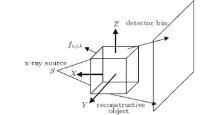 | Fig. 1. The geometry of the x-ray imaging system. S represents the x-ray source, and fi, j, k represents the 3D reconstructed object. |
In CBCT, equation (1) can be rewritten as

where fi, j, k is the underlying source voxel, pm, θ is the projection measured in the m-th finite-width detector cell at angle θ , and Wmθ , ijk ≥ 0 denotes the element of the system matrix. Equation (2) can also be regarded as the general expression of the projection. The system coefficient Wmθ , ijk weighs the contribution of voxel fi, j, k to the m-th detector cell at angle θ . The discrete– discrete model of backprojection operation can be homoplastically expressed by

In this study, we develop parallel computing methods that can rapidly compute the projection and backprojection operations on the fly.
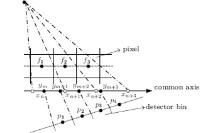
In two-dimensional (2D) DDMs, both pixel and detector boundaries are mapped onto a common axis, and overlapped areas can be normalized and approximated as the system matrix coefficient (Fig. 2). The 2D image pixels are fi (i = 1, 2, 3) and the detector bins are pi (i = 1, 2, 3). Both the pixel boundaries and the detector bin boundaries are mapped on a common axis and the coordinates of pixel projection points are xn, xn+ 1, xn+ 2, xn+ 3 while the ym, ym+ 1, ym+ 2, ym+ 3 represent the coordinates of detector bins projection points. For example, the forward projection value of the detector bin p2 can be calculated as

and the backprojection value of the pixel f2 can be shown as

Nguyen et al.[18] designed a novel scheme to solve the 2D DDM for parallel computation. In the study, the forward projection and backprojection operations can be realized on GPUs. These operations do not cause “ writing conflict.” The key for the algorithm is to utilize the detector and pixel boundaries to find a set of pixels and detector bins, respectively. They also explained that their method can be extended to the improved distance-driven method called the separate footprint method.[19]
De Man and Basu[20] introduced the 3D method. In the 3D DDM, the horizontal and vertical boundaries of the image voxels and detector cells are mapped onto a common plane, and the overlap lengths along the horizontal and vertical directions are calculated, respectively. Then, the overlap area is obtained by multiplying the two lengths. This method approximates the shape of a rectangle and simplifies the calculation.
For the traditional sequential processing for both projection and backprojection, the efficient method is to map all the voxel boundaries and the detector cells boundaries in a 3D image slice onto a common plane along the horizontal and vertical directions separately and then to sequentially compute the two normalized overlap lengths between the voxels and detector bins by using the intersections on the common plane. Whereas, this scheme is not optimal for parallel computing, because computing the normalized length each time along the common plane updates many detector bins in projection and many voxels in backprojection. In this study, we proposed a fast parallel algorithm to solve the parallel computing for the 3D distance-model in the forward projection and backprojection.
In this study, we consider a 3D image that consists of (Nx, Ny, Nz) voxels with a size of (dx, dy, dz). Let Nx = Ny, dx = dy = dz = 1 and the center point of the image at the origin is defined. We also define that fi, j, k represents the voxels of the reconstructed object and (x, y, z) is the location coordinates, and i, j, k are the voxel indices.
Moreover, we define that the detector consists of (Ns, Nt) pixels with a size of (ds, dt). The horizontal and vertical boundaries of the detector cell are mapped onto the x– z plane (or the y– z plane) and the x– y plane of every voxel slice as the common plane between detector cells and voxels. We consider that the coordinate of the source focal point is S(x1, y1, z1) and that the coordinate of the center of the detector cell is det(x2, y2, z2). The coordinates of the four boundary points are (x2 + dssinθ /2, y2 − dsconθ /2, z2), (x2 − dssinθ /2, y2 + dsconθ /2, z2), (x2, y2, z2+ dt/2), and (x2, y2, z2− dt/2). The angle θ is the rotation angle.
Then we need to compute for the slope of the connecting line between the center of the detector cell and the source focal point and decide which plane would be chosen to divide the 3D image. When | x2− x1| > | y2− y1| , we divide the 3D image by the y− z plane as shown in Figs. 3(a)– 3(d). When | x2 − x1| ≤ | y2 − y1| , the x− z plane is selected to divide the image. When | x2 − x1| > | y2 − y1| , every detector cell has four beams connected to the focal point, and all beams intersect each y− z plane. We then need to compute the intersection coordinates and indices of the four beams for the i-th y− z plane. The y-coordinates of the intersections of the two beams in the horizontal direction can be calculated as follows:

with

and then we obtain the largest integers that are smaller than yi1 and yi2, i.e.,

which are exactly the y-indices of the intersecting voxel candidates. Similarly, we can calculate the z-coordinates of intersections of the two beams in the vertical direction as follows:

with

and then obtain the largest integers that are smaller than zi1 and zi2, i.e.,

which are exactly the z-indices of the intersecting voxel candidates. We then only deal with 3D forward projection as 2D cases.
The key of this proposed algorithm is to observe that the intersections are classified into only two cases for both the y direction and the z direction because of the fact that the size of the detector cell is usually smaller than or equal to the size of voxel. One is the two intersections in the voxel, and the other is the only intersection in the voxel. Consequently, the four beams of one detector cell intersect with the voxels in each slice of the image with at most four cases (Fig. 3).
If Yi1 = Yi2, Zi1 = Zi2 (Fig. 3(a)), only one voxel in the i-th slice contributes to the detector cell, and the weight can be calculated as follows:

If Yi1 ≠ Yi2, Zi1 = Zi2 (Fig. 3(b)), two voxels in the i-th slice in the horizontal direction contribute to the detector cell, and the weights of two intersecting voxels can be calculated as follows:

If Yi1 = Yi2, Zi1 ≠ Zi2 (Fig. 3(c)), two voxels in the i-th slice in the horizontal direction contributes to the detector cell, and the weights of two intersecting voxels can be calculated as follows:

If Yi1 ≠ Yi2, Zi1 ≠ Zi2 (Fig. 3(d)), four voxels in the i-th slice contribute to the detector cell, and the indices and weights of four intersecting voxels can be calculated as follows:
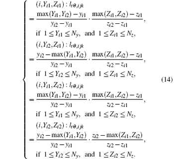
It should be noted that the detector in our text is flat and the weight coefficient calculated should be multiplied by the factors as mentioned in De Man’ s paper.[21] The factors can be pre-calculated before the intersection weight coefficient, using the in- and out-of-plane angles of the line of interest with the axis perpendicular to the slab of detector bins.
The proposed 3D algorithm is easy to implement for both central processing units (CPUs) and GPUs. For the parallel computing version in the GPUs, we can consider computing the intersections of the beams of one detector cell per parallel thread. Our method for calculating the weight coefficients is less complex than the method for calculating the intersection lengths of beams with each voxel of the 3D image.
The backprojection essence is the adjoint transformation of the forward projection. For parallel computation, we consider that the main loop is the indices of the image voxels and that the weight of each voxel can be calculated per parallel thread. During the implementation, the detector cells that contribute to the voxel in the shadow region must be identified. For the notations, we define (xa, ya, za) as the coordinate of the center of the voxel, (Na, Nb) as the number of the detectors along the y and z directions, SO as the distance from the source to the detection line, SD as the distance from the source to the detection line, dy as the detector cell width, and ϕ as the scan angle.
To simplify the calculation for finding the contributing detector bins, Gao[22] proposed a fast method for calculating the contributing detectors in the shadow region when the voxel and scanning direction are given. In Gao’ s method, the range of contributing detector bins is extended through a rhombus enclosed in the circumscribed sphere of the voxel to simplify the coordinate calculation.
In our distance-driven backprojection method, the coordinates of the current voxel boundary points Bleft, Bbottom, Bright, and Btop are acquired after the coordinate system of the reconstructed volume is rotated with the detector being perpendicular to the coordinate axis. As a result, the new coordinates of the boundary points of the voxel are (xBleft, yBleft, zBleft), (xBright, yBright, zBright), (xBtop, yBtop, zBtop), (xBbottom, yBbottom, zBbottom) expressed as Eq. (15)
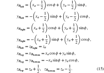
Four varying variables bl, bb, br, and bt that are projective coordinates of the current voxel project on the detector are shown in Fig. 4 and the coordinates are expressed as Eq. (15). Consequently, we can find the detector bound along the y- and z-directions through

 | Fig. 4. Four projective mappings Bleft, Bbottom, Bright, and Btop of the coordinates of the current voxel project on the detector corresponding to four varying variables bl, bb, br, and bt. |
After the contributing bins are acquired, which are often only a few, the backprojection weight coefficient of the given voxel with the contributing bins can be easily computed. Although the calculation is more complex in the backprojection to match the system matrix of projection, the algorithm can also achieve a good performance for the parallel computation.
To evaluate the performance of the Compute Unified Device Architecture (CUDA)-aided implementation, we implement and test the operation of forward projection and backprojections on both CPU and GPU. To verify our forward projection and backprojection implementations, we concentrate on the SART algorithm[23] that is classical in the algebraic reconstruction algorithms[21, 23, 24] to test the GPU-based DDM with simulated and physical experiments. Furthermore, two data sets are used for NVIDIA GPU architecture Tesla K20c. This GPU device has 2496 CUDA cores and 5120 MB global memory. In the performance test, a 3D Shepp-Logan phantom with an attenuation coefficient of 0.0 to 1.0 is utilized. A single circle trajectory is utilized for cone beam scanning. The source to axis distance is 30 cm, and the distance of the source to the center of the flat panel is 60 cm. The detector panel has a size of 12.8 cm × 12.8 cm, and the phantom has a size of 6.4 cm × 6.4 cm × 6.4 cm. The projection data are collected by 360 equally angular views in 360° .
Two types of discretization are applied to test the two operations under different data sets (Table 1). All experiments are performed on the workstation configured with dual cores Intel Xeon CPU of E5-2620 @ 2.10 GHz (only one core is used) and a NVIDIA GPU card of Tesla K20c. The time consumption for both CPU and different GPUs is listed in Table 2 together with the speedup. The time consumption is calculated through the statistical average of 50 iterations. The speedup in Table 2 shows that the acceleration strategy applied in this study can considerably improve the performance with GPU.
| Table 1. Dataset for situations 1 and 2. |
| Table 2. Running time for related operation in reconstruction (unit for time: seconds). |
To verify the reconstruction accuracy for both the CPU-based and GPU-based methods, we calculate the root-mean-square error (RMSE) of each reconstruction, which is obtained by

| Table 3. RMSE of GPU computation for related operation. |
In the simulation study, we only test the performance of our model with computing efficiency in the forward and backprojection, and in the next section we will test the performance of the model with both computing efficiency and imaging quality.
The reconstruction algorithm proposed in this study is composed of projection and backprojection, with a few vector additions and comparisons. In this sub-section, reconstruction is performed using both simulation data and real CT projections. The goal is to test the performance of the new model and the quality of image reconstruction. For real data reconstruction, the projections of a medical head phantom are acquired with the CBCT system, which mainly consists of a flat-panel detector (Varian4030E, USA) and an x-ray source (Hawkeye 130, Thales, France). Table 4 lists the scanning and reconstruction parameters. The result also proves that almost no difference exists between the RMSEs of the CPU-based and GPU-based reconstructions.
| Table 4. Parameters in a CBCT scan. |
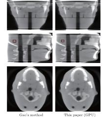
We perform an intersecting-line model and a DDM in iterative reconstruction with real data with SART. Although the system matrix model is significantly accurate with the intersecting-line length model, the ray-driven result also shows the interpolation artifacts (Fig. 4). The artifacts can be completely eliminated using DDM (Fig. 4). Compared with the ray-driven model in Gao’ s method, [22] our GPU-based DDM maintains the distance-model characteristics to prevent the high-frequency artifacts caused by the discretization of detector cells. As shown in Table 5, the experiment for real data verifies our proposed method for improving the computational efficiency and achieving a high acceleration ratio.
| Table 5. Running time for real data experiments of the SART algorithm with two models. |
To quantify the image quality of reconstructed images in terms of image noise, the signal to noise ratio (SNR) of a region of interest (ROI) is shown in Table 6. The calculation is as follows:

where p is the set of pixels inside the ROI and stands for a spatial average over the ROI. It can be observed from Table 6 that the SNR of images reconstructed by our method is higher than Gao’ s method and it could indicate our method has the advantage of suppressing the noise.
| Table 6. SNR of the ROI for Gao’ s method and this method. |
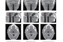
We perform additional reconstructions using the SART algorithm with two projector– backprojector pairs to compare the performance of our proposed methods with other methods. The experiments are prepared with the pair of ray-driven and voxel-driven backprojectors as well as the unmatched pair of distance-driven and backprojectors. The unmatched pair with ray-driven and voxel-driven backprojectors is generally used in the conventional GPU-based method. In this method, we consider the unmatched DD-PRJ/DD-BPR pair used in Daniel’ s study, [25] in which the backprojection operation is approximated to accelerate the computational speed. Figure 6 shows the performance of the three methods in real data reconstruction. This figure also illustrates a noticeable artifact caused by the unmatched projector/backprojector pair. The unmatched model accelerates the reconstruction computational efficiency but causes inaccurate results. In addition, this model affects the analysis and evaluation of the reconstructed real image. Table 7 shows the SNR of three methods in the performance of imaging reconstruction. It also can prove that our method has the better performance quality in the reconstruction.
| Table 7. SNR of the ROI for three contrast methods. |
We developed a fast parallel algorithm for the 3D distance-driven model which is known as an accurate and low-computational complexity projection and backprojection model. Our algorithm results in a matched projector– back-projector frame through the highly effective parallelization of both forward and backprojections. The key to our efficient algorithm is to exploit structure in the pattern of the cone beam rays, and decompose the problem into components in the slices of the 3D volume.
The simulation and real data experimental results show that the fast parallel GPU-based algorithm for the distance-driven model with respect to the optimized CPU-based method significantly accelerates the computational efficiency in iterative reconstruction. As expected, the reconstructed images using our GPU-based methods are identical to those using the conventional CPU-based methods. Compared with the other 3D projection and backprojection computational methods, such as the fast interacting-line length model, our proposed method has a better performance for balancing computational complexity and accuracy. In contrast to conventional GPU-accelerated models in which the reconstruction accuracy is often sacrificed for high-performance computation, our GPU-accelerated model can be guaranteed to maintain the accuracy with an accelerated system matrix model under a matched projector/backprojector frame.
In this study, we proposed a parallelizable algorithm for computing forward and backprojections. In the future, more optimization methods for CUDA or OpenCL can be used to optimize the parallel computation. The performance of the method can be tested in more iterative reconstruction algorithms, such as total variation regularization methods.
| 1 |
|
| 2 |
|
| 3 |
|
| 4 |
|
| 5 |
|
| 6 |
|
| 7 |
|
| 8 |
|
| 9 |
|
| 10 |
|
| 11 |
|
| 12 |
|
| 13 |
|
| 14 |
|
| 15 |
|
| 16 |
|
| 17 |
|
| 18 |
|
| 19 |
|
| 20 |
|
| 21 |
|
| 22 |
|
| 23 |
|
| 24 |
|
| 25 |
|


