Synthesis and microwave absorption properties of graphene–oxide(GO)/polyaniline nanocomposite with Fe3O4 particles*
Geng Xin, He Da-Wei†, Wang Yong-Sheng‡, Zhao Wen, Zhou Yi-Kang, Li Shu-Lei
Key Laboratory of Luminescence and Optical Information, Ministry of Education, Institute of Optoelectronic Technology, Beijing Jiaotong University, Beijing 100044, China

Corresponding author. E-mail: dwhe@bjtu.edu.cn

Corresponding author. E-mail: yshwang@bjtu.edu.cn

Project supported by the National Basic Research Program of China (Grant Nos. 2011CB932700 and 2011CB932703), the National Natural Science Foundation of China (Grant Nos. 61335006, 61378073, and 61077044), the Beijing Natural Science Foundation, China (Grant No. 4132031), and the Fundamental Research Funds for the Central Universities of Beijing Jiaotong University, China (Grant No. 2014YJS136).

Abstract

In order to investigate the impedance matching properties of microwave absorbers, the ternary nanocomposites of GO/PANI/Fe3O4 (GPF) are prepared via a two-step method, GO/PANI composites are synthesized by dilute polymerization in the presence of aniline monomer and GO, and GO/PANI/Fe3O4 is prepared via a co-precipitation method. The obtained nanocomposites are characterized by scanning electron microscopy (SEM), X-ray diffraction (XRD), and Fourier transform infrared spectroscopy (FTIR), respectively. The microwave absorbability reveals enhanced microwave absorption properties compared with GO, PANI, and GO/PANI. The maximum reflection loss of GO/PANI/Fe3O4 is up to −27 dB at 14 GHz with its thickness being 2 mm, and its absorption bandwidths exceeding −10 dB are more than 11.2 GHz with its thickness values being in the range from 1.5 mm–4 mm. It provides that GO/PANI/Fe3O4 can be used as an attractive candidate for microwave absorbers.

Keyword: 78.40.Me; 81.05.U–; polyaniline; graphene-oxide; Fe3O4; impedance matching; microwave absorption
1. Introduction

With the rapid development of aviation electronic technology, the microwave absorption technique has attracted national attention and gradually become one of the key technologies of modern research. In recent years, microwave absorbing material which possesses advantages such as tiny thickness, low density, strong absorption, and a wide absorption bandwidth has attracted more and more attention.[1] In addition, composite microwave absorption materials such as carbon nanotubes, dielectric/magnetic materials or conducting polymers, [2] have received increasing attention because of their enhanced microwave absorption properties, which are relevant to multiform reflection losses based on magnetic or dielectric loss.[3]

Recently, polyaniline (PANI) has been considered as one of the most promising conductive polymers in application fields such as biosensors, electromagnetic shielding, anticorrosion, electrode materials for secondary batteries, electrochromic devices, and membrane separations[4] due to its desirable electrical, electrochemical, and optical properties, and excellent environmental stability.[5] Graphene-based material has shown promising applications in nanoelectronics and energy storage recently. Owing to its high specific surface area and excellent conductivity, it can be used as a promising candidate for microwave absorbers. The preparation and application in microwave absorption of various nanocomposites containing graphene-based materials, conducting polymer or containing metal– oxide additives have been reported recently, such as PANI/graphene, [6] Fe3O4– graphene, [7] graphene– Fe, [8] carbon nanotubes/Fe, [9] reduced graphene oxide/Cu2O/Cu, [10] reduced graphene oxide– Co3O4, [11, 12] etc. However, the results indicate the microwave absorbing properties are not satisfactory. Therefore, the microwave absorbing materials must be designed so that their dielectric and magnetic properties vary with frequency precisely.[2]

In this research, we synthesize GO/PANI nanocomposite by using GO as a substrate to adsorb aniline monomer.[13] Nevertheless, GO and PANI are found to be non-magnetic, their microwave absorption properties are mostly contributed to dielectric loss.[14] So we add Fe3O4 particles to increase magnetic loss in order to achieve impedance matching. In our work, the maximum reflection loss of GO/PANI/Fe3O4 is up to − 27 dB at 14 GHz with its thickness being 2 mm and its absorption bandwidths exceeding − 10 dB are more than 11.2 GHz with its thickness values being in the range from 1.5 mm– 4 mm.

2. Experiment
2.1. Materials and composite preparation

All chemical reagents used in this study were analytical reagents and used without further purification. Aniline was distilled under the protection of high-purity N2 and then kept in a refrigerator before using. Graphene– oxide was synthesized from natural graphite oxidation using the modified Hummers method.[15]

2.2. Synthesis of GO/PANI(GP for short) nanocomposite

First, the purified GO (0.027 g) was added into 75 ml of 1 mol/L aqueous HCL solution, and the mixture was ultrasonicated until GO was fully dispersed. Afterward, 25-ml ethanol was added into the reaction solution to keep the solution from freezing. Then aniline monomer was added into the above solution. The mixture was stirred for 1 h at − 10 ° C to form a uniform mixture. The oxidant, (NH4)2S2O8 (APS), was dissolved in 25-ml aqueous HCL solution (the molar ratio of aniline to APS is 1.5) and the mixture was cooled to − 10 ° C. The polymerization was performed by the rapid addition of the precooled oxidant solution, and the mixture was stirred for 24 h at − 10 ° C. Emerald flocculent precipitates were obtained and washed with a large amount of 1-mol/L HCL, ethanol, and DI water. The resulting precipitates were diluted into 100-ml DI water. For comparison, PANI was synthesized in the absence of GO via the procedure mentioned above.

2.3. Synthesis of GO/PANI/Fe3O4 (GPF for short) nanocomposite

The 0.029-g Fe3O4 (synthetized by the titration hydrolyzation method) was added into 10-ml of ethanol and ultrasonicated until Fe3O4 was fully dispersed, then mixed with the prepared GO/PANI solution. After mechanical stirring for 24 h, the product was dried at 40 ° C for 48 h under a vacuum.

2.4. Characterization methods

The morphologies of the samples were characterized by scanning electron microscopy (SEM) (Hitachi S-4800), transmission electron microscopy (TEM) (JEM-1400 operating at 120 kV) and Fourier transform infrared spectroscopy (FTIR) (Thermo Fisher Nicolet 6700). The crystallographic structures of the samples were determined by X-ray diffraction (XRD) (BRUKER) equipped with Cu Kα radiation (k = 0.15406 nm). The electromagnetic (EM) parameters of the composite were measured by an HP8722ES network analyzer.

3. Results and discussion
3.1. Morphologies and microstructures of GP and GPF composite

Figure 1 shows the SEM images of GO, GP, and GPF nanocomposites. GO shows a paper-sheet-like shape. While GP nanocomposites exhibit multiple shapes, mainly flakes along with some fibrillar morphologies, and the sheets are thicker. Aniline monomers are adsorbed on the surfaces of GO flakes due to the electrostatic attraction.[13] With the polymerization reactions proceeding on the surfaces of GO flakes, the resulting nanocomposites display a flaky structure. PANI arrays are evenly covered on GO sheets, indicating that the nucleation and growth processes occur only on the surfaces of GO sheets. During the growth stage of PANI on the GO sheets, the linear nature and expanded chain structure of the PANI enable the PANI chains to act as a molecular template; [16] this structure could shorten the electronic conductive pathways. As shown in Fig. 1(c), Fe3O4 particles scatter on the surfaces of GO/PANI nanocomposites. These images above confirm that the ternary nanocomposites are synthesized successfully.

Fig. 1. SEM images of GO (a), GO/PANI (b), GPF (c) nanocomposites.

The XRD patterns of GO, GP, Fe3O4, and GPF nanocomposites are presented in Fig. 2. The XRD pattern of GO shows an intense, sharp peak that corresponds to the (0 0 1) plane at 2θ = 10.49° , corresponding to the interlayer spacing of 0.843 nm between GO sheets. In the case of GP, peaks at 9.4° , 14.5° , 20.5° , 25.3° corresponding to (0 0 1), (0 1 1), (0 2 0), and (2 0 0) crystal planes are the characteristic peaks of PANI in its emeraldine salt form, [17] while the characteristic diffraction peak of GO disappears, implying the full use of the GO in PANI as the substrate. In the case of Fe3O4, a series of diffraction peaks at 2θ = 30.4° , 35.9° , 43.4° , 53.5° , 57.6° , and 63.2° are attributed to the (2 2 0), (3 1 1), (4 0 0), (4 2 2), (5 1 1), and (4 4 0) reflections.[4] In the XRD pattern of GPF, the diffraction peaks of GP, the diffraction peaks of Fe3O4 particles can also be observed, indicating that the Fe3O4 particles exist in the nanocomposites.

Fig. 2. Typical XRD patterns of (a) Fe3O4, GP, GPF, and (b) GO.

The composite structure is further indicated by spectroscopic measurement. In the FTIR spectrum of GO, absorption peaks emerge at 1732 cm− 1, 1617 cm− 1, 1225 cm− 1, and 1053 cm− 1, corresponding to C= O characteristic absorptions in the – COOH, O– H flexural vibrations attributable to the vibrations of the residual water, C– OH stretching vibration and C– O stretching vibration, respectively, [18] which are consistent with previously reported results. In the spectrum of PGO shown in Fig. 3, absorption peaks centered at 792 cm− 1, 1121 cm− 1, 1290 cm− 1, 1482 cm− 1, and 1556 cm− 1 are attributed to the flexural vibrations inside and outside the aromatic C– H plane, C– N in PANI, the aromatic C= C stretching vibration, and the vibration of C= N respectively, [18] among which 1121 cm− 1 is the characteristic peak of conductive PANI. That the characteristic peaks of GO at 1732 cm− 1 and 1617 cm− 1 disappear proves not only that aniline monomers are polymerized by adsorption on the surface of GO, but also that the surface functional groups of GO participate in polymerization. It is possible that – COOH on the surface of GO, as a kind of proton doping agent, could be connected to N atoms in PANI.[19] In the case of GPF, all the characteristic peaks of PANI are found, proving that Fe3O4 particles are successfully dispersed into GO/PANI.

Fig. 3. FTIR spectra of pristine GO, PANI, GP, and GPF nanocomposite.

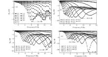
3.2. EM parameters and microwave absorbing properties of the nanocomposite

The reflectivity R is used to represent the microwave absorbing property. The reflection losses (RLs) of GO, PANI, PGO, and PGF each can be calculated from

In the above equations, ε r and μ r are the relative complex permittivity and permeability respectively, f is the microwave frequency, d is the layer thickness, and c is the velocity of microwave in free space.[7]

In Fig. 4(a), it can be observed that the maximum RL of GO is only − 3.4 dB at 9.3 GHz when its thickness is 5.5 mm. For PANI in Fig. 4(b), the maximum RL values are less than − 10.6 dB when the thickness values range from 0.5 mm to 5.5 mm. As shown in Fig. 4(c), the maximum RL of GO/PANI is − 14 dB at 15.8 GHz when the thickness is 5.5 mm. For GO/PNAI/Fe3O4 in Fig. 4(d), it is noted that there is one sharp and strong wave absorption peak at 14 GHz, the maximum RL is up to − 27 dB with its thickness being 2 mm, and the absorption bandwidths exceeding − 10 dB are more than 11.2 GHz (from 6.8 GHz to 18 GHz) with thickness values being in the range 1.5 mm– 4 mm. The results demonstrate that GO/PNAI/Fe3O4 exhibits excellent microwave absorption properties than . , and GN/Fe3O4.[7]

Fig. 4. Reflection loss curves of GO (a), PANI (b), GP (c), and GPF (d).

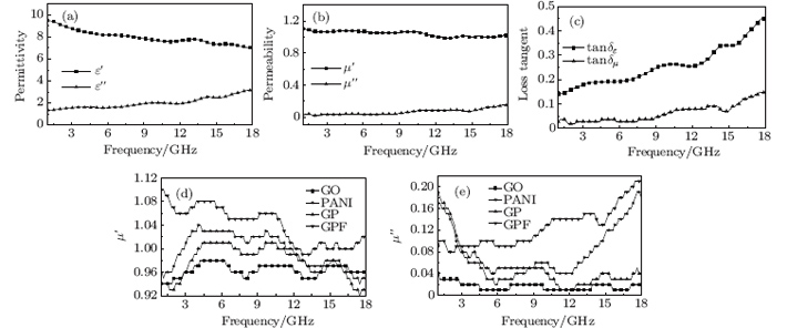
In order to investigate the possible microwave absorption mechanism of the composite sample, the values of complex permittivity real part (ε ′ ), permittivity imaginary part (ε ″ ), dielectric loss tangent (tanδ ε = ε ″ /ε ′ ), and magnetic loss tangent (tanδ μ = μ ″ /μ ′ ) of GO/PANI/Fe3O4 are shown in Figs. 5(a)– 5(c). We also investigate the permeability real part (μ ′ ) and imaginary part (μ ″ ) to compare the magnetic properties with those of GO, PANI, and GP, and they are shown in Fig. 5(d) and Fig. 5(e).

Fig. 5. Variations of complex relative permittivity (a), permeability (b), and the loss tangent (c) with frequency of GO/PANI/Fe3O4; comparisons of permeability real part (d) and imaginary part (e) among GO, PANI, GP, and GPF.

In Fig. 5(a), it is clear that the ε ′ decreases from 9.5 to 7.0 and the ε ″ increases from 1.35 to 3.2 with several fluctuations in the frequency range of 1 GHz– 18 GHz, which is due to electric dipolar polarization. This result suggests that the GO/PNAI/Fe3O4 composites have dielectric loss properties. In Fig. 5(b), the μ ′ values are in the range 1.0– 1.1 and the μ ″ values are less than 0.2 in the frequency range 1 GHz– 18 GHz. Moreover, from Fig. 5(c), it can be observed that tanδ μ and tanδ ε values each have a similar increase trend over the frequency range 1 GHz– 18 GHz and these tendencies are very close to each other, indicating an improved impedance matching. As is well known, the μ ′ and μ ″ show the ability to indicate the magnetic energy loss. It is noticed from Figs. 5(d) and 5(e) that the μ ′ and μ ″ of GPF are slightly higher than those of GO, PANI, and GP, indicating a better impedance matching between dielectric and magnetic loss.[20]

Firstly, the oxygen functional groups at the interface of GO and the interaction between π π * promote the adoption of aniline monomer, which is conducive to the transmission electron and the improvement of conductivity.[13] Secondly, GO and PANI are dielectric loss absorbers, [21, 22] and Fe3O4 particles are magnetic loss absorbers.[23] The enhanced impedance matching has a significant effect on improving the microwave absorption properties.[24] Thirdly, electronic spin and charge polarization play an important role in the microwave absorption properties due to the electronic transmission between Fe2+ and Fe3+ ions.[2]

4. Conclusion

In this paper, the ternary composites of GO/PANI/Fe3O4 are successfully prepared via a co-precipitation method. The obtained nanocomposite presents enhanced microwave absorption properties compared with GO, PANI, and GO/PANI. The maximum RL of GO/PANI/Fe3O4 is up to − 27 dB at 14 GHz with its thickness being 2 mm and the absorption bandwidths exceeding − 10 dB are more than 11.2 GHz with its thickness values being in the range 1.5 mm– 4 mm, which may be due to the better impedance matching. It indicates that GO/PANI/Fe3O4 could be a promising candidate as a new microwave absorption material with both strong absorption and a wide absorption bandwidth.

Reference
1 Wang Z, Bi H, Liu J, Sun T and Wu X 2008 J. Magn. Magn. Mater. 320 2132 DOI:10.1016/j.jmmm.2008.03.043 [Cited within:1] [JCR: 1.826]
2 Liu P, Huang Y and Zhang X 2014 J. Alloys Compd. 596 25 DOI:10.1016/j.jallcom.2014.01.188 [Cited within:3] [JCR: 2.39]
3 Ni S, Wang X, Zhou G, Yang F, Wang J and He D 2010 J. Alloys Compd. 489 252 DOI:10.1016/j.jallcom.2009.09.065 [Cited within:1] [JCR: 2.39]
4 Yang C, Li H, Xiong D and Cao Z 2009 Reactive and Functional Polymers 69 137 DOI:10.1016/j.reactfunctpolym.2008.12.008 [Cited within:2] [JCR: 2.505]
5 Imran S M, Kim Y, Shao G N, Hussain M, Choa Y H and Kim H T 2013 J. Mater. Sci. 49 1328 [Cited within:1] [JCR: 1.486]
6 Chen Y, Li Y, Yip M and Tai N 2013 Composites Science and Technology 80 80 [Cited within:1] [JCR: 3.328]
7 Sun D, Zou Q, Qian G, Sun C, Jiang W and Li F 2013 Acta Mater. 61 5829 DOI:10.1016/j.actamat.2013.06.030 [Cited within:3] [JCR: 3.941]
8 Chen Y, Lei Z, Wu H, Zhu C, Gao P, Ouyang Q, Qi L H and Qin W 2013 Mater. Res. Bull. 48 3362 DOI:10.1016/j.materresbull.2013.05.020 [Cited within:1] [JCR: 1.913]
9 Che R, Peng L M, Duan X F, Chen Q and Liang X 2004 Adv. Mater. 16 401 DOI:10.1002/(ISSN)1521-4095 [Cited within:1] [JCR: 14.829]
10 Zong M, Huang Y, Wu H, Zhao Y, Liu P and Wang L 2013 Mater. Lett. 109 112 DOI:10.1016/j.matlet.2013.07.045 [Cited within:1] [JCR: 2.224]
11 Chen Y, Wang Q, Zhu C, Gao P, Ouyang Q, Wang T, Ma Y and Sun C 2012 J. Mater. Chem. 22 5924 DOI:10.1039/c2jm16825a [Cited within:1] [JCR: 5.968]
12 Liu P, Huang Y, Wang L, Zong M and Zhang W 2013 Mater. Lett. 107 166 DOI:10.1016/j.matlet.2013.05.136 [Cited within:1] [JCR: 2.224]
13 Yan J, Wei T, Shao B, Fan Z, Qian W, Zhang M and Wei F 2010 Carbon 48 487 DOI:10.1016/j.carbon.2009.09.066 [Cited within:3] [JCR: 5.868]
14 Liu X G, Geng D Y and Zhang Z D 2008 Appl. Phys. Lett. 92 243110 DOI:10.1063/1.2945639 [Cited within:1] [JCR: 3.794]
15 Yang X, Cheng C, Wang Y, Qiu L and Li D 2013 Science 341 534 DOI:10.1126/science.1239089 [Cited within:1]
16 Li Y, Zhao X, Yu P and Zhang Q 2013 Langmuir 29 493 DOI:10.1021/la303632d [Cited within:1] [JCR: 4.187]
17 Faisal M and Khasim S 2013 Iranian Polymer Journal 22 473 DOI:10.1007/s13726-013-0149-z [Cited within:1] [JCR: 1.053]
18 Yan X, Chen J, Yang J, Xue Q and Miele P 2010 ACS Appl. Mater. Interfaces 2 2521 DOI:10.1021/am100293r [Cited within:2] [JCR: 5.008]
19 Luo Z, Zhu L, Zhang H and Tang H 2013 Mater. Chem. Phys. 139 572 DOI:10.1016/j.matchemphys.2013.01.059 [Cited within:1] [JCR: 2.072]
20 Liu P, Huang Y and Zhang X 2014 Composites Science and Technology 95 107 DOI:10.1016/j.compscitech.2014.02.018 [Cited within:1] [JCR: 3.328]
21 Makeiff D A and Huber T 2006 Synth. Met. 156 497 DOI:10.1016/j.synthmet.2005.05.019 [Cited within:1]
22 Wang C, Han X, Xu P, Zhang X, Du Y, Hu S, Wang J and Wang X 2011 Appl. Phys. Lett. 98 072906 DOI:10.1063/1.3555436 [Cited within:1] [JCR: 3.794]
23 Singh K, Ohlan A, Pham V H, Varshney S R B, Jang J, Hur S H, Choi W M, Kumar M, Dhawan S K and Kong B S 2013 Nanoscale 5 2411 DOI:10.1039/c3nr33962a [Cited within:1] [JCR: 6.233]
24 Liu P, Huang Y and Zhang X 2014 Mater. Lett. 129 35 [Cited within:1] [JCR: 2.224]