
Influence of interface within the composite barrier on the tunneling electroresistance of ferroelectric tunnel junctions with symmetric electrodes*
[Wang Pin-Zhia), b) , Zhu Su-Huab) , Pan Taoc) , Wu Yin-Zhongb), c)†  ]
]
]
|
|


Corresponding author. E-mail: yzwu@cslg.edu.cn
Project supported by the National Natural Science Foundation of China (Grant No. 11274054) and the Open Project of Jiangsu Provincial Laboratory of Advanced Functional Materials, China (Grant No. 12KFJJ005).
The interface with a pinned dipole within the composite barrier in a ferroelectric tunnel junction (FTJ) with symmetric electrodes is investigated. Different from the detrimental effect of the interface between the electrode and barrier in previous studies, the existence of an interface between the dielectric SrTiO3 slab and ferroelectric BaTiO3 slab in FTJs will enhance the tunneling electroresistance (TER) effect. Specifically, the interface with a lower dielectric constant and larger polarization pointing to the ferroelectric slab favors the increase of TER ratio. Therefore, interface control of high performance FTJ can be achieved.
Ferroelectricity and electron tunneling are combined in ferroelectric tunnel junctions (FTJs), [1] which have attracted great attention due to potential applications in electronic devices, such as binary data storage media in nonvolatile random access memories.[2, 3] The tunneling electroresistance (TER) effect is the most important effect of FTJs, and the larger the TER, the better the performance of the FTJ. In the experiment, polarization-mediated transport properties of ultrathin BaTiO3 and PbTiO3 films are studied, and the TER effect has been confirmed.[4, 5] In theory, Tsymbal's group[1] proposed that surface charges in the ferroelectric film are not completely screened by the adjacent metals and therefore the depolarizing electric field in the ferroelectric film arises. Zhuravlev[6] proved that the FTJ with a composite barrier that combines a ferroelectric slab and a nonpolar dielectric slab exhibits an enhancement of the TER effect. It is well known, the asymmetry in the potential profile for the opposite polarization directions contributes to the TER. An interface between the barrier and the electrode will have a great influence on the electron transport across the FTJ.[7, 8] Duan[9] calculated the FTJ with thin KNbO3 film between symmetric Pt or SrRuO3 electrodes, and they found the bonding at the ferroelectric– metal interface induced an interface dipole, which is electrode-dependent and nonswitchable. Based on first-principles density functional calculations and a phenomenological model, Liu[10] demonstrated that a BaO/RuO2 terminal sequence in SrRuO3/BaTiO3/SrRuO3 epitaxial heterostructures could lead to a nonswitchable polarization state due to a fixed interface dipole. In one word, the interface is intrinsic and inevitable during the preparation process, and the presence of the interface may produce an electric dipole at the interface. As we know, the interface between the dielectric slab and the ferroelectric slab in the FTJ has not been investigated with a view to exploring the transport property, and its influence on TER is still not clear. Such an interface can be the result of defects or an artificial layer, which is inserted within the composite barrier. Compared with the interface located between the electrode and the barrier, [8] the interface within the composite barrier will have a different effect on TER according to our simulations.
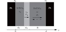
The structure of FTJ with an interface between the ferroelectric BaTiO3 slab and the nonpolar dielectric SrTiO3 slab is shown in Fig. 1. It is assumed that the polarizations of the interface and ferroelectric barrier are perpendicular to the electrode, which can be realized by designing the misfit compression stress from the substrate. According to previous results of first-principles calculation, the thickness of the interface may only be 1– 2 atomic layers.[11] Here, the thickness of interface din is selected as one unit cell (din = 4 Å ), and we do not consider inhomogeneous polarizations throughout BaTiO3 for simplicity. The dipole within the interface is assumed to be pinned, and its direction can be chosen as pointing to the left or right. Once chosen, the direction of the interface dipole will not be switched under an external electric field.
 | Fig. 1. Illustration of the FTJ with a pinned interfacial dipole between dielectric slab SrTiO3 and ferroelectric slab BaTiO3. σ s and σ ′ s stand for screening charge densities of the left and right electrodes, respectively. |
According to the Thomas– Fermi model, [12] the screening potential within the left and right electrodes are

where λ L (λ R) is the screening length of the left (right) electrode and ε L (ε R) is the dielectric constant of the left (right) electrode. σ s stands for the screening charge per unit area of electrode, which is the same in magnitude for the left and right electrodes due to charge conservation. The continuity conditions of electric displacement and electric potential at the boundaries are

where 


and

The overall potential profile U(x) seen by transport electrons across the junction is the superposition of the electrostatic potential − eφ (x), the electronic potential in the electrodes, the rectangular potential Uin in the interface, and the rectangular potential Ud and Uf in dielectric slab and FE slab. The conductance per unit area can be calculated by use of the Landauer formula, [13]

where T(EF, k||) is the transmission coefficient at Fermi energy for a given transverse wave vector, and it can be obtained by solving the Schrö dinger equation for an electron moving in potential U(x) within the formalism of the transfer matrix.[14, 15] In this paper, the right polarization direction is chosen as the positive direction, and the TER ratio is defined as TER = (GL − GR)/GR, where GL and GR are conductances of FTJ for polarization of the FE slab pointing to the left and right, respectively.
To investigate the TER effect of FTJs with a pinned dipole within the composite barrier, we choose symmetric nonmagnetic metal Pt electrodes. Unless otherwise specified, parameters used in this paper are selected as follows. Screening lengths of electrodes are selected as λ L = λ R = 0.45 Å , and dielectric constants ε L = ε R = 2ε 0. The above parameters are typical values for a Pt electrode.[16] It is also assumed that the electron has a free electron mass, the Fermi energy is chosen as EF = 3.0 eV, and the barrier heights are taken as Uin = Ud = Uf = 0.6 eV for the interface, dielectric slab, and FE slab, respectively. FE polarization takes the value 0.26 C/m2, which is the polarization of bulk BaTiO3. The dielectric constant and the thickness of the ferroelectric slab are chosen as ε f = 90 ε 0 and df = 2.4 nm. At the same time, the dielectric constant and thickness of the SrTiO3 slab are chosen as ε d = 300ε 0 and dd = 0.8 nm. The polarization and dielectric constant of the interface take the average value of FE slab and dielectric slab, i.e., |Pin| = |Pf|/2 = 0.13 C/m2, ε in = (ε d + ε f)/2 = 195ε 0.
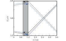
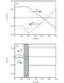
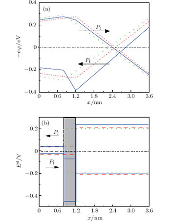
The overall potential energy profile U(x) for different directions of interfacial dipole can be calculated from Eq. (5), and are plotted in Fig. 2. One can see that, in SrTiO3, the potential energy for Pin pointing to BaTiO3 is always higher than the one when Pin directs to SrTiO3, and the potential in BaTiO3 shows the opposite behavior with consideration of the direction of Pin. The crossover of potential occurs within the interface, where the mediation of interfacial dipole on the potential can be explained by the opposite sign of the depolarization field within the interface as the reverse of Pin, which will be discussed later.
 | Fig. 2. Profiles of overall potential energy U(x) for different directions of interface dipole. Solid lines stand for negative Pf, and dashed lines denote positive Pf. Arrows represent the direction of interface dipole. The shadow region represents the interface. |
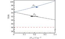
The TER ratio as a function of the magnitude of Pin is shown in Fig. 3, and the dielectric constant ε in is fixed as 195ε 0. It is found that the TER ratio will increase with the increase of interfacial polarization when Pin directs to BaTiO3. For the case of Pin pointing to SrTiO3, the TER ratio decreases with the increase of the magnitude of Pin. The horizontal dashed line and dotted line are plotted for comparison, they correspond to cases without an interface. Specifically, the dashed line denotes the structure where the interface layer is replaced by a dielectric SrTiO3 monolayer, and the dotted line stands for the structure where the interface layer is replaced by a ferroelectric BaTiO3 monolayer. From Fig. 3, we can also find that the existence of an interface between the SrTiO3 slab and the BaTiO3 slab favors the increase of TER, hence, it enhances the performance of the FTJ with symmetric electrodes. Unlike the interface sited between the barrier and the electrode in previous studies, [8] where the TER ratio increases only under some severe conditions.
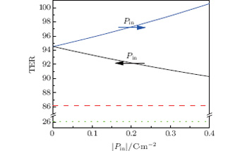 | Fig. 3. TER ratio as a function of the magnitude of Pin. Arrows represent the direction of pinned interface dipole which is assumed to be preassigned. The horizontal dashed line stands for the case that the interface is replaced by an SrTiO3 monolayer, and the horizontal dotted line represents the case that the interface is replaced by a BaTiO3 monolayer. |
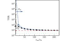
In Fig. 4, the TER ratio is shown as a function of the interfacial dielectric constant (solid lines), where the magnitude of Pin is fixed as 0.13 C/m2. As the decrease of ε in, the TER ratio increases dramatically within the low range of ε in. The influence of ε in on TER is more remarkable than the influence of the magnitude Pin on TER. Furthermore, positive Pin is more in favor of the enhancement of the TER effect. The dashed line and the dotted line, as described in Fig. 3, correspond to the same heterostructures without consideration of an interface.
 | Fig. 4. TER ratio as a function of interfacial dielectric constant ε in (solid lines). Arrows represent the preassigned direction of the pinned interface dipole. The dashed line and the dotted line represent the same situations as described in the caption of Fig. 3. |
 | Fig. 5. (a) Potential energy profile − eφ (eV) and (b) depolarization field within the barrier. Arrows represent the direction of ferroelectric polarization. Solid lines correspond to the case that the interface is considered, dashed lines and dotted lines stand for the situation where the interface is replaced by an SrTiO3 monolayer and a BaTiO3 monolayer, respectively. Shadow region represents the interface. |
To gain a deep insight into the origin of the increase of the TER ratio, the potential distribution − eϕ (x) and the depolarization field Ed(x) within the FTJ are calculated and shown in Fig. 5, where the interface polarization Pin is selected as 0.13 C/m2 (pointing to BaTiO3) and the interface dielectric constant takes the value 50ε 0. Solid lines in Fig. 5 denote the case that the interface is involved. Without consideration of the interface and with reference to zero potential energy, the potentials − eϕ (x) and the depolarization fields are symmetric but opposite in sign with the reverse of Pf (see dashed lines and dotted lines in Fig. 5). The asymmetric potential energy − eϕ (x) and asymmetric depolarization field take place with the occurrence of an interface, the reason is that the depolarization field within the interface is always negative due to the preassigned positive direction of Pin. Let us analyze the potential profile from another point view, when an electron tunnels across the FTJ, it will meet a different potential barrier with the reverse of ferroelectric polarization Pf. Comparing the solid lines with the dashed lines and dotted lines in Fig. 5(a), one can see that the difference between potentials seen by a moving electron for different directions of Pf becomes more significant as the occurrence of an interface, which results in the large TER ratios in Fig. 3 and Fig. 4.
 | Fig. 6. TER ratio as functions of (a) the thickness of BaTiO3 and (b) the thickness of SrTiO3. The dashed line denotes that the polarization of the interfacial dipole is fixed and points to the right, and the solid line stands for the left direction of Pin. Here, the interfacial dielectric constant is chosen as 50ε 0. |
TER ratio dependence on the thickness of SrTiO3 slab and BaTiO3 slab for different directions of interface dipole are illustrated in Fig. 6, where the parameters of the interface are chosen as | Pin| = 0.13 C/m2, ε in = 50ε 0, and din = 0.4 nm. The TER ratio increases with the increase of the thickness of SrTiO3 and BaTiO3. It is well known that the thicker the barrier is, the smaller the tunneling current. Although the TER ratio becomes large as the increase of barrier thickness, the tunneling current becomes too small to be detected for a thick barrier. The optimal selection of barriers’ thickness in the FTJ with a composite barrier is also very important.[17]
In summary, the interface between the dielectric SrTiO3 slab and the ferroelectric BaTiO3 slab in the FTJ with symmetric electrodes is investigated, and TER ratio dependence on the polarization and dielectric constant of an interface with a pinned dipole are calculated and discussed. It is found that the above interface favors the increase of the TER ratio. A significant TER effect can be achieved when the interface possesses large polarization pointing to BaTiO3 and a low dielectric constant. We hope our studies might supply an avenue to engineer the interface artificially in nanoscale and enhance the functionalities of nanodevices.
| 1 |
|
| 2 |
|
| 3 |
|
| 4 |
|
| 5 |
|
| 6 |
|
| 7 |
|
| 8 |
|
| 9 |
|
| 10 |
|
| 11 |
|
| 12 |
|
| 13 |
|
| 14 |
|
| 15 |
|
| 16 |
|
| 17 |
|