


Fiber laser pumped burst-mode operated picosecond mid-infrared laser*
[Wei Kai-Huaa), c) , Jiang Pei-Peia) , Wu Boa) , Chen Taoa), b) , Shen Yong-Hanga)†  ]
]
]
|
|


Corresponding author. E-mail: physyh@zju.edu.cn
Project supported by the National Natural Science Foundation of China (Grant No. 61078015) and the National Basic Research Program of China (Grant No. 2011CB311803).
We demonstrate a compact periodically poled MgO-doped lithium niobate (MgO:PPLN)-based optical parametric oscillator (OPO) quasi-synchronously pumped by a fiber laser system with burst-mode operation. The pump source is a peak-power-selectable pulse-multiplied picosecond Yb fiber laser. The chirped pulses from a figure of eight-cavity mode-locked fiber laser seed are narrowed to a duration of less than 50 ps using an FBG reflector and a circulator. The narrowed pulses are directed to pass through a pulse multiplier and to form pulse bunches, each of which is composed of 13 sub-pulses. The obtained pulse bunches are amplified by two-stage fiber pre-amplifiers: one-stage is core-pumped and the other is cladding-pumped. A fiberized acousto–optic modulator is inserted to control the pulse repetition rate (PRR) of the pulse bunches before they are power-amplified in the final amplifier stage with a large mode area (LMA) PM Yb-doped fiber. The maximum average powers from the final amplifier are 85 W, 60 W, and 45 W, respectively, corresponding to the PRR of 2.72 MHz, 1.36 MHz, and 0.68 MHz. The amplified pulses are directed to pump an MgO:PPLN-based optical parametric oscillator (OPO). A maximum peak power at 3.45 μm is obtained approximately to be 8.4 kW. Detailed performance characteristics are presented.
Mid-infrared (MIR) laser sources in a range of 3 μ m– 5 μ m are important components in environmental monitoring, missile countermeasures, and medical diagnostics.[1– 3] Picosecond or femtosecond pulsed fiber laser-pumped optical parametric oscillator (OPO) represents one kind of important approach to realize ultra-short MIR laser output. Because the output properties of the OPO are dominated mainly by the pump source and the nonlinear crystal, such a fiber laser-pumped scheme can offer compactness, good beam quality, high peak and average power, and simple thermal management.[4– 9] Owing to the short pulse duration of the pump, however, the synchronous pumping scheme must be adopted. Normally there is a trade-off between the cavity size of the OPO and the peak power obtainable.
To shorten the OPO cavity length, the fiber laser should operate at a high repetition rate up to several hundreds of MHz or even GHz. In this aspect, many studies have been carried out. The harmonic mode-locking technology is a popular means to obtain high repetition rate pulses in fiber lasers, [10– 12] although the stabilities of these lasers cannot be fully guaranteed under a high repetition rate operation over GHz. In addition to these, some novel methods were developed to increase the repetition rate of fiber lasers. In 2005, Ilday et al. reported a passively mode-locked Yb-doped fiber laser with a repetition rate of 200 MHz by using nonlinear polarization rotation (NPR) technique.[13] In 2009, Zhao et al.demonstrated an NPR-based Er-doped fiber laser with a high fundamental repetition rate of 234 MHz, operated in strong normal dispersion regime.[14] In 2012, Yang et al. achieved an Yb-doped ring laser with a repetition rate of 605 MHz and a pulse duration of 502 fs, operated at a wavelength of 1030 nm.[15] In the above-mentioned work, hundreds of MHz rate operations were achieved using the NPR technique. However, the purpose for higher repetition rate was impeded by the difficulty in obtaining the shorter cavity length due to the size limitation to the fiber-coupled components. We note that early in 2006 there was a report on a novel pulse multiplier by using two cascaded loop-structured fiber couplers to multiply the repetition rate from 5.68 MHz to 22.8 MHz.[16] To compensate for the problem of comparatively low peak power under higher pulse repetition rate, the burst-mode operation would be a feasible way to maintain the high peak power of the laser. In 2012, Kalaycioğ lu et al. developed a burst-mode operated Yb-doped fiber amplifier to achieve a high peak power output at a high repetition rate.[17]
On the other hand, the peak power of the pump laser, as well as the MIR output, would be greatly dependent on its pulse repetition rate, which is also a key issue in many applications. In terms of industrial processes, MIR lasers with a relatively low peak power are beneficial to the realization of non-intrusive detection. In contrast, in terms of missile countermeasures, MIR lasers with the high peak power are favorable to the saturature of an IR detector with little atmospheric absorption.[18, 19] Of course, nonlinear crystals also play an important role in obtaining an efficient high power MIR laser. Among those OPO crystals, MgO:PPLN crystal is extensively applied because of its characteristics of high effective nonlinear coefficient, long interacting length, good laser power sustainability, and wide spectral transmissive range.[20, 21]
In the present work, we experimentally demonstrate a peak-power-selectable MgO:PPLN-based MIR laser with a burst-mode high repetition rate output. On the basis of the preliminary work that was reported earlier, [4] the pump source is a peak-power-selectable pulse-multiplied picosecond Yb fiber laser. The chirped pulses from a figure of eight-cavity mode-locked fiber laser seed are narrowed to a duration of less than 50 ps using an FBG reflector and a circulator. The narrowed pulses are directed to pass through a pulse multiplier and to form pulse bunches, each of which is composed of 13 sub-pulses. The obtained pulse bunches are amplified by two-stage fiber pre-amplifiers: one-stage is core-pumped and the other is cladding-pumped. A fiberized acousto– optic modulator is inserted to control the pulse repetition rate (PRR) of the pulse bunches before they were power-amplified in the final amplifier stage with a large mode area (LMA) PM Yb-doped fiber. The maximum average powers from the final amplifier are 85 W, 60 W, and 45 W, respectively, corresponding to the PRR of 2.72 MHz, 1.36 MHz, and 0.68 MHz. The amplified pulses were directed to pump an MgO:PPLN-based optical parametric oscillator (OPO). Detailed performance characteristics are investigated. The OPO pump threshold is measured to decrease from 17.3 W to 9.3 W with PRR decreasing from 2.72 MHz to 0.68 MHz and the faster rising edge is observed with the lower PRR from signal pulse envelope, owing to the higher peak power from the pump.
A peak-power-selectable linearly polarized Yb fiber laser with burst-mode operation is constructed as the pump source. The configuration of the whole fiber laser system is illustrated in Fig. 1. The MOPA structured fiber laser consists of a mode locked seed fiber laser, a spectrum purifier, a pulse multiplier, one-stage core-pumped pre-amplifier, an acousto– optic modulator-based pulse picker, and a two-stage clad-pumped fiber amplifiers.
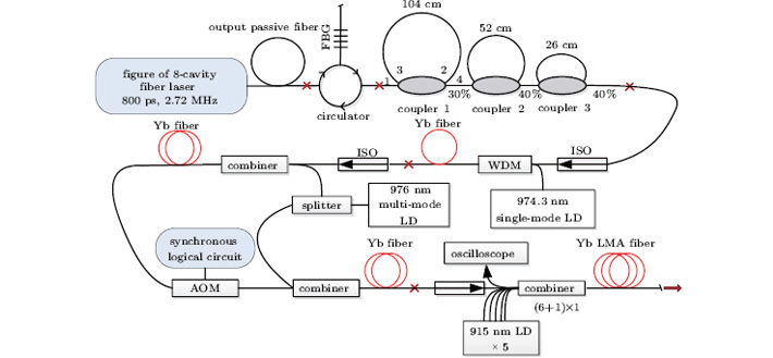 | Fig. 1. Experimental setup of the peak-power-selectable fiber laser system with pulse bunch output. |
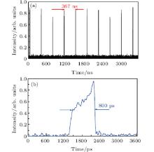
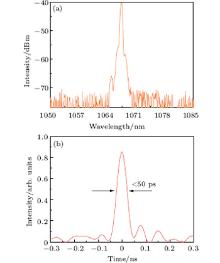
The seed source of the master-oscillator-power-amplifier (MOPA) is a figure-of-eight-cavity structured mode-locked fiber laser. A detailed introduction to this mode-locked seed can be found in Ref. [4]. The pulse trains are measured by using an InGaAs detector with a bandwidth of 20 GHz and a broadband oscilloscope while the spectra are measured via a spectrum analyzer with a resolution of 0.02 nm (ANDO, AQ6317C). Under a pump power of 780 mW, a seed-laser-emitted stable pulse train has an average power of 45 mW and a pulse duration of 800 ps at a pulse repetition rate of 2.72 MHz corresponding to the total cavity length of 75 m. Under this pump condition, a pulse-stable mode-locking operation is observed as shown in Fig. 2. The output 3-dB bandwidth from the seed laser is 10 nm, which is too large a spectral width to pump an MgO:PPLN-based OPO.[22] To purify the spectrum, the output fiber of the seed laser is spliced to a fiber Bragg grating (FBG) reflector via a three-port circulator, through which the spectrum and the chirped pulse are narrowed, as shown in Fig. 3. The bandwidth and pulse duration after spectrum purification are 0.15 nm and less than 50 ps, respectively.
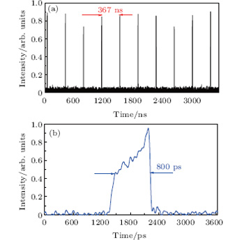 | Fig. 2. Pulse train (a) and the individual pulse (b) from the seed. |
 | Fig. 3. Spectrum (a) and the individual pulse (b) after spectrum purification. |
A high power picosecond fiber laser, such as a harmonic mode-locked fiber laser, with a high repetition rate up to GHz could be used to lessen the OPO cavity length. However, as a compromise, the pulse energy and the peak power are both relatively low. Also, the harmonic mode-locked fiber lasers have the disadvantages of unstable peak power and inaccurate repetition rate. Under this circumstance, a novel all-optic pulse multiplier consisting of three cascaded 2× 2 fiber couplers was investigated in our previous work.[4] Each fiber coupler is loop-configured by splicing two ports together (port 2 and port 3), as shown in Fig. 1. Port 1 is the input port, through which the individual pulse is divided into two sub-pulses output from port 2 and port 4. The sub-pulse output from port 4 acts as the first pulse for a single multiplier, while the sub-pulse from port 2 is transmitted back to port 3 to obtain the second sub-pulse. The lengths of the three loops are set to be 104 cm, 52 cm, and 26 cm, respectively. The coupling ratio of the fiber couplers is optimized to make the intensity of the sub-pulses more even and then the OPO conversion efficiencyincreases. For example, using coupler with a coupling ratio of 30/70, the amplitude ratios of the first four sub-pulses are 30%, 49%, 14.7%, and 4.4%, respectively. It is obvious that the sub-pulse amplitude is almost negligible after the first four circulations because it is less than 1.32% of the initial intensity. For the coupler with a coupling ratio of 40/60, the amplitude ratios of the first four sub-pulses are 40%, 36%, 14.4%, and 5.8%. The output pulse envelope from this pulse multiplier is illustrated in Fig. 4. Each individual pulse is enabled to become a pulse bunch composed of about 13 sub-pulses with similar pulse shapes. The time-interval between each sub-pulse is 1.26 ns, corresponding to a loop length of 26 cm. This means that a high pulse repetition rate is obtained up to 793 MHz within each pulse bunch. Such a pulse multiplied laser is able to be amplified further in a fiber amplifier to simultaneously realize a high peak power and high average power.
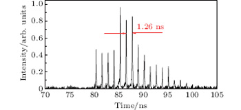 | Fig. 4. Sub-pulse structures of a typical pulse bunch output from the pulse multiplier. |
Owing to the insertion loss of the spectrum purifier, the seed power decreases down to 800 μ W, which is not enough to be directly amplified up to nearly 100 W. The narrowed and multiplied pulses are directed to pass a core-pumped Yb fiber pre-amplifier at first, as illustrated in Fig. 1. The output fiber from the pulse multiplier is spliced to a polarization-independent isolator (ISO), followed by a 980-nm/1064-nm wavelength division multiplexing (WDM) coupler. A piece of home-made Yb-doped fiber with a length of 0.5 m is pumped by a single-mode fiber-pigtailed diode laser with a center wavelength of 974.36 nm and a spectral full width at half maximum (FWHM) of 0.2 nm (Oclaro, LC95A76ULR-20R), which is driven by an LD/TEC driver. The output laser power and spectral FWHM after this stage are 6 mW and 0.16 nm, respectively.
To obtain both the high average power and the peak power, the laser pulses are arranged to further pass through a clad-pumped Yb fiber pre-amplifier, in which a fiber-pigtailed acousto– optic modulator (AOM) is inserted as the pulse picking device. As illustrated in Fig. 1, this pre-amplifier is actually composed of three sections, i.e., the AOM-based pulse-picker and two Yb fiber amplifiers. The output from a fiber-pigtailed multimode LD pump laser working at 976 nm is divided into two parts by a multi-mode fiber splitter to pump two sub-amplifiers simultaneously. These two sub-amplifiers are all simply configured by a (1 + 1) × 1 multi-mode fiber coupler followed by a piece of home-made Yb-doped fiber, which is 5 m in length with a core and clad diameter of 6 μ m and 128 μ m, respectively. The fiber pigtailed AOM is configured to pass only the first-order diffraction signal to avoid any unexpected pulse. Figure 5 presents the principle configuration of the first-order diffraction transmission AOM. Its on/off state is controlled by a signal output from a mono-chip processor, which is superposed to the 100-MHz radio-frequency (RF) driving signal of the AOM. Such a configuration is superior to the ordinary configured AOM, which passes the signal under no diffraction. In those ordinary AOMs, some unexpected pulses would not be totally blocked because the diffraction efficiency was only 80%, which might result in unexpected pulse amplification. In the experiment, the pulse repetition rate is reduced from 2.72 MHz to 1.36 MHz, 0.68 MHz, and 0.34 MHz (that is, 2.72/2 MHz, 2.72/4 MHz, 2.72/8 MHz, respectively), etc. Under a pump power of 8 W, the average power of approximately 2 W could be obtained after this pre-amplifier stage.
 | Fig. 5. Structure of the AOM configured in the first-order diffraction transmission. C1: input collimator; C2: output collimator. |
The output fiber from the above amplifier is spliced to a fiber pigtailed polarization-maintaining (PM) isolator, resulting in a power reduction down to 0.8 W. This power is still sufficient to be amplified to nearly 100 W in the final linearly polarized power amplifier, in which its configuration is also illustrated in Fig. 1. Figure 6 shows the output power dependence on the pump power from the final fiber-amplifier with an inlet showing the spectra with the same output (30 W) at 2.72 MHz, 1.36 MHz, and 0.68 MHz. Stronger stimulated Raman scattering (SRS) and the self-phase modulation (SPM) phenomena, which can be seen from the broadened spectra, are observed with the decrease of the PRR, owing to the increase of the peak power. The PRR lower than 0.68 MHz is considered to be unsuitable to obtain a high power output nor to pump the OPO, owing to SRS-induced energy shift. Under an acceptable level of SRS, the maximum powers of amplifier output at 2.72 MHz, 1.36 MHz, and 0.68 MHz are 85 W, 60 W, and 45 W, respectively, with almost the same slope-efficiency of about 65%. The polarization extinction ratio of the linearly polarized fiber laser output is measured to be better than 14 dB.
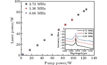 | Fig. 6. Output power from the main amplifier versus pump power. The inset shows the spectra operated at 2.72 MHz, 1.36 MHz, and 0.68 MHz under the same pump power, respectively. |
A schematic diagram of the fiber laser-pumped OPO is illustrated in Fig. 7. The OPO resonator is configured in a single passing singly resonant (SPSR) linear cavity structure. The fiber laser output is collimated using a lens with a focal length of 15 mm, followed by a free-space PM-ISO with an insertion loss of 1.1 dB. The linearly polarized laser is further focused onto a MgO:PPLN crystal with a beam waist of 250 mm while its polarization direction is aligned in the Z axis of the MgO:PPLN using a half wave plate (not shown in Fig. 7). Considering the thermal lens effect at the output surface of the main fiber amplifier, the pump laser is initially adjusted to focus onto the output end of the MgO:PPLN crystal at a low power level. The plane input mirror (M1) is coated with a high-reflection (HR) film for signal (R > 99.7% over 1.4 μ m– 1.7 μ m) and idler band (3 μ m– 4 μ m), and high transmission coated for pump (T > 98%). The output coupler (M2) is a concave mirror with a curvature radius of 200 mm and coated with HR for signal (R > 99.7% over 1.4 μ m– 1.7 μ m), and high transmission for the pump and the idler (3 μ m– 4 μ m) (T > 98%). The undepleted pump and the OPO signal are highly reflected by M3 (R > 99.8%). The signal and the idler output are extracted through M2, while the idler power is measured after M3.
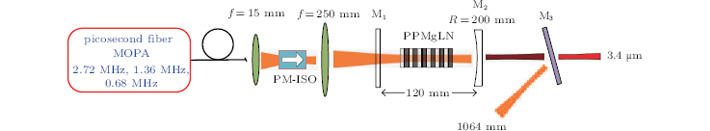 | Fig. 7. Experimental setup of the compact OPO quasi-synchronously pumped by a peak-power-selectable fiber laser. |
The cavity length is adjusted to about 12 cm to meet the condition of quasi-synchronously pumping. Figure 8 shows the output spectrum of the OPO containing the pump and the signal light. The signal wavelength is measured to be 1548 nm, corresponding to an idler wavelength of 3.45 μ m. The inversion period of the MgO:PPLN is correspondingly 30.5 μ m. When the pump power is beyond 10 W at 0.68 MHz, a stable signal pulse train can be obtained (as illustrated in Fig. 9).
 | Fig. 8. Spectrum of the OPO output. |
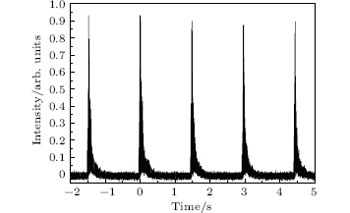 | Fig. 9. Signal pulse train at 0.68 MHz. |
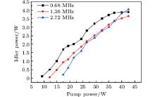
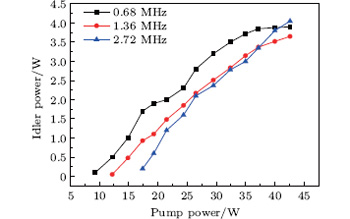
The idler output power dependence on pump power is illustrated in Fig. 10 at 2.72 MHz, 1.36 MHz, and 0.68 MHz. The oscillation thresholds of the OPO are 17.3 W, 12.1 W, and 9.3 W, respectively, at 2.72 MHz, 1.36 MHz, and 0.68 MHz, while the maximum idler output powers are 4.1 W, 3.7 W, and 3.9 W, corresponding to conversion efficiencies of 9.5%, 8.7%, and 9.2%, respectively. Clearly, the lower PRR favors the higher idler power output at a lower pump power level but is easily saturated at a high pump level. This is mainly due to the different peak power in the OPO. For instance, at the same MIR average power of 3.8 W, the idler peak power is calculated to be 8.4 kW at 0.68 MHz, while it is only 2.1 kW at 2.72 MHz. The high peak powers of the signal and the idler in the cavity would be likely to result in more back-conversions, considering the high reflectivity of the output coupler M2 in the signal band.
 | Fig. 10. Idler output power dependence on pump power at 2.72 MHz, 1.36 MHz, and 0.68 MHz. |
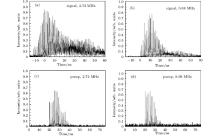
Measured at an idler power of 2 W, the pulse details of signal pulse bunch were recorded at 2.72 MHz and 0.68 MHz, as shown in Figs. 11(a) and 11(b), respectively. It is obvious that the pulse envelope at 0.68 MHz has a faster rising edge (8 ns) than at 2.72 MHz (11 ns), owing to the higher pump peak power at 0.68 MHz. From Figs. 11(a) and 11(b), a long pulse trail is observed, which is ascribed to the high signal reflectivity in the OPO cavity. The gray and black parts in the figure represent the actual pulse densities, the black part represents dense pulse, which is a result of the inexact synchronization induced by the inaccurate sub-pulse time-interval emitted from the pump source.
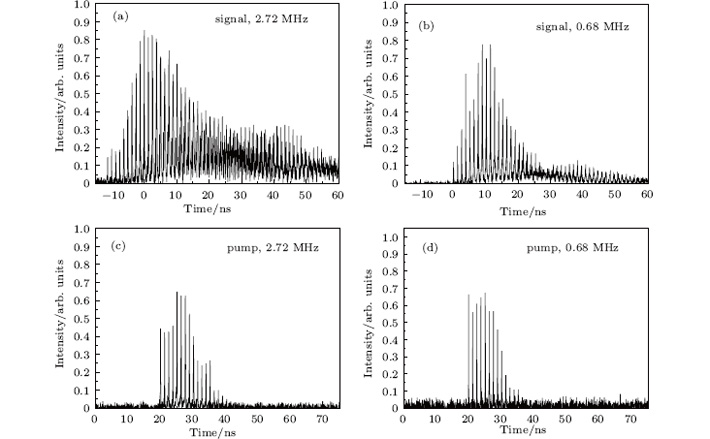 | Fig. 11. Comparison of the OPO signal pulse envelope between at 2.72 MHz (a) and at 0.68 MHz (b), and comparison of pump pulse envelope between at 2.72 MHz (c) and at 0.68 MHz (d). |
To explain the difference in OPO signal envelope shape between 0.68 MHz and 2.72 MHz, the pump pulse envelopes output from the final fiber amplifier are also measured at the same average power. As shown in Figs. 11(c) and 11(d), the number of the sub-pulses is less at 0.68 MHz than at 2.72 MHz while its intensity reaches the maximum more quickly. The black parts in Figs. 11(c) and 11(d) are actually the overlapped pulses, which look broader than single sub-pulse as shown in Fig. 4. Obviously, such a phenomenon is due to the inaccurate lengths of three looped couplers, which are not strictly in multiple. This might be improved by monitoring the broadband oscilloscope in future work.
In this paper, we experimentally demonstrate a picosecond MIR laser source operating in a burst-mode. A peak power selectable picosecond fiber laser system with burst-mode operation is developed to pump a MgO:PPLN-based optical parametric oscillator. The optical parametric oscillator is designed to be quasi-synchronously pumped by the fiber laser and is thus compact in size because the sub-pulse repetition rate of the fiber laser is as high as 793 MHz. Although the fiber laser can be amplified to output a linearly polarized average power of about 100 W, the optical parametric oscillator is found to be saturated under a pump power of about 40 W. A maximum average power of 4.1 W at 3.45 μ m is obtained with a pump-to-idler conversion efficiency of about 10%. The maximum peak power at 3.45 μ m is estimated to be about 8.4 kW.
To improve the performance of the MIR laser system, several points need to be optimized. First, the loop lengths need to be more finely controlled. If this is done, then the quasi-synchronous scheme will be more efficient. Second, the optical parametric oscillator cavity mirrors need to be optimized, especially for the signal reflectivity of the output coupler. Thus the problem of signal saturation can be lessened to some extent. As a result, higher picosecond pulse burst output in the MIR can be expected in our future work.
| 1 |
|
| 2 |
|
| 3 |
|
| 4 |
|
| 5 |
|
| 6 |
|
| 7 |
|
| 8 |
|
| 9 |
|
| 10 |
|
| 11 |
|
| 12 |
|
| 13 |
|
| 14 |
|
| 15 |
|
| 16 |
|
| 17 |
|
| 18 |
|
| 19 |
|
| 20 |
|
| 21 |
|
| 22 |
|