Corresponding author. E-mail: wanguiuc@mail.xjtu.edu.cn
Project supported by the National Natural Science Foundation of China (Grant No. 61231003).
Based on conformal construction of physical model in a three-dimensional Cartesian grid, an integral-based conformal convolutional perfectly matched layer (CPML) is given for solving the truncation problem of the open port when the enlarged cell technique conformal finite-difference time-domain (ECT-CFDTD) method is used to simulate the wave propagation inside a perfect electric conductor (PEC) waveguide. The algorithm has the same numerical stability as the ECT-CFDTD method. For the long-time propagation problems of an evanescent wave in a waveguide, several numerical simulations are performed to analyze the reflection error by sweeping the constitutive parameters of the integral-based conformal CPML. Our numerical results show that the integral-based conformal CPML can be used to efficiently truncate the open port of the waveguide.
The finite-difference time-domain (FDTD) method has been proven to be an effective algorithm that provides accurate predictions of field behaviors for various electromagnetic interaction problems.[1] Unfortunately, in its original formulation with orthogonal meshes, the method does not provide a good accuracy when curved surfaces are present. The earliest way of addressing the problem of curved surfaces was to use staircase approximations. Although trivially simple, this method is known to introduce errors, which remain there even when the mesh size is very small.[2] An alternative approach to the problem is to use locally distorted meshes where the basic Cartesian grids are modified only in the vicinity of the metal boundaries. One such a scheme, i.e., the contour path FDTD (CP-FDTD) scheme, [3– 6] is formulated in terms of the integral form of Maxwell’ s equations instead of the usual differential form. A major advantage of this approach, when compared with other conformal techniques, is that the simplicity and efficiency of the Cartesian mesh are retained throughout the majority of the problem space and only those nodes adjacent to the curved surface need to be specially investigated. However, the time step size of CP-FDTD scheme must be reduced to ensure stability, owing to the presence of small irregular cells near the boundary. To solve the time step reduction problem, an enlarged cell technique conformal FDTD (ECT-CFDTD) method is introduced.[7, 8] In the ECT-CFDTD method, the small irregular cells near the material interface are enlarged into their adjacent cells to ensure stability, even at the maximum time step of the CFL condition for the conventional FDTD method.
When the ECT-CFDTD method is used to simulate the wave propagation in a passive waveguide device, the conformal truncation of the open boundary of the waveguide cannot be avoided. In this paper, we discuss the truncation technique that is used in the ECT-CFDTD method.
In 1994, Berenger proposed the split-field perfectly matched layer absorbing media, [9] which introduced an artificial lossy tensor with both electric and magnetic conductivities for decaying the electromagnetic waves. This method was proven to be the most efficient technique for the truncation of FDTD lattices at that time, [9– 14] and it has been widely used since then. Nevertheless, a limitation of the PML formulations that are commonly used is that they are ineffective for absorbing evanescent waves. As a result, the simulation region must be set to be large enough so that the evanescent waves are sufficiently decayed, which widely reduces the capability of the numerical simulation. In 1996, Kuzuolog and Mittra introduced a strictly causal form of the PML by simply shifting the frequency-dependent pole off the real axis and into the negative-imaginary half of complex plane.[15] This is named the complex frequency shifted PML (CFS-PML). It has been shown that the CFS-PML is highly efficient for absorbing the evanescent waves with a long time history. Unfortunately, this method is very complicated to implement in three-dimensional (3D) problems. Based on the CFS-PML, Roden and Gedney proposed the convolutional PML (CPML) by using the recursive algorithm for absorbing the evanescent waves.[16] It has been shown that this can be applied to the inhomogeneous, lossy anisotropic, and dispersive or nonlinear media. CPML has already been used to truncate the open boundaries in 2.5-dimensional and 3D electromagnetic PIC (particle in cell) simulations, [17– 21] and it has also been used to truncate the open boundaries of waveguides in 3D coordinates with staircasing boundaries.[22]
Unlike the staircasing FDTD method, in the ECT-CFDTD method the electromotive force along the boundary of the small area face is enlarged by the electromotive forces of adjacent faces using linear interpolation with pre-calculated weighting parameters, so the CPML method cannot be directly used in the ECT-CFDTD method to solve the wave propagation problems in waveguides. Here, we present the conformal CPML technique for the ECT-CFDTD method to truncate the open boundaries in waveguides.
Before giving the formulas of conformal CPML, the definition of the conformal grid system that is used in this paper must be given.
To give a boundary representation (B-rep) of a shape, [23] we give the method of reconstructing a model in a discrete grid.[24] In order to describe the topology of discrete boundaries in a discrete grid system, the relative orientation relationship between line and face on one partially filled cell (PFC) for a PEC geometry should be defined.
Suppose that the direction of a grid line is along one coordinate axis, u0, u1, and u2 are used to define the direction of the grid lines, (u0, u1, u2) may be (x, y, z), (y, z, x) or (z, x, y). For convenience, we correspondingly map x, y, and z to 0, 1, and 2. If the value of u0 is set to be either 0, 1 or 2, then the values of u1 and u2 can be given as

where “ mod” is the modulus operator.
Lq is used to represent a cell line with index q and it has a natural orientation which is denoted as uq, 0. In the same way, the cell face with index p is denoted as Sp. The natural orientation of Sp is defined as ũ p, 0. As in Eq. (1), we give the induced orientations by uq, 0 and ũ p, 0 as follows:


Based on the definition of the natural orientation of grid elements, the relative orientation between line and face on one PFC can be determined. Suppose that the line Lq is one boundary edge of the face Sp, if the natural orientation of Lq is reverse to the direction of the closed boundary orientation induced by natural orientation of Sp, we say that the orientation of Lq is relatively reverse to the orientation of Sp. On the contrary, we say that the orientation of Lq is relatively consistent with the orientation of Sp. The relative orientation relationship between Lq and Sp is noted as 


Based on the definition of Eq. (1), the PML formulation is proposed in the stretched coordinate space in Ref. [16], and the corresponding equations in frequency domain are


where sum is the CFS PML factor, [15]κ um is the stretch factor, and α um is homogeneous to a conductivity.
Performing the Fourier transform on Eqs. (4) and (5), the convolutional formulas in the time domain can be obtained as


where 

In a discrete grid system, σ , κ , and α are defined on discrete grid elements, all of them are three-dimensional (3D) vectors. For example, on an edge element, σ is defined as (σ u0ijk, 0, σ u0ijk, 1, σ u0ijk, 2), where u0 is the direction of the edge element and (i, j, k) is its vector index.[16]
According to the discrete definition of PML factors, based on Eqs. (7) and (8), the CPML expressions can be given as follows by using the recursive convolution method:[16]
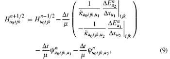


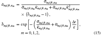
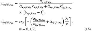
where σ u0ijk, um corresponds to the partial differential along direction um. In the same way, α u0ijk, um, κ u0ijk, um, σ ̃ u0ijk, um, α ̃ u0ijk, um, and κ ̃ u0ijk, um are defined. It is worth pointing out that σ u0ijk, um, α u0ijk, um, and κ u0ijk, um are defined at the midpoint of mesh line Luijk, σ ̃ u0ijk, um, α ̃ u0ijk, um, and κ ̃ u0ijk, um are defined in the barycenter of the mesh face Suijk.
To give the conformal CPML formulas, the general formulas of ECT-CFDTD are first given in the oriented conformal grids.
Based on the relative orientation relationships between the edges and faces in a discrete grid, the electromotive force along the oriented boundary of an arbitrary face Sp can be given as

where ∂ Sp is the boundary of Sp, and 
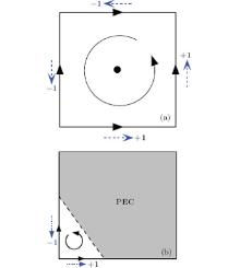
As shown in Fig. 2, for the ECT-CFDTD method, after calculating all electromotive forces in a regular way, the electromotive forces of adjacent faces are used to enlarge the value around the small face Sp to avoid the reduction of the time step. The enlarged electromotive force and area can be expressed, respectively, as
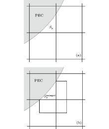 | Fig. 2. Process of cell enlargement in the ECT, showing (a) an irregular cell with small area face Sp and the enlargement of the small area of face Sp to a stable area. |


Moreover, for the intruded face Sq, its corresponding values can be given by the averaging algorithm as


where Rq, p is the interpolation ratio of the electromotive force from face Sp to face Sq, and it is also the averaging ratio of electromotive force from face Sq to face Sp.
The corresponding magnetic fields on a small face and an intruded face can be advanced by the following equations,


and the electric fields can be advanced as


where 


In the following, the conformal CPML formulation will be directly presented for the ECT-CFDTD method. Advancing equations for electric fields remain unchanged as Eqs. (12)– (14). Advancing equations for magnetic fields on small faces and intruded faces can be separately given as

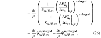


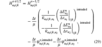


where the space difference operation on a small face is enlarged in the same manner as Eqs. (18) and (19), the corresponding operation on an intruded face is averaged in the same manner as Eqs. (20) and (21).
We reformulate Eqs. (26)– (31) in the concise forms of electromotive and magnetomotive forces. To multiply both sides of Eqs. (9)– (14) with a proper discrete area, and using the following transform, the difference operation in Eqs. (9)– (14) can be transformed into the integral formulation,

with

with

with

and with

By substituting Eqs. (32)– (35) into Eqs. (26)– (31), we obtain the equations of conformal CPML in the integral form as follows:


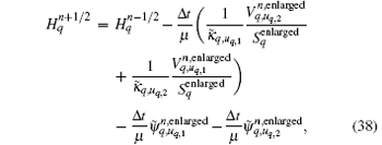


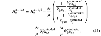


Based on the relative orientation relationship definition, the above conformal CPML formulas can be coherent everywhere and are easily implemented for coding.
In simulation, the constitutive parameters of CPML σ , κ , and α are set in the same manner as that in Ref. [16], and can be obtained as


where the definition of σ max is given by


where R(0) is the reflection at a normal incidence. α is homogeneous to a conductivity, it is assumed to absorb evanescent waves. It is obvious from Eq. (6) that the performance of CPML medium depends on the ratio of the frequency of interest to the frequency[14]

For f ≫ fα , parameter α is negligible in Eq. (6), so that the medium is a regular PML. Conversely, for f ≪ fα , the stretched coordinate is real and the medium no longer absorbs the waves. By conducting a lot of numerical experiments, efficiently absorbing the evanescent waves with a frequency of about f0, α is set as

where α 0 = 2π ε 0f0.
In this section, we first give the verification of the conformal grid system by using the ECT-CFDTD method to simulate a cylindrical cavity. Then, we give some numerical experiments for testing the ability to truncate the conformal CPML.
To validate the conformal grid system, we use the ECT-CFDTD method to simulate a cylindrical cavity.
The cylindrical cavity model is chosen to be the same as that in Ref. [8]: its radius is 5.5 mm, and the height is 9 mm. The origin point of the discrete space domain is set to be in the center of the model. The cylinder is parallel to the z axis. The spatial increment is set to be 1.0 mm in all three directions, and is denoted as Δ x, Δ y, and Δ z. To ensure stability, the time step is set as

where c is the speed of light.
The excitation source is chosen as a dipole in the form of a sine-modulated Gaussian pulse that occupies one grid step length from (− 3Δ x, − 3Δ y, − 3Δ z) along the z axis. The current density along z axis is

where f is the modulation frequency, τ is the pulse duration, and t0 is the peak time of the pulse. In simulation, we choose f = 20.0 GHz, τ = 40/f, and t0 = 50/f.
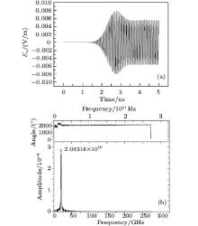
The test value is set to be the value of electric fields along z axis at (3Δ x, 3Δ y, 3Δ z), which is denoted as Ez. The time history of test value and the spectrum are shown in Fig. 3. The theoretical resonant frequency of the TM010 mode is 20.8774 GHz, the numerical result is 20.8316 GHz, and the error is 0.2%. These results validate the correctness of the conformal mesh system.
To validate the effectiveness of the conformal CPML method in truncation of the open boundary, we adopt a two-step procedure to calculate the relative error caused by the CPML. The first step is to place both the right-hand and left-hand sides of conformal CPML media at a place far enough away from the test point at (3Δ x, 3Δ y, 3Δ z), and then calculate the electromagnetic field propagating in the waveguide of radius 5.5 mm before the signal reflected from the CPML arrives at the test points by using the ECT-CFDTD method. Such a calculated electric field is not contaminated by the reflected signal and it can be considered as the reference solution, noted by Xref(t). The second step is to move the conformal CPML media close to the test points. We then calculate the electromagnetic field, which includes the signal reflected from the CPML, and denote the electric field as X(t). The relative error is defined as

where max {| Xref(t)| } denotes the maximum value of reference solution over the full time calculation.
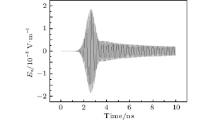
The excitation source is chosen as the source described by Eq. (52). In our simulation, we choose f = 20.0 GHz, τ = 10/f, and t0 = 20/f. The dipole source occupies one grid step length from (− 3Δ x, − 3Δ y, − 3Δ z) along the z axis, and it can only excite the TM mode. The cutoff frequency of TM01 of this model is 20.878 GHz. Based on the frequency spectrum analysis, the excitation source can excite both travelling and evanescent waves. The calculated reference solution is shown in Fig. 4.
In the second step, the length of the waveguide model is set to be 9.0 mm, the two ends of the model are also truncated by the conformal CPML. The length from the test point to the truncated interface is one Δ z. During the simulation, 10 cell-thick CPML layers terminate the grid, R(0) is set to be e− 16, σ ratio is chosen from the interval (3, 11), κ max is chosen from the interval (1, 25). For different values of α max, i.e., 0.0, 0.25, 0.5, 0.75, 1.0, 1.25, and 1.5, the maximum relative errors are given as a function of σ ratio and κ max, as shown in Fig. 5. The results show that when α max is in the interval (0.5, 1.0), CPML can efficiently truncate the wave propagation.
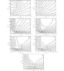 | Fig. 5. Maximum relative errors as a function of σ ratio and κ max with f = 20 GHz at α max = 0.0 (a), 0.25 (b), 0.5 (c), 0.75 (d), 1.0 (e), 1.25 (f), and 1.5 (g). |
The results also show that as the value α max is fixed, if σ ratio < 7.0, then CPML has no long time truncation capability, and the setting of different values of κ max cannot avoid this situation. Conversely, when σ ratio ≥ 7.0, only if κ max > 1 is satisfied can CPML efficiently truncate the evanescent waves, and the truncation error could be as low as − 80 dB. Figures 6 and 7 give the results with α max = 0.75, κ max = 17, and the values of σ ratio being 7.0 and 9.0, respectively.
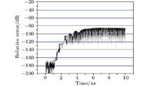 | Fig. 6. Error in the electric field intensity relative to the field’ s maximum amplitude versus time with f = 20 GHz, α max = 0.75, κ max = 17, and σ ratio = 7.0. |
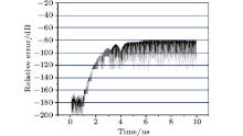 | Fig. 7. Error in the electric field intensity relative to the field maximum amplitude versus time with f = 20 GHz, α max = 0.75, κ max = 17, and σ ratio = 9.0. |
Equation (49) shows that the selection manner of α is related to the frequency of interest, σ and κ are not constrained by the special frequency. To test the relationship of σ , κ , and α with the cutoff frequency, we change the parameters of the model as shown in Table 1. The models with longer length are used to compute the reference values, and those that have shorter lengths are used to compute their values with reflection errors of CPML. The setting manners of other parameters remain unchanged. The last column “ time” in Table 1 refers to the total computational time length.
| Table 1. Different models for testing the relationship of PML parameters with the working frequency. |
For the above different numerical models, σ and κ are not changed, the value of α is chosen according to Eq. (49), and the working intervals of α are given in Table 2 for different cutoff frequencies. As shown in Figs. 8– 10, the values of σ and κ are not constrained by the cutoff frequencies, α is approximately chosen as the mid value of its working interval, the truncation error of CPML could be as low as − 80 dB. These results also show that, for different value settings of σ and κ , the truncation capability of conformal ECT-CPML is the same as the previous results.
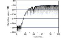 | Fig. 8. Error in the electric field intensity relative to the field maximum amplitude versus time with f = 2.0 GHz, α max = 0.075, κ max = 17, and σ ratio = 9.0. |
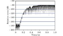 | Fig. 9. Error in the electric field intensity relative to the field’ s maximum amplitude versus time with f = 200.0 GHz, α max = 7.5, κ max = 17, and σ ratio = 9.0. |
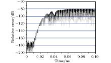 | Fig. 10. Error in the electric field intensity relative to the field maximum amplitude versus time with f = 2.0 THz, α max = 75.0, κ max = 17, and σ ratio = 9.0. |
| Table 2. Relationships of interval of α and cutoff frequency. |
Based on the relative orientation relationship between line and face on the PFCs and ECT-CFDTD method, by using the integral formulation, a conformal CPML is introduced. This method has the same numerical stability as the ECT-CFDTD method, and it can be used to truncate the open port of waveguides when using ECT-CFDTD method to simulate the wave propagation inside the waveguides. By sweeping constitutive parameters of conformal CPML, a set of numerical examinations are performed. Our numerical results show that this method is suitable for long time truncation, and the truncation error could be as low as − 80 dB.
| 1 |
|
| 2 |
|
| 3 |
|
| 4 |
|
| 5 |
|
| 6 |
|
| 7 |
|
| 8 |
|
| 9 |
|
| 10 |
|
| 11 |
|
| 12 |
|
| 13 |
|
| 14 |
|
| 15 |
|
| 16 |
|
| 17 |
|
| 18 |
|
| 19 |
|
| 20 |
|
| 21 |
|
| 22 |
|
| 23 |
|
| 24 |
|


