


Developments in laser wakefield accelerators: From single-stage to two-stage*
Cite this Article
Li Wen-Tao, Wang Wen-Tao, Liu Jian-Sheng, Wang Cheng, Zhang Zhi-Jun, Qi Rong, Yu Chang-Hai, Li Ru-Xin, Xu Zhi-Zhan. Developments in laser wakefield accelerators: From single-stage to two-stage* . Chinese Physics B, 2014, 24(1): 015205 
Permissions
Developments in laser wakefield accelerators: From single-stage to two-stage*
Corresponding author. E-mail: wwt1980@siom.ac.cn
Corresponding author. E-mail: michaeljs_liu@siom.ac.cn
Project supported by the National Natural Science Foundation of China (Grant Nos. 11127901, 11425418, and 61221064), the National Basic Research Program of China (Grant No. 2011CB808100), and the Science and Technology Talent Project of Shanghai City, China (Grant Nos. 12XD1405200 and 12ZR1451700).
Abstract
Laser wakefield accelerators (LWFAs) are compact accelerators which can produce femtosecond high-energy electron beams on a much smaller scale than the conventional radiofrequency accelerators. It is attributed to their high acceleration gradient which is about 3 orders of magnitude larger than the traditional ones. The past decade has witnessed the major breakthroughs and progress in developing the laser wakfield accelerators. To achieve the LWFAs suitable for applications, more and more attention has been paid to optimize the LWFAs for high-quality electron beams. A single-staged LWFA does not favor generating controllable electron beams beyond 1 GeV since electron injection and acceleration are coupled and cannot be independently controlled. Staged LWFAs provide a promising route to overcome this disadvantage by decoupling injection from acceleration and thus the electron-beam quality as well as the stability can be greatly improved. This paper provides an overview of the physical conceptions of the LWFA, as well as the major breakthroughs and progress in developing LWFAs from single-stage to two-stage LWFAs.
Keyword:
52.38.Kd; 41.75.Jv; 52.35.Mw; laser wakefield acceleration; staged acceleration
1. Introduction
Particle accelerators have been widely used in science, medicine, engineering, etc. The huge accelerators such as the Large Hadron Collider have been built to explore the extreme physics region. The smaller particle accelerators are the key components of many particle-beam therapy facilities in hospitals. The accelerated particles can also be converted into radiation by synchrotrons, free electron lasers (FEL), etc. High-quality electron beams are essential for these applications. Take the FEL for example, the electron beams with 1 GeV energy, 0.2% energy spread, several kiloampere (kA) current, and 1 mm· mrad emittance are needed for the soft X-ray laser output.
The acceleration gradient of the traditional accelerator which uses the conducting electrodes or electromagnetic cavity is limited by the electrical breakdown to be less than 100 MV/m. The laser wakefield accelerator (LWFA)[1] based on the plasma has been considered as the newgeneration compact particle accelerators. Its accelerating gradient[2] is on the order of E0 = cmeω p/e, where me and e are the electron rest mass and charge, ω p = (4π ne2/me)1/2 is the plasma frequency, and n is the electron density. In general experiments, n0 is usually at the 1018 cm– 3 level, and the corresponding E0 is at the 100 GV/m level. It is about 3 orders of magnitude larger than the traditional radio frequency (RF) accelerator. Compared to the kilometer-scale traditional accelerators, a centimeter-scale LWFA is capable of providing the GeV-class electron bunches, which is significant for many applications such as FEL, [3– 6] the Compton scattering, [7– 9] bremsstrahlung radiation, [10– 12] etc.[13, 14]
Great effort has been made in improving the beam quality and increasing the energy gain of the LWFA in the past decade, leading to the great progress in this field. However, a single-staged LWFA does not favor generating controllable electron beams beyond 1 GeV since electron injection and acceleration are coupled and cannot be independently controlled. Staged LWFAs provide a promising route to obtain controllable multi-GeV electron beams where the electron injection and acceleration are decoupled, and thus the electron-beam quality as well as the stability can be greatly improved.[15– 22] In this review, we shall summarize the key concepts of the LWFA and discuss the breakthroughs in both single-stage and two-stage LWFAs.
2. Physics of the LWFA
When a relativistic femtosecond laser pulse propagates in the plasma, electrons are expelled outward by its ponderomotive force, while the ions keep still due to their large mass, forming a space charge field which drags the electrons backward. For the electrons that cannot catch up with the laser pulse, they will oscillate at the plasma frequency due to the space charge force, which forms the wakefields behind the laser pulse. The group velocity (vwg) of the wakefield is zero while its phase velocity (vwp) equals the group velocity of the laser pulse (vlg) in plasma, which is lower than that in vacuum.[23]
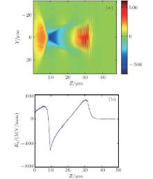
The first or second period of the wakefield is generally used for the electron acceleration. As shown in Fig. 1, each period can be separated into two parts: the acceleration region in the rear and the deceleration region in the front. In the one-dimensional (1D) regime, an electron that is released in the head of the period will slip backward with respect to the laser pulse and wakefield initially and gain energy in the acceleration region. It cannot be trapped if its initial velocity is so low that it does not gain enough energy to stop slipping out of the wake period. However, electrons with velocity higher than the phase velocity vwp can get trapped inside the wakefield and move forward with respect to it. Their acceleration process will not cease until they enter into the deceleration phase of the wakefield.[1]
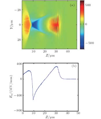 | Fig. 1. (a) The 2D image of the longitudinal acceleration field of the LWFA inside the first period. (b) The plot of the accelerating field Ez on the longitudinal axis of (a). |
Dephasing length Ld is defined as the length that the electron must travel before it slips into the decreasing phase. According to Lu’ s scaling law in 3D nonlinear regime.[24] dephasing length is

where ω is the laser frequency, and R is the blowout radius. The maximum energy gain limited by Ld is about
For example, Ld and Δ E is about 4 mm and 500 MeV respectively for the electron density np = 3.0 × 1018 cm– 3 and the normalized vector potential of laser field a = 3. The Ld and Δ E increase with the decrease of the plasma density. However, higher initial energy will be required for the electrons to be trapped since the phase velocity vwp is higher in the plasma with lower density.
3. Single-stage LWFA
The single-stage LWFA is defined as the LWFA where electrons are injected and accelerated in the same plasma region. The simplicity of this structure makes it an ideal platform for the validation of theories and the demonstration of new advocated schemes. In the past years, most of the LWFA experiments and simulations were carried out with such a simple structure, and the beam quality of the single-stage LWFA has been greatly improved. Quite a few of issues have been proposed and solved in many aspects like the matching between the plasma and the laser pulse, [25, 26] the injection scheme, [27– 31] the laser guiding, [32– 35] etc.
3.1. Matching between the plasma and the laser pulse
Most of the LWFA electron beams achieved before 2004 were the poor-quality ones with large energy spread and emittance.[36– 38] Three distinguished experiments[25, 26, 32] in 2004 made people realize that matching between the plasma and the laser pulse plays an important role in trapping and accelerating the electron beam. This matching is embodied in two aspects: (i) the matching between the plasma wavelength and the laser pulse duration; and (ii) the matching between the dephasing length and the interaction length.
Before 2004, the generation of the wakefield in most LWFA experiments relied on the self-modulation of the long laser pulse.[38, 39] Its duration was longer than the plasma wavelength so that both the injection and acceleration process of the beam occurred inside the laser pulse. The electrical and ponderomotive forces of the laser pulse would modulate the electron beam, leading to its poor quality. The beam quality can be optimized if the plasma wavelength matches with the laser pulse duration. The LWFA experiment carried out by Faure et al. in 2004[25] proved this point first. The duration and power of the laser pulse was 50 fs and 7.6 × 10¹⁸ W· cm– 2, respectively. When the plasma density was between 6 × 10¹⁸– 7.5 × 1018 cm– 3, the extremely collimated and quasi-monoenergetic electron beam with a charge of 0.5 nC and peak energy of 170 MeV was achieved. If the duration was longer than 50 fs or the plasma density was higher than 1.0 × 1019 cm– 3, the electron energy distribution became maxwellian-like with the 100% energy spread.
If the interaction length between the laser pulse and the plasma is longer than the dephasing length, the electron beam would enter the deceleration and defocusing phase of the wakefield before leaving the plasma region. This would influence both the energy spread and emittance of the beam. The importance of the matching between them was pointed out by Mangles et al.[26] in 2004. In their experiments, the plasma density was controllable between 3.0 × 1018 cm– 3 and 5.0 × 1019 cm– 3, while the laser pulse was maintained with the duration of 40 fs and the power of 2.5 × 10¹⁸ W· cm– 2. When the density was lower than 7.0 × 1018 cm– 3, no energetic electrons were observed. This was mainly because no electron has been trapped in such low density plasma. High-quality electron beams appeared when the density was between 3.0 × 1018 cm– 3 and 5.0 × 1019 cm– 3. As shown in Fig. 2, the dephasing length is longer than the interaction length in this case (red region) so that the electron beam has not entered the deceleration phase yet. When the density is higher than 3.0 × 1019 cm– 3 (blue region), the electron beam enters into the decrease phase so that its peak energy begins to decrease and its energy spread becomes 100%.
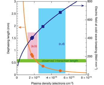 | Fig. 2. Plot of the dephasing length and the cold wave-breaking amplitude versus plasma density. The dephasing length is longer than the interaction length in the red region while shorter than it in the blue region.[26] |
3.2. Electron injection scheme
A suitable injection scheme is essential for the optimization of the beam quality. The requirement of electron injection is that the electron velocity is larger than the phase velocity of the wakefield. Many schemes such as the self-injection scheme, [27, 40, 41] the density transition injection scheme, [42– 44] the tunnel– ionization– injection scheme, [31, 45, 46] and the colliding pulse injection scheme[29, 47, 48] have been brought up to satisfy it.
The background electrons can be self-trapped when the wake breaking occurs. Similar to the traditional RF accelerator, there is also a limitation for the electric field of the nonlinear plasma wave, which is referred to as the cold relativistic wave breaking field EWB. When the wakefield amplitude approaches EWB, the plasma density in the rear becomes singular and the wave breaking occurs. The electrons can be self-trapped during this process, suppressing the further increase of the wake amplitude. The stable self-injected electron beams have been achieved experimentally recently.[41]
The density transition injection scheme is also a self-injection scheme in essence. In this scheme, a downward density transition is used to induce the local self-trapping. When a laser pulse passes through such a downward density transition, the distance between the wake phase peaks and the laser pulse would increase due to the increase of the plasma wavelength at the lower density plasma. This would decrease the phase velocity of the wake, leading to the self-trapping of the background electrons. For the density transition that extends over several hundred micrometers, [43] the energy spread of the trapped beam is usually large because the injection process may last a long period. Using a sharp downward density transition on the order of the plasma wavelength, [30, 42, 49] by contrast, we can produce the electron beam with much smaller energy spread. In 2010, Schmid et at.[30] employed a sharp downward density transition for the electron injection. The transition was formed by inserting a knife edge into a supersonic gas jet. During the short pass of the transition, the plasma wavelength increases greatly from the high-density region to the low-density one. A fraction of the background electrons were rephased into the rear of the wake due to the abrupt increase of the plasma wavelength. The electron beam with tunable energy between 15 and 25 MeV and the energy spread about 4% were achieved. The shot-to-shot fluctuation, the energy spread, and the divergence of the electron beams in the sharp density-transition injection scheme are smaller than those of the self-injection case.
For the tunnelionization injection scheme, the mixed plasma which consists of the low-Z atoms and the high-Z atoms, such as helium and oxygen, are generally used. The background electrons are ionized from the low-Z atoms and the L-shell electrons of the high-Z atoms. The trapped electrons are the K-shell ones of the high-Z atoms, which are tunnel ionized at the peak of the laser pulse. They are very easy to be trapped since they are released inside the wakefield.
In 2010, Clayton et al.[31] achieved the electron beam with the maximum energy gain extending up to 1.45 GeV by combining the concepts of matched beam, self-guided propagation, and tunnel– ionization injection. The 60 fs, 110 TW laser pulse was self-guided over a 1.3-cm-long gas cell with a density of 1.5 × 1018 cm– 3. The mixture gas of He and CO2 was employed in the experiments. 3D particle-in-cell (PIC) simulations indicated that these accelerated electrons were the K-shell electrons of oxygen. However, due to the continuous injection of this scheme, the energy spread of the beam was 100%.
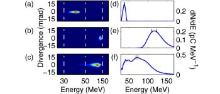
Several schemes[50, 51] that control the laser pulse evolution in the plasma have been proposed to improve the beam quality of the tunnel– ionization– injection scheme. For example, Xia et al.[50] proposed to shorten the injection process by controlling the self-focusing of the laser pulse. With the mixture gas density of 7 × 1018 cm– 3, the energy spread of electron beam was decreased from 100% to 24% when the laser intensity was decreased from 9 × 10¹⁸ W· cm– 2 to 6 × 10¹⁸ W· cm– 2 (Fig. 3). Meanwhile, the electron beam energy and charge can also be controlled. The distance over which the laser intensity was higher than the threshold of the tunnel ionization was shortened by the lower initial laser intensity, so that the quasi-monoenergetic beam was produced.
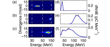 | Fig. 3. Energy spectra of the electron beams when the laser intensity is (a, d) 6 × 10¹⁸ W· cm– 2, (b, e) 7.9 × 10¹⁸ W· cm– 2, and (c, f) 9 × 10¹⁸ W· cm– 2.[50] |
Schemes that use the extra laser pulse to trigger the ionization injection process inside the wakefield were demonstrated via the PIC simulations.[52– 55] Bourgeois et al.[53] proposed to control the electron injection into the second period of the quasilinear wakefield by a collinear injection laser pulse with a certain delay after the driving laser pulse. Yu et al.[54] proposed a scheme that uses two lasers of different colors for generating electron beams with ultralow emittance (∼ 10– 8 mrad).
For the colliding pulse injection scheme, [29, 56] one or two more laser pulses are used to induce the injection process by pre-accelerating electrons through the beatwave formed by two colliding laser pulses. Similar to the tunnel– ionization– injection scheme, the electrons are pre-accelerated inside the wakefield, so that they are also very easy to be trapped. This scheme has been proved by Faure et al.[29] to have great advantage on the controllability of the beam energy and charge.
3.3. Laser guiding
For the plasma with a large amplitude electromagnetic wave inside, its index of refraction can be expressed as

where n(r) is the plasma density, and γ (r)≅ (1+ a(r)2)1/2 is the relativistic factor of the background electrons.[2] Both factors can be used to modify the profile η r(r) transversely so that laser pulse can be guided in the plasma.
For the laser pulse with intensity peaks on axis, the index of refraction is highest on axis and decreases radially off axis. The relativistic self-focusing occurs naturally when the laser power is higher than the critical power Pc(GW) ≈ 17.4(ω /ω p0)2. This condition was satisfied in many experiments and the well-matched laser pulse could even be self-guided for a long distance (∼ cm).[57– 60] During the self-guiding process, the laser intensity may increase significantly due to the self-focusing effect. Laser pulse that is too weak for the electron injection can be self-focused beyond the intensity threshold of the self-injection or ionization injection. The first experiment of long-distance self-guiding with a laser power greater than 200 TW was carried out by Kneip et al.[34] in 2009. The laser pulse was self-guided for 1 cm and more than 30% of the initial laser energy was unchanged. Electrons were self-injected with this self-focused laser pulse and 0.8 GeV energy gain was achieved.
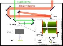
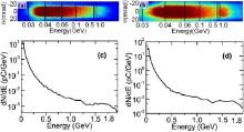
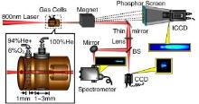
The density channel with a parabolic transverse density profile n(r) which is minimum on axis can also be used to guide the laser pulse. The methods to create such a channel include the igniter– heater method, [32, 61] the discharge method for the gas-filled capillary[33] or ablative capillary, [62] etc. In the experiments carried out by Geddes in 2004, [32] a 1.7-mm channel was formed by two laser pulses (heater pulse, igniter pulse) that heat and expand the plasma on axis. This channel-guided LWFA produced 86 MeV electron beams with energy spread of ± 2% and charge of 320 pC. A much longer channel (∼ 3.3 cm) was produced by Leemans et al.[33] in 2006 with the discharge method. A discharge was triggered through the 3.3-cm-long sapphire capillary waveguide filled with hydrogen gas. The energy transmission of 40-TW laser pulse was about 65%. The self-injected beam with 1 GeV energy gain was achieved. The discharge method for the 4-cm-long ablative capillary was demonstrated by Lu et al.[62] in 2011. The discharge was triggered by a Nd:YAG laser pulse that was focused onto a copper needle inside the capillary (Fig. 4). The radial distribution of the plasma density was measured to be a parabolic profile and the energy transmission was about 55%. Electrons were ionization injected and accelerated up to 1.8 GeV (Fig. 5) with the oxygen-containing acrylic resin capillary.
 | Fig. 4. Schematic experimental setup of the ablative capillary discharge waveguide LWFA.[62] (a)– (b) Raw data recorded by the IP; (c)– (d) integrated spectra. |
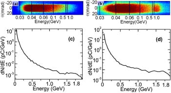 | Fig. 5. Measured single-shot electron beam energy spectra.[62] (a)– (b) Raw data recorded by the IP; (c)– (d) integrated spectra. |
3.4. Phase-locking acceleration
Although the maximum acceleration gradient of the LWFA is three orders of magnitude larger than the RF accelerator, its gradient decreases sharply during the dephasing process. The high acceleration gradient can be maintained if the beam phase of the wakefield is locked during the acceleration process. The energy gain limited by the dephasing length can also be greatly increased.
Plasma tapering[63, 64] has been proposed to phase-lock the electron beam in the wakefield. The plasma density is increased as the electrons slip forward with respect to the laser pulse. Since the plasma wavelength is inversely related to the plasma density, the beam phase inside the wake can be possibly maintained (phase locking) if the plasma density is optimally designed. The explicit expression for the density taper[65] has been derived in the linear regime with a2 < 1. The optimized energy gain without the consideration of laser evolution can be much larger than the maximum energy gain limited by dephasing length. In the nonlinear regime, however, the effect of tapered plasma is greatly limited by the relativistic prolonging of the plasma wavelength.[66]
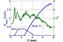
In 2014, Li et al.[67] demonstrated a phase-locking dynamics of the LWFA with an intensity-decaying laser pulse. An electron beam with the maximum energy up to 1.8 GeV, which is much higher than the dephasing limitation was experimentally obtained. The PIC simulations indicated that the electron beam acceleration was accompanied with the laser intensity decreasing process (Fig. 6). Since the nonlinear plasma wavelength is proportional to the laser intensity, the plasma wavelength was also shortened in this process (Fig. 7(a)), which contributed to the phase locking effect of the beam in the wakefield. Compared to the dephasing case that electron beam entered into the middle of the wake (Fig. 7(b)), the phase was locked for the beam which was accompanied with an intensity-decaying laser pulse (Fig. 7(a)). The laser intensity evolution for the perfect phase-locking acceleration in the uniform plasma was also derived. This scheme may be very important for the GeV or even TeV range LWFA because the decaying of the laser intensity is unavoidable due to the pump depletion effect in the long distance propagation.
 | Fig. 6. Evolutions of the normalized amplitude a (solid green line) and the peak energy of the phase-locked electron beam (solid blue line) as a function of the distance z (mm).[67] |
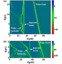
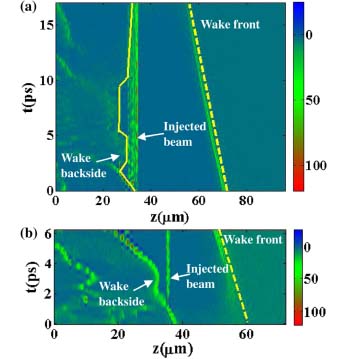 | Fig. 7. Spatial and temporal evolution of the electron density on the longitudinal axis of the wake along the laser propagation in the moving simulation box. (a) Phase-locking case. (b) Dephasing case.[67] |
3.5. Single-stage LWFA with petawatt laser facility
As mentioned before, the final energy gain of the LWFA is generally limited by the dephasing length. Without the phase-locking effect, the electron density on the 1017 cm– 3 level is needed for the energy gain well beyond 1 GeV. Petawatt (PW) ultrashort laser facility is necessary for the electron injection and laser guiding in such a region.[68]
In 2013, Wang et al.[69] demonstrated the 2 GeV quasi-monoenergetic electron acceleration with the Texas Petawatt laser. A 7-cm-long gas cell filled with pure helium was used in the experiments. When the plasma density was adjusted between 4 × 1017 cm– 3 and 6 × 1017 cm– 3, a 2-GeV electron beam with energy spread about 10% and divergence of 0.6 mrad was achieved. The PIC simulations showed that energy gain up to 10 GeV was possible if the focusing quality of this laser facility could be further optimized.
4. Two-stage LWFA
Although the LWFA can provide the accelerating gradient up to ∼ 100 GV/m, its final energy gain of one stage is generally limited by the dephasing length, which is only about several hundreds of MeV at the density of 1018 cm– 3 level. Since electron injection and acceleration are coupled and cannot be independently controlled in a single-stage LWFA, it does not favor generating controllable electron beams beyond 1 GeV. The cascaded electron acceleration scheme[15, 17– 21] has been brought up to solve this problem, just like the accelerating stages in the traditional electron accelerators which are hundreds or thousands of meters long. The key issues for efficiently obtaining high-quality e-beams in the cascaded LWFA schemes rely on the control and optimization of the electron seeding phase relative to the accelerating field in the next stage. Furthermore, the matched self-guided propagation in the second LWFA has also to be satisfied. The ability to stage together multi-LWFAs is of vital importance for eventually building practical laser wakefield accelerators of 10 GeV class and higher energy.
4.1. Two-stage LWFA based on ionization injection scheme
In 2011, Liu et al.[17] first realized a two-stage acceleration scheme based on ionization-induced injection. In this all-optical cascaded LWFA, two different stages were employed (Fig. 8). Electrons were tunnel ionization injected in the first stage of a 1-mm-long He/O2 mixture gas. At the density of 7 × 1018 cm– 3, the beam energy of the firststage LWFA was about 40 MeV (Figs. 9(a)– 9(c)). This low-energy beam with the Maxwellian spectrum was further seeded into a 1-mm-long acceleration stage of the pure He gas (2.5 × 1018 cm– 3). When the laser power was 48 TW, its peak energy was increased to 83 MeV, and the energy spread was decreased to 9% (Figs. 9(d) and 9(e)). The peak energy was further increased to about 200 MeV by increasing the thickness of the second gas cell to 3 mm (Figs. 10(a) and 10(b)). A 0.8-GeV quasimonoenergetic electron beam with the energy spread of 25% was achieved (Fig. 10(c)) when the driving laser power was 45 TW.
 | Fig. 8. Schematic of experimental setup for the cascaded LWFA.[17] |
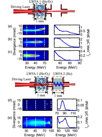 | Fig. 9. Single-shot electron beam spectra from the single-stage LWFA (a)– (c) and the two-stage LWFA (d)– (e). The thickness of the second stage is 1 mm.[17] |
 | Fig. 10. Single-shot electron beam spectra from the two-stage LWFA with 3-mm-thick second stage. The laser power on the target is (a) 50 TW, (b) 48 TW, and (c) 45 TW.[17] |
The similar scheme was also demonstrated by Pollock et al.[18] The first stage was a 4-mm gas cell filled with the mixture gas of He and N2. Its energy spread was large due to the continuous ionization-induced injection. By adding the second 8-mm-long gas cell with the pure He, the peak energy was increased from about 120 MeV to 460 MeV, and the energy spread was reduced to 5%. Unlike the experiment carried out by Liu, the electron densities of the two stages in this experiment were similar (3 × 1018 cm– 3), which may be beneficial for the maintaining of the beam phase as seeded into the wakefield of the second stage.
4.2. Two-stage LWFA based on density transition injection scheme
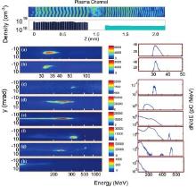
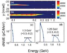
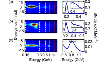
In addition to the two-stage LWFA with the ionization-induced injection scheme, the one with the density transition injection scheme was also proposed and demonstrated.[20, 21, 70] In the experiments carried out by Wang et al., [70] the seeding phase of electrons into the second stage was controlled and optimized by controlling the densities of the two stages. When the first stage (9 × 1018 cm– 3) was used alone in the experiments, the low-energy beams with the peak energy of about 30 MeV and the energy spread of about 15% were obtained (Figs. 11(a) and 11(b)). The energy gain was increased to about 310 MeV when the second stage was filled with the low density gas (5 × 1018 cm– 3) (Fig. 11(c)). The energy spread was also decreased to about 10%. As the plasma density was decreased to 3.5 × 10¹⁸– 4 × 1018 cm– 3, the energy gain was decreased to 200 MeV while the energy spread was increased to 50% (Figs. 11(d) and 11(e)). This was mainly because the seeding phase which was at the bubble base when the density was 5 × 1018 cm– 3 was moved toward the middle of the bubble. Electrons were inefficiently accelerated in this case. When the density was further decreased to 2.5 × 1018 cm– 3 (Figs. 11(f) and 11(g)), the bubble size in the second stage would almost be doubled so that the trapped beam in the second period of the wakefield in the first stage were seeded into the first period in the second stage. Due to such an optimization of the seeding phase, the beams with energy of 0.53 GeV and energy spread of 3% were achieved in this case. By lengthening the second stage from 2 mm to 5 mm, the peak energy of the beam was increased to 1.3 GeV (Fig. 12). The underlying mechanism was demonstrated by Deng et al.[21] through the PIC simulations.
 | Fig. 11. Electron beam spectra from the single-stage LWFA (a)– (b) and the two-stage LWFA (c)– (h). The plasma density of the second stage is (c) 5 × 1018 cm– 3, (d) 4 × 1018 cm– 3, (e) 3.5 × 1018 cm– 3, (f)– (g) 2.5 × 1018 cm– 3, and (h) 2 × 1018 cm– 3.[70] |
4.3. Two-stage LWFA with petawatt laser facility
The cascaded electron acceleration with PW laser pulses was also carried out and the energy gain up to 3 GeV is achieved in 2013 by Kim et al.[22] A 4-mm-long gas cell with pure helium of 2 × 1018 cm– 3 was used in the injection stage and a 10-mm-long gas cell with pure helium of 0.8 × 1018 cm– 3 was used in the acceleration stage. The 400-MeV electron beam was achieved from the injection stage alone, and the energy gain was further increased to 3 GeV by adding the acceleration stage. No electron was accelerated from the acceleration stage alone at this density. The divergence and charge of the beam was about 4 mrad and 80 pC, respectively
5. Summary and outlook
This paper briefly reviews the recent remarkable progresses on both single-stage LWFA and two-stage LWFA. The experimental energy spread has been decreased to less than 3%, and the energy gain has been increased up to 3 GeV. Although there is still a long way to go for applications, for example, the quality of the LWFA electron beam is still not good enough to replace the traditional electron beam in the FEL, more and more exciting progress has been achieved by different research groups all over the world. Recently, the electron beams with energy up to 4.2 GeV, 6% energy spread, and 0.3 mrad divergence have been produced by Leemans et al with a 0.3 PW laser facility. Nevertheless, the quality and stability of the LWFA electron beams can be greatly improved if the design of the two-stage LWFA is further optimized, for example, the optimization of electron injection, seeding phase in the second stage, and the long-distance stable propagation of the laser pulse. The ability to stage together multi-LWFAs is of vital importance for eventually building practical laser wakefield accelerators of high-energy electron beams beyond 10 GeV, whereby the electrons are repeatedly accelerated by the laser field in a manner similar to radio-frequency accelerators.
Reference
| 1 |
|
| 2 |
|
| 3 |
|
| 4 |
|
| 5 |
|
| 6 |
|
| 7 |
|
| 8 |
|
| 9 |
|
| 10 |
|
| 11 |
|
| 12 |
|
| 13 |
|
| 14 |
|
| 15 |
|
| 16 |
|
| 17 |
|
| 18 |
|
| 19 |
|
| 20 |
|
| 21 |
|
| 22 |
|
| 23 |
|
| 24 |
|
| 25 |
|
| 26 |
|
| 27 |
|
| 28 |
|
| 29 |
|
| 30 |
|
| 31 |
|
| 32 |
|
| 33 |
|
| 34 |
|
| 35 |
|
| 36 |
|
| 37 |
|
| 38 |
|
| 39 |
|
| 40 |
|
| 41 |
|
| 42 |
|
| 43 |
|
| 44 |
|
| 45 |
|
| 46 |
|
| 47 |
|
| 48 |
|
| 49 |
|
| 50 |
|
| 51 |
|
| 52 |
|
| 53 |
|
| 54 |
|
| 55 |
|
| 56 |
|
| 57 |
|
| 58 |
|
| 59 |
|
| 60 |
|
| 61 |
|
| 62 |
|
| 63 |
|
| 64 |
|
| 65 |
|
| 66 |
|
| 67 |
|
| 68 |
|
| 69 |
|
| 70 |
|