


Picosecond pulses compression at 1053-nm center wavelength by using a gas-filled hollow-core fiber compressor*
Cite this Article
Huang Zhi-Yuan, Wang Ding, Leng Yu-Xin, Dai Ye. Picosecond pulses compression at 1053-nm center wavelength by using a gas-filled hollow-core fiber compressor* . Chinese Physics B, 2014, 24(1): 014212 
Permissions
Picosecond pulses compression at 1053-nm center wavelength by using a gas-filled hollow-core fiber compressor*
Corresponding author. E-mail: lengyuxin@siom.ac.cn
Corresponding author. E-mail: yedai@shu.edu.cn
Project supported by the National Natural Science Foundation of China (Grant Nos. 11204328, 61221064, 61078037, 11127901, and 11134010), the National Basic Research Program of China (Grant No. 2011CB808101), the Commission of Science and Technology of Shanghai, China (Grant No. 12dz1100700), the Natural Science Foundation of Shanghai, China (Grant No. 13ZR1414800), and the International Science and Technology Cooperation Program of China (Grant No. 2011DFA11300).
Abstract
We theoretically study the nonlinear compression of picosecond pulses with 10-mJ of input energy at the 1053-nm center wavelength by using a one-meter-long gas-filled hollow-core fiber (HCF) compressor and considering the third-order dispersion (TOD) effect. It is found that when the input pulse is about 1 ps/10 mJ, it can be compressed down to less than 20 fs with a high transmission efficiency. The gas for optimal compression is krypton gas which is filled in a HCF with a 400-μm inner diameter. When the input pulse duration is increased to 5 ps, it can also be compressed down to less than 100 fs efficiently under proper conditions. The results show that the TOD effect has little impact on picosecond pulse compression and the HCF compressor can be applied on compressing picosecond pulses efficiently with a high compression ratio, which will benefit the research of high-field laser physics.
Keyword:
42.65.Re; 42.65.Jx; 42.81.Qb; picosecond pulses; third-order dispersion; hollow-core fiber; spectrum broadening
1. Introduction
The chirped pulse amplification (CPA) technique has made remarkable advances to the generation of ultrashort laser pulses with extremely high-peak power.[1] The powerful CPA lasers have been used in fundamental research areas, such as the generation of bright X-ray, the fast ignition approach of laser fusion, relativistic particle acceleration, experimental quantum electrodynamics, and laboratory astrophysics.[2, 3, 4] Based on laser materials, such as Nd:glass, the technology of high power and short pulse lasers near 1 μ m is mature. Limited by the narrower gain bandwidth of Nd:glass, the pulse duration near 1 micron is generally in the picosecond level, [5] and the pulse has high-order dispersion.[6]
To obtain shorter pulse durations, external-cavity spectral broadening and pulse compression techniques are necessary.[7] Nonlinear propagation through a noble gas-filled hollow-core fiber (HCF) is a widely used technique to acquire efficient spectral broadening in the visible and near-infrared spectral range.[8– 11] Compared with the pulse compression using traditional optical fibers of bulk materials, the hollow-core fiber improves the output energy level to the milli-joule while preserving the few-cycle duration.[12] In addition, the confinement of the dielectric waveguide ensures spatially uniform broadening and an excellent output beam profile.[13] The HCF compressor is now mainly used to compress femtosecond multi-optical-cycle pulses to few-cycle pulses. However, as far as we know, few simulations have been carried out for picosecond pulses compression in the mJ energy level in the 1-micron pulse duration region by using a HCF compressor.
In this paper, we theoretically study the nonlinear compression of the picosecond pulses with 10-mJ input energy at 1053-nm center wavelength by using a gas-filled hollow-core fiber and considering the third-order dispersion (TOD) effect. This paper is organized as follows. Section 2 describes the schematic layout of the CPA laser and the model of nonlinear compression with a gas-filled HCF. In Section 3, we first compare the results obtained with different types of noble gases, gas pressures within the fiber, and inner diameters of the fiber to obtain the optimal compression parameters. The spectral phases before and after chirp compensation are analyzed, and the process of chirp compensation is also given. Then, the spectral intensity evolutions of the pulses by increasing the gas pressures and the distances of the HCF are presented. Next, we show the nonlinear compression of the picosecond pulses with TOD by using a krypton gas-filled HCF compressor. Finally, we give the compression results when the initial pulse duration is increased to 5 ps. The paper ends with a conclusion in Section 4.
2. The model of CPA laser and spectral broadening
The 10-Hz, 10-mJ CPA laser consists of a 20-kHz fiber laser operating at 1.03– 1.06 μ m, a grating stretcher, a pulse selector, a regenerative amplifier, a Nd:glass amplifier working at 10 Hz, and a grating compressor, as shown in Fig. 1. The seed pulses of CPA come from the fiber laser and are characterized by a few nanometers of spectrum width and hundreds of picosecond of pulse width. Laser pulses from the 20-kHz fiber laser are stretched to > 1 ns by a grating stretcher. Then the laser pulses pass through a pulse selector to modulate at 10 Hz and are amplified in the regenerative amplifier and the Nd:glass amplifier such that their energies reach 15 mJ.[14] After the grating compressor, the laser pulses have 10-mJ energy and 1– 10 ps pulse duration at 1053 nm. Although the second-order dispersion is compensated easily, the high-order dispersion still exists in the output pulse. High-order dispersion comes from two places, one is the amplifiers and the other is the fiber laser.
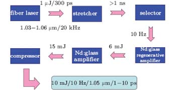 | Fig. 1. Schematic layout of the 10-Hz 10-mJ CPA laser. |
In the CPA laser, Nd:glass is used in the amplifiers, and the total length of Nd:glass is 3– 5 m. The Sellmeier equation for Nd:glass is given as[15]
 |
n is the refractive index, and λ is the wavelength of light in μ m. We obtain the dispersion including the second-order dispersion of 0.1198 ps2, the third-order dispersion of 2.0362× 10− 4 ps3, and the fourth-order dispersion of -2.2275× 10− 7 ps3 by the equation in the five-meter-long Nd:glass at a center wavelength of 1053 nm. It should be noted that the high-order dispersion within the output pulse is not noticeable in the Nd:glass compared with the dispersion from the fiber laser. For simplicity, the output pulse with high-order dispersion can be expressed as
 |
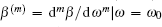
where U0 is Gaussian pulse without chirp, ω is the angular frequency of the pulse, F represents Fourier transform and F− 1 is the inverse Fourier transform, TOD and FOD represent the third-order and the fourth-order dispersion, respectively.
In order to achieve pulse durations below tens of femtoseconds, spectral broadening is necessary. Moreover, in comparison with TOD, the fourth-order and higher-order dispersion is quite small, thus we just consider the influence of TOD based on the process of spectral broadening in the HCF.
The spectral broadening is achieved in a one-meter-long noble gas-filled HCF based on the self-phase modulation effect (SPM). Here, we use a single HCF with static gas pressure. The envelope E(z, t, r), assumed to be slowly varying in time, evolves along the propagation axis z according to the propagation of the fundamental mode equation[16, 17]
 |
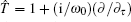
where the linear operator 


 |
where ionization rate W is obtained by the Perelomov, Popov, and Terent'ev (PPT) theory.[18]
3. Numerical results and analysis
In order to obtain the optimal compression parameters, we simulate the nonlinear compression of picosecond pulses without considering the TOD at 1053-nm center wavelength by using different types of noble gas, gas pressures within the fiber, and inner diameters of the fiber.
We first use the neon gas-filled HCF with a 250-μ m inner diameter to compress the picosecond pulses with 1-ps pulse duration and 10-mJ input energy at the gas pressure of 30 bar. Figures 2(a) and 2(b) show the output pulse temporal profile and spectral intensity after compression with optimal chirp compensation, respectively. The duration (full width at half maximum, FWHM) of the pulse is 35 fs and the energy transmittance is about 78%. To improve the efficiency of the pulse compression, we use argon gas, krypton gas, and xenon gas with high nonlinear parameters to couple into the fiber, and the inner diameter of 400 μ m is employed to obtain the large energy transmittance. Figures 2(c) and 2(e) show the pulse temporal profiles with the optimal compensation for argon gas at 10 bar and krypton gas at 6 bar, respectively, and the FWHMs of the pulses are 21 fs and 12 fs, respectively. In addition, the energy transmittance increases to about 90%. The output spectral intensities are given in Figs. 2(d) and 2(f). In addition, the simulation results of pulse compression using xenon gas at 3-bar pressure are shown in Figs. 2(g) and 2(h), from which we can see that the pulse has a breakup, and a large peak is developed in the corresponding spectrum from 0.9 μ m to 1 μ m. In Table 1, we can notice that the xenon gas has a lower ionization potential and a higher nonlinear refractive index compared with the other gases; these properties lead to this phenomenon. In comparison with those using neon gas and argon gas, the pulse has the higher compression ratio when employing the lower gas pressure by using a krypton gas-filled HCF, thus the krypton gas is the better choice to compress the picosecond pulses.
| Table 1. The ionization potential and nonlinear refractive index with 1-bar pressure at 1053 nm of the noble gas. |
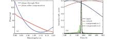
Moreover, figure 3(a) gives the spectral phases of the output pulses before and after the chirp compensation for krypton gas at 6-bar gas pressure. Before the compensation of the pulse, the fast modulations are observed around the center wavelength, which is caused by the spectral broadening due to the SPM effect.[19, 20, 21, 22, 23] After the chirp compensation, [24] the spectral phase performs like a straight line. However, in the central region, the ripple-shape spectral phase including high-order phase terms is observed and these high-order phase terms are difficult to compensate simply by using the chirped mirrors. Besides, in Figs. 2(a), 2(c), and 2(e), the compressed pulses shift toward the positive side (time > 0) with different types of noble gas and gas pressures. This phenomenon is caused by the self-steeping effect and chirp compensation, as shown in Fig. 3(b), where the blue solid curve represents the input pulse and the position of the center of the pulse is zero, the red dash curve is the output pulse without compensation, it shifts toward right side about 300 fs, while the green and black dotted curves, with compensation of – 0.00175 ps2, – 0.00193 ps2, and 0.0000017 ps3, respectively, their positions are between 100 fs and 200 fs. The TOD compensation is used to decrease the wing based on the leading edge of the pulse.
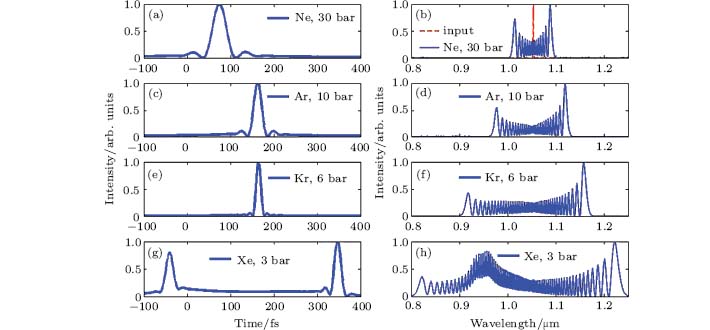 | Fig. 2. The output pulses temporal profiles ((a), (c), (e), (g)) and spectral intensities ((b), (d), (f), (h)) after compression with optimal chirp compensation for different types of noble gas and gas pressures, respectively. (a) and (b) neon gas at 30 bar, (c) and (d) argon gas at 10 bar, (e) and (f) krypton gas at 6 bar, (g) and (h) xenon gas at 3 bar. The red dash curve represents the initial pulse spectrum. |
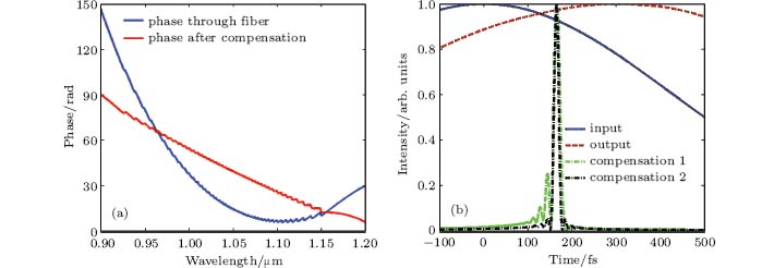 | Fig. 3. (a) The spectral phases of the pulses passing through fiber (blue solid curve) and after compensation (red solid curve) using krypton gas at the pressure of 6 bar. (b) The pulses temporal profiles with different chirp compensation using krypton gas at the pressure of 6 bar, the blue solid curve, red dash curve, green and black dotted curves represent the input pulse, the output pulse without compensation, and the cases with compensation of – 0.00175 ps2, – 0.00193 ps2, and 0.0000017 ps3, respectively. |
Next, we simulate the nonlinear compression of the picosecond pulses by using a krypton gas-filled HCF at different gas pressures ranging from 3 bar to 7 bar, as shown in Figs. 4(a) and 4(c). The corresponding FWHMs are 23 fs, 18 fs, 15 fs, 12 fs, and 11 fs after the optimal GDD and TOD compensation by using chirped mirrors, and the pulses obtain the excellent profiles. Figures 4(b) and 4(d) show spectral intensity evolutions with the increase of the gas pressures and the distances of the fiber, respectively. When increasing the gas pressures, we can see a wider and red-shift spectrum clearly though its intensity decreases. Besides, a symmetric spectrum broadening appears due to the SPM effect. In this simulation, the pulses have a better compression ratio when the gas pressures are set to 6 bar and 7 bar.
The simulation results show that krypton gas with a high nonlinear parameter is the optimal compression gas, the inner diameter of 400 μ m improves the energy transmittance, and gas pressure is set to about 7 bar for the initial pulse with a 1-ps pulse duration and 10-mJ input energy at the center wavelength of 1053 nm. Figures 5(a) and 5(c) are the input pulses profiles with TOD from 0.1 ps3 to 0.6 ps3, and the output pulse profiles after the optimal compensation by using the krypton gas-filled HCF are shown in Figs. 5(b) and 5(d). The initial pulse durations are 1.035 ps, 1.098 ps, 1.160 ps, 1.217 ps, 1.270 ps, and 1.138 ps, and the output pulse durations after compensation are 12 fs, 12 fs, 12 fs, 13 fs, 15 fs, and 14 fs (the values were obtained by rounding the decimal fraction). Figures 5(a) and 5(c) show that the main peak of the pulses shifts toward the positive side severely and the trailing edges of the pulses have larger oscillatory structures with the increase of the TOD. Moreover, the output pulses after the optimal compensation in Fig. 5(b) obtain the better wings compared with the pulses in Fig. 5(d), it is caused by different TOD effects. In addition, it is obvious that the pulse profiles shift toward the right side of the time axis more when the pulses have the large TOD; this is due to the different optimal chirp compensation and self-steeping effect. Besides, the influence of the self-steeping effect is decided by the gas pressures within the fiber, the pulse durations, and the TOD effect.
 | Fig. 4. The output pulse temporal profiles at different gas pressures from 3 bar to 7 bar ((a) and (c)) and spectral intensity evolutions with increasing gas pressures and the distances of the fiber ((b) and (d)) by using a krypton gas-filled HCF, respectively. |
 | Fig. 5. The input pulse temporal profiles ((a) and (c)) and the output pulse profiles ((b) and (d)) after compression with optimal chirp compensation at different TOD from 0.1 ps3 to 0.6 ps3, respectively. |
Now, we turn to the case in which the pulse width increases to 5 ps. Figure 6(a) shows the pulse profiles after nonlinear compression by using a krypton gas-filled HCF. The blue solid curve represents the case with 10-mJ input energy at 20 bar, the red dash curve represents the case with 30 mJ input energy at 10 bar, and the pulse durations are 100 fs and 67 fs, respectively. The corresponding spectral intensities are given in Fig. 6(b). It is obvious that the pulse with an excellent temporal profile and tens of femtoseconds of pulse width is obtained by using the krypton gas-filled HCF compressor for the picosecond pulses.
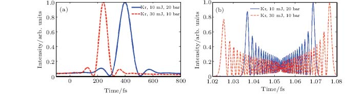 | Fig. 6. The output pulse temporal profiles (a) and spectral intensities (b) after compression with optimal chirp compensation for krypton gas with different gas pressures and input energies, respectively. The blue solid curves represent the case with 10-mJ input energy at 20 bar pressure, and the red dash curves are the case with 30-mJ input energy at 10 bar pressure. |
6. Conclusion
In conclusion, we have simulated the nonlinear compression of picosecond pulses with 10-mJ input energy at 1053-nm center wavelength based on a one-meter-long gas-filled HCF compressor. The gas for optimal compression is krypton gas which is filled in a HCF with a 400-μ m inner diameter. By using the krypton gas-filled HCF, the 1053-nm laser pulses with excellent temporal profiles and pulse width below 20 fs were obtained. When the initial pulse duration is increased to 5 ps, the pulse duration can also be compressed down to less than 100 fs efficiently with the proper parameters. The results show that the HCF compressor can be used to compress picosecond pulses with TOD efficiently with a high compression ratio, which will be useful for the research of high-field laser physics.
Reference
| 1 |
|
| 2 |
|
| 3 |
|
| 4 |
|
| 5 |
|
| 6 |
|
| 7 |
|
| 8 |
|
| 9 |
|
| 10 |
|
| 11 |
|
| 12 |
|
| 13 |
|
| 14 |
|
| 15 |
|
| 16 |
|
| 17 |
|
| 18 |
|
| 19 |
|
| 20 |
|
| 21 |
|
| 22 |
|
| 23 |
|
| 24 |
|