Design and test of the microwave cavity in an optically-pumped Rubidium beam frequency standard*
Cite this Article
Liu Chang, Wang Yan-Hui. Design and test of the microwave cavity in an optically-pumped Rubidium beam frequency standard* . Chinese Physics B, 2014, 24(1): 010602 
Permissions
Design and test of the microwave cavity in an optically-pumped Rubidium beam frequency standard*
Corresponding author. E-mail: wangyanhui@pku.edu.cn
Project supported by the National Natural Science Foundation of China (Grant No. 11174015).
Abstract
We are developing a compact rubidium atomic beam frequency standard with optical pumping and detection. The cavity for microwave interrogation is an important part of the clock. The cavity in our design is a Ramsey-type, E-bend one, which is the same as the conventional method in most cesium beam clocks. Requirements for the design are proposed based on the frequency shift associated with the cavity. The basic structure of the cavity is given by theoretical analysis and detailed dimensions are determined by means of electromagnetic field simulation with the help of commercial software. The cavity is manufactured and fabricated successfully. The preliminary test result of the cavity is given, which is in good agreement with the simulation. The resonant frequency is 6.835 GHz, equal to the clock transition frequency of87Rb, and the loaded quality factor is 500. These values are adjustable with posts outside the cavity. Estimations on the Ramsey line width and several frequency shifts are made.
Keyword:
06.30.Ft; 41.20.Jb; 42.62.Eh; rubidium beam clock; optical pumping; microwave cavity; frequency shift
1. Introduction
1.1. Optically-pumped rubidium beam clock
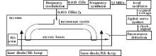
Cesium beam frequency standards employing magnetic selection have good performance in time keeping and other applications.[1] The performance of these devices is usually limited by the shot noise of the beam. An optical pumping method, which increases the utilization efficiency of atoms, helps to improve the short-term stability.[2– 4] The ground-state hyperfine transition of rubidium isotope 87Rb also acts as a frequency standard. Rubidium vapor cell frequency standards are widely studied and applied.[5] Certainly, rubidium is suitable for the atomic source of beam tubes.[6, 7] As rubidium is lighter than cesium, more and faster atoms are emitted from the oven at the same oven temperature. We are developing a compact, free-running optically-pumped rubidium beam clock, which is illustrated in Fig. 1. To avoid the mislocking problem of lasers, we prepare rubidium lamps as an alternative light source.[8] However, as the narrow line width of the laser helps to reduce detection noise, the laser is the first choice in this experiment.
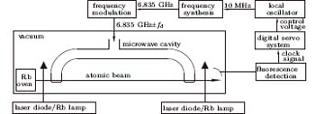 | Fig. 1. Physics package and servo circuits of the optically-pumped rubidium beam frequency standard. fd is the modulation depth of the frequency modulation. |
1.2. Microwave cavity
The microwave cavity in atomic beam frequency standards provides a standing wave for interaction between atoms and electromagnetic field, minimizing first-order Doppler shift. Generally in a frequency standard, a long interaction time means a narrow line width. The interaction time in a beam device depends on both the atom velocity and the cavity length. The most probable velocity α is dependent on the oven temperature T and atomic mass m, as
 |
where kb is the Boltzmann constant. As can be calculated, the most probable velocity of 87Rb atoms is 270 m/s assuming an oven temperature of 373 K. Lowering the oven temperature is not an effective method to narrow the line width, for it decreases the atomic beam intensity and affects the signal to noise (S/N) ratio. An alternative way is to increase the cavity length. However, uniformity of the magnetic field is hard to guarantee within a long cavity. To solve this problem, a Ramsey-type U-shape cavity, first presented by Ramsey in 1955, [9] is usually deployed in a beam device, providing two short interaction regions and a long drift distance without an oscillating field. The line width of the Ramsey fringe is reciprocal to the drift distance, which can be made very long, sometimes more than one meter in laboratory frequency standard. Works on the microwave cavity for magnetically selected cesium beam clocks were reported.[10– 12] Cavity design for rubidium fountain frequency standard was reported, [13] where the cavity is a cylinder one and atoms pass the cavity twice. As far as we know, there is no report on the microwave cavity in an optically-pumped rubidium beam frequency standard. We design and manufacture a low-quality-factor, compact and dismountable microwave cavity for our rubidium beam frequency standard. A previous design of our rubidium beam cavity was reported.[14] We have changed the cross section of the waveguide from the previous design to reduce the wave reflection, which means modifications on many dimensions. We describe in detail the tunning device of the cavity. The experimental samples of the cavity are successfully manufactured and mounted. The parameters of the cavity are measured to verify the design feasibility.
2. Theoretical analysis
2.1. Related frequency shift
Several frequency shifts are associated with the cavity, including the end-to-end phase difference shift (EPDS) and cavity pulling shift (CPS). EPDS exists when the phases of the magnetic field are different at the regions where atoms traverse the U-shape cavity. Denoting the end-to-end phase difference by ϕ , one obtains the frequency shift Δ ν ϕ by
 |
where Ti is a characteristic value of the time of flight between the two interaction regions and Δ ϕ is a constant depending on the operation condition.[15]A possible cause of this phase difference is the difference in lengths of the cavity arms. Therefore, the tolerance of the arms' lengths is most critical during manufacturing.
CPS is a shift caused by the frequency-dependent microwave power response of the cavity. To lock the oscillator to the peak of the Ramsey line, modulation on microwave frequency is necessary. Square wave frequency modulation is adopted in our servo system, which means that microwave frequency alternates between at f ± fd during interrogation, where f is the central frequency synthesized from a local oscillator, and fd is the modulation depth. A spurious error signal, which causes CPS, exists when microwave power in the cavity is different at the two frequency values, because the transition probability is microwave power dependent. Let Δ ν m be the cavity mistuning, the difference between the cavity resonant frequency and the atomic Ramsey central frequency, the CPS Δ ν c is
 |
where Tc is proportional to QL, the loaded quality factor of the cavity. Note that the quality factors mentioned in this paper are all loaded quality factors, which is the effective quality factor in practice. Δ C is a constant depending on the operating condition.[15] As can be seen, there are basically two approaches to control this shift, by decreasing either the cavity mistuning or the quality factor. One can tune the cavity resonant frequency as close as possible to 6.835 GHz, which is the clock transition frequency of 87Rb. However, the cavity resonant frequency may be varied with temperature fluctuation or mechanical oscillation. Frequent tuning of the cavity is impractical for a continuously-working device. A relatively small quality factor of the cavity is needed in order to reduce the CPS factor. A loaded quality factor below 500 is expected in our device.
2.2. Theoretical model
The microwave cavity is ideally a vacuum space surrounded by a surface of infinite conductivity. One can acquire the electromagnetic field patterns inside by solving Maxwell equations with proper boundary conditions. Theoretical solutions have been given under typical conditions, e.g. a rectangular cavity.[16] The U-shape cavity is composed of two bent arms with apertures and a T-junction in the middle. It is not easy to get theoretical solutions for a complex boundary like this. As a result, we first consider a straight rectangular cavity and then make approximate treatments on the bends, apertures and T-junction.
The C-band WR137 waveguide, 34.85 mm× 15.80 mm, is finally chosen as the cross section because of its adaptive frequency range. It is worth noting that the choice of standard waveguide is not necessary. The size of cross section is somehow arbitrary as long as it follows the basic rules of microwave engineering. One can roughly figure out the total length of the cavity, assuming a straight rectangular cavity operated under TE10n mode, with
 |
where λ c is the resonant wavelength, a is the length of the longer side of the cross section and c is the total length of the straight cavity, n is usually an even number, leading to a zero phase difference between the interaction regions. With λ c and a determined as mentioned above, c is proportional to n. The value of c when n = 2 is called the waveguide wavelength, denoted by λ g. Considering the volume and weight of the tube, we use the n = 10 mode. The total length of the straight cavity is thus 282.2 mm.
An equivalent circuit is a good approximation in microwave transmission.[17] For example, a one-port structure, such as a cavity, can be treated as a single circuit element with a certain impedance. Then the cavity acts as an RLC oscillating circuit when a microwave is transmitted. This also explains the existence of the resonant frequency and quality factor. It is obvious that a change in the impedance will cause changes in the resonant frequency and the quality factor. Actually, changes in cavity arm length, the introduction of bends and apertures all cause changes in the total impedance. That is why the cavity length is so important to obtain the appropriate resonant frequency.
The bend in the cavity arm causes change in the characteristic impedance and waveguide wavelength, leading to a wave reflection.[17] According to microwave transmission theory, if the electrical length of the bend is a multiple of λ g, the reflection can be avoided. We set the bend's length as λ g, and the radius of the bend is 35.9 mm correspondingly. Besides, an extra capacitance is introduced in the circuit, which can be compensated for by a small adjustment of the total length of the cavity arms.
Apertures on the walls of the cavity, which are necessary for the traverse of atoms, cause a slight change in characteristic impedance, which does not have much effect on the wave propagation. However, the size of the apertures is of much concern, for it determines the flux of atomic beam. Expanding the aperture size helps to enhance the signal to achieve better short-term stability, but, meanwhile increase some frequency shift such as distributed phase difference shift.[18] In our design, the apertures are located right next to the shorted planes, where the distributed phase difference is smallest compared with other appropriate locations. Another method of ring-type cavity may provides smaller distributed phase difference, [12] which has not been adopted in our design yet. Cutoff waveguide with the same cross section is mounted outside the apertures to avoid microwave leakage, which is also an origin of frequency shift.
An open E-plane T-junction of a waveguide with the same cross section at the mid-distance between the ends of the cavity couples the U-shaped cavity to the outside. The equivalent circuit for the T-junction is given.[17] It is proved that the resonant frequency ν c and loaded quality factor QL are tunable with tuning devices outside the T-junction.[19] As a result, a tuner of reactance and resistance serves as the tuning device of resonance frequency and loaded quality factor, which meets the requirements due to cavity pulling as previously mentioned. The tuner is realized by several posts with variable depths on walls of the coaxial-to-waveguide converter in our design, which will be described later.
2.3. Software simulation
Accurate value of resonant frequency and quality value should be determined by tuning the dimensions of the cavity and measuring the resonant frequency simultaneously, which is not so easy for a manufactured cavity. We use software simulation as an alternative method, with the help of a high frequency structure simulator (HFSS), a commercial finite element method solver for electromagnetic structures from Ansys. It is able to compute the resonant frequency and power response of a cavity, based on Maxwell equations. The dimensions are thus determined with the simulation results.
3. Results
3.1. Configurations of the cavity
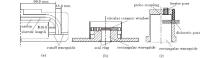
The cavity is composed of three parts, a U-shape cavity, a ceramic window, and a coaxial-to-waveguide converter, as shown in Fig. 2.
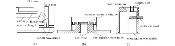 | Fig. 2. The configuration of the cavity. (a) U-shape cavity (half); (b) ceramic window; (c) coaxial-to-waveguide converter. |
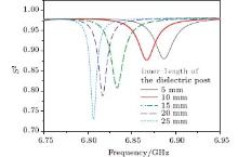
The total electric length of the U-shape cavity is 282.8 mm, basically in accordance with what we calculated theoretically. The microwave-free drift distance between the interaction regions is 199.8 mm accordingly. The aperture's size is 3 mm× 7 mm. A 1.5-mm-thick circular window of alumina ceramics isolates the cavity from the outside. A section of waveguide is added to keep the total resonant frequency of the U-shaped cavity together with the window unchanged. The microwave signal is transmitted by a coaxial line from the microwave source, and a coaxial-to-waveguide converter transfers the signal into the cavity, as in Fig. 2(c). Probe coupling is used here. To increase the coupling degree, the probe should locate at the antinode of the electric field in the waveguide, i.e. multiples of λ g/2 from the shorted plane. It is right next to the shorted plane of the converter in our design. A dielectric post of variable depth on the waveguide's narrow wall serves as the frequency tuning device. Its equivalent circuit is additional shunt and series inductance.[17] The simulated S parameter, the voltage reflection coefficient of the input port, is plotted in Fig. 3. The valleys of the lines correspond to the resonant frequencies and the line widths indicate the quality factors. Simulation shows a tunable range of about 80 MHz is possible with a post 6 mm in diameter and 30 mm in length.
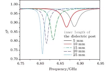 | Fig. 3. Simulated result of the S-parameter of the cavity versus the input frequency, where the inner length of the dielectric post varies from 5 mm to 25 mm. |
It is clearly seen that the resonant frequency varies with the inner length of the dielectric post. This range is enough for mistuning resulting from manufacturing deviation or environmental change. A ferrite post with a diameter of 5 mm and variable depth is for tuning the loaded quality factor. Cavity perturbation theory proves that both QL and ν C of the cavity are shifted when a small ferrite sample is placed in the cavity.[20] According to simulations, in our cavity, the shift in resonant frequency due to the ferrite post is negligible compared with the tuning by the dielectric post. Because the dielectric post acts on the electric field and the ferrite one acts on the magnetic field, they are located at the electric and magnetic antinode respectively to get the largest tuning range. Besides, they should be on the plane of the symmetry of the U-shape cavity to prevent additional end-to-end phase difference. Note that the ferrite post is slightly moved from the optimum position to avoid the input probe.
3.2. Performance test
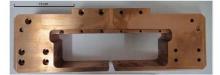
The U-shaped cavity, made of oxygen-free copper, is manufactured in two halves, and screwed together, as shown in Fig. 4.
 | Fig. 4. The fabricated U-shape cavity. |
Care should be taken of the fabrication to minimize distortion and asymmetry. The power response is tested with a Hewlett-Packard 8720D network analyzer, from which one can deduce the resonant frequency and the quality factor. The measured resonant frequency and quality factor are 6.835 GHz and about 500, respectively, when the posts are at default depths. The tunable range of resonant frequency, adjusting the dielectric post, is from 6.82 to 6.88 GHz. The loaded quality value is tunable from 300 to 1000, depending on the inner length of the ferrite post. The resonant frequency and quality factor vary smoothly and almost linearly with the posts' depths. Hence a fine tunning is not difficult monitoring the power response with a network analyzer. The posts should be fastened afterward to avoid mechanical vibration. The tuning range can be enhanced by increasing the total lengths of the posts. The results are quite in accordance with previous theoretical calculations and simulations.
4. Discussion
4.1. Line width of the Ramsey pattern
The drift distance, denoted by L, is 199.75 mm in our design. Assuming the microwave power is at the optimum value, the line width of the central Ramsey pattern is calculated by
 |
where Δ α is a coefficient related to the velocity selection induced by optical pumping and detection.[19]In the laser scheme, where we assume that the light intensity is strong and cycling transition is adopted in detection, Δ α is 3.02. The Ramsey line width is estimated to be 649 Hz, at an oven temperature of 373 K. If lamps are used instead of lasers, where the light spectral intensity is weak, no saturation effect appears during the pumping process. Consequently, slow atoms, which undergo a longer interaction time, are pumped more to the desired state. The line width is narrower under the lamp scheme due to the velocity selective effect.
4.2. Estimation of frequency shifts
The main cause of end-to-end phase difference is asymmetry in the lengths of cavity arms. If a length difference of 0.01 mm exists, which is the tolerance in our manufacturing progress, the relative frequency shift is estimated to be − 3.1× 10− 14, according to Eq. (2). This is quite acceptable for a compact atomic beam clock. However, the actual error introduced in manufacturing and assembling is difficult to estimate. The EPDS can be estimated in further experiments with some methods, e.g., beam reversal.[21]
A cavity quality factor of about 500 is achieved in our design. From Eq. (3), the relative CPS is approximately 1.4× 10− 13 for 1-MHz mistuning, assuming the oven temperature is 373 K and Δ C is 1. Moreover, to minimize this shift, the cavity resonant frequency is supposed to be tuned to 6.835 GHz before operation by adjusting the dielectric post.
5. Conclusion
A method for designing the microwave cavity in our rubidium beam clock is presented, which is also valid for other compact atomic beam frequency standards. The most concerned effects related to the cavity are the end-to-end phase difference and the cavity pulling effect. Hence, requirements on resonant frequency, quality factor and symmetry of the cavity are proposed. The electromagnetic field inside the cavity is simulated by finite element analysis software and dimensions of the cavity are hence determined. The test result coincides with the expected value. Further improvements, which have shown some advantages in previous experiments, such as the ring-type cavity, may be taken into account.
Reference
| 1 |
|
| 2 |
|
| 3 |
|
| 4 |
|
| 5 |
|
| 6 |
|
| 7 |
|
| 8 |
|
| 9 |
|
| 10 |
|
| 11 |
|
| 12 |
|
| 13 |
|
| 14 |
|
| 15 |
|
| 16 |
|
| 17 |
|
| 18 |
|
| 19 |
|
| 20 |
|
| 21 |
|