


Predictive control of a chaotic permanent magnet synchronous generator in a wind turbine system*
Cite this Article
Messadi Manal, Mellit Adel, Kemih Karim, Ghanes Malek. Predictive control of a chaotic permanent magnet synchronous generator in a wind turbine system* . Chinese Physics B, 2014, 24(1): 010502 
Permissions
Predictive control of a chaotic permanent magnet synchronous generator in a wind turbine system*
Corresponding author. E-mail: manal.messadi@ensea.fr
Project supported by the CMEP-TASSILI Project (Grant No. 14MDU920).
Abstract
This paper investigates how to address the chaos problem in a permanent magnet synchronous generator (PMSG) in a wind turbine system. Predictive control approach is proposed to suppress chaotic behavior and make operating stable; the advantage of this method is that it can only be applied to one state of the wind turbine system. The use of the genetic algorithms to estimate the optimal parameter values of the wind turbine leads to maximization of the power generation. Moreover, some simulation results are included to visualize the effectiveness and robustness of the proposed method.
Keyword:
05.45.Gg; 05.45.–a; 02.30.Yy; permanent magnet synchronous generator; chaotic system; genetic algorithm; predictive control
1. Introduction
To protect the environment from the impact of fossil fuel emissions and fossil fuel exhaustion, the amount of wind energy generated has been increasing at a faster pace in the last few years.[1] The wind turbine converts the kinetic energy of wind into mechanical energy, and then into electricity; the rotor blades capture a portion of wind energy, and transfer it to the hub which is fixed on the shaft of the wind turbine. It then transmits the mechanical energy to the electrical generator that converts mechanical energy into electrical energy.[2, 3]
The wind turbine producing electrical energy can use several types of generators, like the double feed induction generator (DFIG), [4] the doubly salient electromagnetic generator (DSEG), [5] the permanent magnet synchronous generator (PMSG), [6] and so on. The choice depends, among other things, on the range of power and location of use.
Thanks to the many advantages of the PMSG like the low manufacturing cost, the high speed, the robustness, compact structure, high efficiency, high torque to inertia ratio, and high power density, the PMSG is interesting for an application generator coupled to a wind turbine and widely known in the industry as a configuration of the most promising wind. In recent years, many researchers have been interested in the control of PMSG.[7, 8]
The PMSG is a typical high nonlinear, multivariable coupled system, and its performance is very sensitive to load disturbances, friction force, and variations of its parameters when the motor shaft is directly coupled with an external load. Some investigations have indicated that the PMSG experiences chaotic behavior when system parameters fall into a certain area.[9– 11] Chaotic behavior in PMSG, which appears mainly as intermittent ripples of torque and low-frequency oscillations of rotational speed of motor, can severely damage the stabilization of the motor and even induce drive system collapse. All these factors make it a challenging problem to control the PMSG to get perfect dynamic performance in the real application. The chaos suppression and control in a PMSG have received much attention in the field of nonlinear control of the electric motor. Until now, various control methods have been developed for chaos suppression and control in a PMSG.[12– 19]
Since the chaos control problem was first considered by Ott et al. in 1990, [20] it has been investigated extensively by many researchers. Recently, many valuable control methods have been developed to control chaotic systems, such as the sliding mode control method, [21] adaptive control method, [22] backstepping method, [23, 24] the passivity feedback control method, [25, 26] constrained generalized predictive control, [27] predictive control, [28– 30] and other methods.[31, 32]
This paper investigates the control of chaos problem in PMSG via predictive control approach. This method is based on combining the delay feedback control method of continuous chaotic systems with the predictive control method of discrete time chaotic systems. To achieve this aim, the genetic algorithms are used to estimate the optimal values of the pitch angle of the adjustable blades turbine and the angular speed, then, a command that will force the generator to follow the optimal trajectory to generate the maximum power will be developed.
2. Wind turbine modeling
The configuration of a PMSG wind turbine is shown in Fig. 1. The variable speed wind turbine, including the mechanical components, the direct drive PMSG, and so on, is a complex electromechanical system. The description of these components will be presented as follows.[33]
 | Fig. 1. Configuration of a PMSG wind turbine. ν : wind; Pw: the power extracted from the wind; MSC: machine-side converter; GSC: grid side converter; β : pitch angle; usabc: stator three-phase voltage; isabc: stator three-phase current; Vdc: dc-link voltage; Pe and Qe: the active and the reactive output power respectively; ilabs: load current. |
2.1. Aerodynamic model of wind turbine
The mechanical power extracted from the wind can be expressed as follows:
 |
where ρ is the air density, R is the turbine radius, Vw is the wind speed, Cp is the power coefficient representing the aerodynamic efficiency of the wind turbine, and Ci is the drag coefficient. In this paper, we assume Ci is constant for simplicity and Cp depends on the tip speed ratio λ and the pitch angle β , given by[16]
 |
with c1 = 0.5109, c2 = 116, c3 = 0.4, c4 = 5, c5 = 21, c6 = 0.0068, where λ represents the ratio between the blades linear speed and the wind speed, which is given by
 |
where w is the rotor angular speed. When λ = λ opt (the optimum value of λ ), Cp has its maximum value Cp max as we can see that in Fig. 2. According to Eqs. (2) and (3), the maximum captured power Popt can be described as
 |
 | Fig. 2. Power coefficient Cp curves of the wind turbine. |
2.2. Model of the PMSG
As is known, the DC motor has a good control performance. Therefore, we try to convert the PMSG into a DC motor from three-phase stationary reference frame to two-phase synchronous reference frame. The process is as follows.
1) Three-phase abc stationary to two-phase α and ψ stationary reference frame. For example, for the three-phase voltages, [34]
 |
2) Two-phase α and ψ stationary to two-phase synchronous rotational reference frame. For example, for the two-phase voltages,
 |
Note, the conversion is similar for other variables. Through a series of conversions similar to Eq. (5) or Eq. (6), we obtain the final mathematical models
 |
where uq and ud are the quadrature and direct axis stator control voltages, iq and id are the quadrature and direct axis stator currents, Lq and Ld are the quadrature and direct axis stator inductance, p is the number of poles pairs, Rs is the stator resistance, ϕ f is the rotor magnet flux linking the stator, Tl is the load torque, J is the rotor moment of inertia, f is the viscous friction coefficient, t′ is the time.
By applying an affine transformation and a time scaling transformation, equation (7) can be transformed into[12]
 |
where

and the time will be redefined to
 |
The vector x is the state vector which takes the forms of x = [w iqid ]T, and the above PMSG model (8) can be transformed into the following normalized PMSG model:
 |
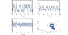
The study found that the PMSG is experiencing chaotic behavior when the operating parameters σ and γ fall into a certain area and the external inputs are set to zero, namely, 
 | Fig. 3. State variable of chaotic PMSG without control and the typical chaotic attractor with system' s parameters σ = 5.45 and γ = 20. (a) w, (b) iq, (c) id, and (d) three-dimensional figure. |
3. Predictive controller approach
In the following paragraph, we develop the predictive control method for controlling the PMSG wind turbine system.
The nonlinear dynamical system of dimension N, is defined by the following equation:[28, 29]
 |
where x(t) is the current state variable of the system, u(t) is the controller, and f(x(t)) is the nonlinear function vector. The aim of the predictive control is to design a controller u(t) such that the trajectory of the system (11) converge to an unstable fixed point xf.
The following theorem establishes that the simple and unique control law u(t) suffices to stabilize the system to an unstable fixed point xf.
Theorem 1[28, 29] The system (11) is globally and asymptotically stable for all initial conditions x(0) = Rn by the predictive feedback control law
 |
where K is a real control parameter.
Proof First, Substituting Eq. (12) into Eq. (11), we obtain
 |
where I ∈ Rn × n is the identity matrix. Near xf, we can use the linear approximation for the uncontrolled system by
 |
Equation (14) can be rewritten as
 |
with
 |
From Eqs. (12), (14)– (16), the controlled system (11) is linearized around xf by
 |
It is important to determine the gain vector K and the neighborhood of the fixed point to adjust the next point so it falls on the fixed one, in order to apply the proposed predictive control strategy. The feedback gain K is determined as follows.
The system (17) is globally and asymptotically stable only if
 |
The neighborhood of the fixed point is given by
 |
The controlled system will be described by
 |
where ζ is a positive small real number.
4. Results and discussion
In this section, numerical simulations are presented to demonstrate and verify the performance of the proposed approach. The command is applied only on the second state, so 
The linear and nonlinear parts of the PMSG system in Eq. (10) are decomposed as follows:
 |
where x(t) = (x1, x2, x3)T, 
In order to control the PMSG system to its equilibrium point (0, 0, 0)T, the control input u(t) is defined by
 |
The feedback gain K is determined as |A + K(A – I)|. < I. This implies that: – 3.1 < K < − 1.08.
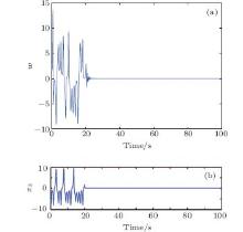
 | Fig. 4. Angular speed of PMSG controlled to the equilibrium at t = 20 s with a predictive controller (a) and with a fuzzy guaranteed cost controller[35] (b). In panel (b), x3 means ω . |
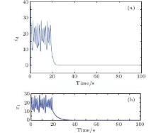
Figures 4– 6 represent respectively, the angular speed w and the currents iq and id controlled to the equilibrium point at t = 20 s. To show the effectiveness of the approach reported in this paper, a comparison of results obtained with a fuzzy guaranteed cost controller[35] is presented. Comparing to the fuzzy guaranteed cost controller, the predictive controller provides faster convergence to the equilibrium point.
 | Fig. 5. q-axes current of PMSG controlled to the equilibrium point at t = 20 s with a predictive controller (a) and a fuzzy guaranteed cost controller[35] (b). In panel (b), x2 means iq. |
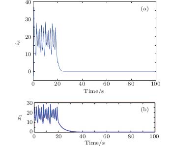 | Fig. 6. d-axes current of PMSG controlled to the equilibrium point at t = 20 s with a predictive controller (a) and a fuzzy guaranteed cost controller[35] (b). In panel (b), x1 means id. |
In order to optimise the wind turbine equipped with a chaotic PMSG, the GAs[36, 37] are used to estimate the optimum values of the pitch angle β opt and wopt that will maximize the value of the power coefficient CPmax, according to the following steps.
Step 1 Initialization At the beginning of the optimization procedure, a population of size Nsize of randomly generated (β and λ ) is created and called P(0). The fitness of each individual is evaluated based on a given model of the process. Note that this model can change during process operation if a recursive identification algorithm is used in the procedure.
Step 2 Optimization Time t, starting from t = 1, and given the population P(t – 1), compute successive generations of same size using the GA. New populations are computed until the maximum number of generations has been reached or until the fitness of the best individual does not improve any longer. At the end of this step, the best individual is denoted (β * and λ *) and the population to which it belongs is denoted P(t).
Step 3 Control computation Apply the constraint reduction method to current control in order to satisfy process constraints.
Step 4 Calculate the control value U(t) according to the algorithm's horizon β * and λ *, and apply this control value to the system.
Step 5 Let t = t + 1 and go back to Step 2.
The proposed genetic-based control algorithm for the wind turbine is tested for a random variation of wind speed as shown in Fig. 7.
 | Fig. 7. Wind speed profile. |
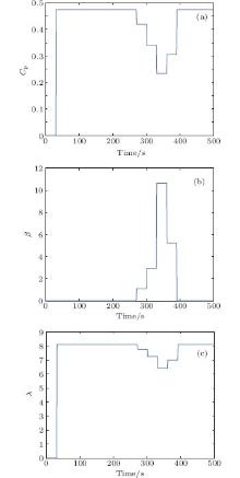
Figures 8(a)– 8(c) represent respectively the optimal values of the power coefficient, the pitch angle and the tip speed ratio. When the values of wind are lower then 12 m/s, the power coefficient Cp takes a maximum value and the pitch angle β is null, and if the wind speed is larger than 12 m/s, the pitch angle β is open to adjust the speed of the mechanical torque, so its value increases and the value of the power coefficient Cp decreases.
Figures 9(a)– 9(b) represent successively the optimal values of the angular speed and the maximum values of the power captured by the wind; these optimal values are maximum when the wind speed exceeds 12 m/s.
 | Fig. 8. The optimal value of the power coefficient (a), the optimal pitch angle (b), and the optimal tip speed ratio (c) obtained by using the GA. |
In this part, the predictive controller is applied into PMSG based wind power system for tracking wopt, for that, an external input η is introduced into Eq. (12) which becomes
 |
We want to steer the state of the PMSG system to a set point 
 |
Substituting Eq. (12) into Eq. (10) and letting 
 | Fig. 9. The optimal angular speed (a) and the maximum captured power (b) obtained by using the GA. |
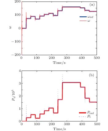 | Fig. 10. (a) Angular speed controlled of the PMSG and the angular speed reference. (b) Captured power controlled of the PMSG and the captured power reference. |
From Figs. 10(a) and 10(b), the PMSG properly tracks the imposed reference and the wind turbine generates the desired power. Figures 11(a) and 11(b) show the controlled currents iq and id.
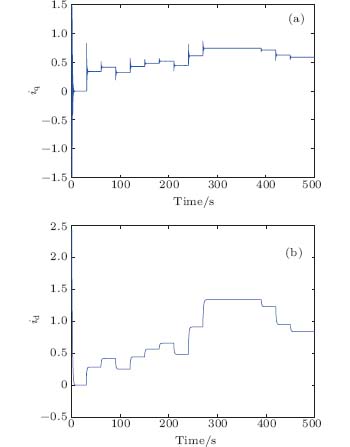 | Fig. 11. Controlled currents iq (a) and id (b). |
5. Conclusion
In this paper, the control of a chaotic PMSG wind turbine system has been considered via predictive control and genetic algorithms. The genetic algorithms are used to estimate the optimal values of the pitch angle of the adjustable blades turbine and the angular speed, then, the predictive control is used to track the optimal angular speed in order to generate the maximum power. Simulation results have been provided to demonstrate the effectiveness and the performance of the proposed approach.
Reference
| 1 |
|
| 2 |
|
| 3 |
|
| 4 |
|
| 5 |
|
| 6 |
|
| 7 |
|
| 8 |
|
| 9 |
|
| 10 |
|
| 11 |
|
| 12 |
|
| 13 |
|
| 14 |
|
| 15 |
|
| 16 |
|
| 17 |
|
| 18 |
|
| 19 |
|
| 20 |
|
| 21 |
|
| 22 |
|
| 23 |
|
| 24 |
|
| 25 |
|
| 26 |
|
| 27 |
|
| 28 |
|
| 29 |
|
| 30 |
|
| 31 |
|
| 32 |
|
| 33 |
|
| 34 |
|
| 35 |
|
| 36 |
|
| 37 |
|